General Co-Chairs
Shigeru Obayashi, Tohoku University
Integration 2012 Integration 2012
5th Symposium on Integrating CFD and Experiments in Aerodynamics
g y , y
Shigeya Watanabe, Japan Aerospace Exploration Agency (JAXA)
International Scientific Panel
Ken Badcock, University of Liverpool Russell Cummings, United States Air
Force Academy
Kevin Knowles, Cranfield University Shigeru Obayashi, Tohoku University Philippe Planquart, von Karman
Institute
Patrick Rambaud, von Karman Institute Alistair Saddington, Cranfield
University Shigeya Watanabe, JAXA
Local Scientific Committee
Keisuke Asai, Tohoku University Takayuki Ito, Ochanomizu University Takeshi Ito, JAXA
Masahiro Kanazaki, Tokyo Metropolitan University
©JAXA
p y
Hiromitsu Kawazoe, Tottori University Yuichi Matsuo, JAXA
Shigeru Obayashi, Tohoku University Akihiro Sasoh, Nagoya University Keisuke Sawada, Tohoku University Kojiro Suzuki, University of Tokyo Makoto Tsubokura, Hokkaido
University Shigeya Watanabe, JAXA Kazuomi Yamamoto, JAXA Kenji Yoshida, JAXA
Local Organizing Committee
Hideaki Aiso, Chair, JAXA Kentaro Imagawa, JAXA Shigeru Kuchi-Ishi, JAXA Hiroyuki Kato, JAXA Keiichi Murakami, JAXA Toshiyuki Suzuki, JAXA
October 3
October 3--5, 2012 5, 2012 JAXA
JAXA Chofu Chofu Aerospace Center Aerospace Center Tokyo, JAPAN
Tokyo, JAPAN
http://integration2012.jaxa.jp
http://integration2012.jaxa.jp
Wednesday, Octorber 3, 2012
8:30-16:00 Registration 9:30 Opening Ceremony
9:45 Invited Lecture 1 chaired by Kenji Yoshida (JAXA, Japan) 1
IL1, EFD/CFD for MRJ Development
Ichiro Maeda, Keita Hatanaka (Mitsubishi Aircraft Co., Japan)
10:30 1-1, DAHWIN - Digital/Analog-Hybrid Wind Tunnel 13
Shigeya Watanabe, Shigeru Kuchi-Ishi, Keiichi Murakami, Atsushi Hashimoto, Hiroyuki Kato, Tatsuya Yamashita, Kanako Yasue, Kentaro Imagawa (JAXA, Japan), Hideji Saiki, Jyun Ogino (Ryoyu Systems Co., Ltd., Japan)
11:00 1-2, Development of Digital Wind Tunnel as a Subsystem of JAXA Digital/Analog Hybrid Wind Tunnel 29 Keiichi Murakami, Atsushi Hashimoto (JAXA, Japan), Manabu Hishida (Ryoyu Systems Co., Ltd., Japan), Paulus R. Lahur (Research Center of Computational Mechanics, Inc., Japan), Akira Kunieda (CEC Ltd., Japan), Shigeya Watanabe (JAXA, Japan)
11:30 Poster Presentations chaired by Kenji Yoshida (JAXA, Japan) 12:00 Lunch & Poster Session
14:00 Invited Lecture 2 chaired by Shigeru Obayashi (Tohoku University, Japan) 37
IL2, Overview of Activities in Stochastic Data Assimilation for Applications in Aerodynamics Richard Dwight (Delft University of Technology, Netherlands)
14:45 2-1, Using Proper Orthogonal Decomposition Methods for Comparing CFD Results to Experimental
Measurements 55
Thomas Andrianne, Amandine Guissart, Greg Dimitriadis, Vincent Terrapon (University of Liege, Belgium) 15:15 Coffee Break
15:45 3-1, Experience in the application of numerical methods to TsAGI's wind-tunnel testing techniques 67 S. L. Chernyshev, V. Ya. Neyland, S. M. Bosnyakov, S. A. Glazkov, A. R. Gorbushin, I. A. Kursakov, V. V. Vlasenko (TsAGI,
Russian Federation)
16:15 3-2, A Methodology to Derive Wind Tunnel Wall Corrections from RANS Simulations 83
Jean-Luc Hantrais-Gervois, Jean-François Piat (ONERA, France)
16:45 3-3, Wall Interference Analysis by Whole Wind Tunnel CFD 103
Atsushi Hashimoto, Masataka Kohzai (JAXA, Japan)
17:15 3-4, Prediction of the Aerodynamic Effect of Model Deformation during Transonic Wind Tunnel Tests 115 Sylvain Mouton, Marianne Lyonnet, Yves Le Sant (ONERA, France)
17:45
18:00-20:00Reception (Exhibition Hall, JAXA CAC)
Integration 2012
5th Symposium on Integrating CFD and Experiments in Aerodynamics
3rd to 5th October, 2012
JAXA Chofu Aerospace Center, Tokyo, JAPAN
Technical Session Program
Session 1: Digital/Analog-Hybrid Wind Tunnel (DAHWIN) chaired by Kenji Yoshida (JAXA, Japan)
Session 2: Data Assimilation-1 chaired by Shigeru Obayashi (Tohoku University, Japan)
Session 3: Wind Tunnel Application chaired by Shigeya Watanabe (JAXA, Japan)
Thursday, Octorber 4, 2012
9:00-16:00 Registration
9:30 Invited Lecture 3 chaired by Shigeru Kuchi-Ishi (JAXA, Japan) 131
IL3, InfoSymbiotics - The power of Dynamic Data Driven Applications Systems (DDDAS) Frederica Darema (Air Force Office of Scientific Research, United States of America)
10:15 Coffee Break
10:45 4-1, Numerical Noise Prediction of a generic Flap Configuration 157
Lilla Kapa-Koloszar, Patrick Rambaud, Philippe Planquart, Christophe Schram(VKI, Belgium)
11:15 4-2, Computational Efforts in Designing Experiment for High-Lift Aeroacoustics 167
Mitsuhiro Murayama, Yuzuru Yokokawa, Kazuomi Yamamoto, Kazuhisa Amemiya (JAXA, Japan), Kentaro Tanaka, Tohru Hirai (Ryoyu Systems. Co. Ltd., Japan),
11:45 4-3, Integrating CFD, CAA, and Experiments towards Benchmark Datasets for Airframe Noise Problems 183 Meelan Choudhari (NASA, United States of America), Kazuomi Yamamoto (JAXA, Japan)
12:15 Lunch
13:15 Invited Lecture 4 chaired by Tomoyuki Higuchi (Institute of Statistical Mathematics, Japan) 191 IL4, Integration of CFD and EFD for Analysis of Complex Real Flows
Toshiyuki Hayase (Tohoku University, Japan)
14:00 5-1, Sensitivity Analysis of Unsteady Flow Fields and Numerical Experiments for Optimal Measurement 209 Takashi Misaka (DLR, Germany), Shigeru Obayashi (Tohoku University, Japan)
14:30 5-2, Application of the Measurement Integrated Simulation Method to Compressible Fluid Problems 217 Kentaro Imagawa, Kanako Yasue, Shigeru Kuchi-Ishi (JAXA, Japan)
15:00 5-3, Toward the Development of Measurement Integrated Simulation 229
Hiroshi Kato, Shigeru Obayashi (Tohoku University, Japan) 15:30 Coffee Break
16:00 6-1, A Variable Fidelity Response Surface Approach towards Integration of CFD and EFD 243 Wataru Yamazaki (Nagaoka University of Technology, Japan), Shigeru Kuchi-Ishi (JAXA, Japan)
16:30 6-2, Requirements for Computer Generated Aerodynamic Models for Aircraft Stability and Control Analysis A. McCracken, U. Akram, A. Da Ronch, K.J. BadcockKenneth Badcock (University of Liverpool, United Kingdom)
17:00 6-3, A Study on the Performance of Fluidic Thrust Vector Control Utilizing Supersonic Coanda Effects 253 MyungJun Song, SangHun Yoon (Korea Aerospace University, Republic of Korea), HongBeen Chang (Agency for Defense
Development, Republic of Korea), YongHo Cho (Micro Friend, Inc, Republic of Korea), Yeol Lee (Korea Aerospace University, Republic of Korea)
17:30 6-4, Measurements of Counter Flow Region in Averaged Wake-Velocity-Field of a Small Straight-Bladed
Vertical Axis Wind Turbine 263
Yutaka Hara, Takahiro Suzuki, Hirofumi Kamon (Tottori University, Japan)
18:00
19:00-21:30Banquet (KICHIJOJI PARK CAFE, Kichijoji Tokyu INN 1F)
Session 4: Aeroacoustics chaired by Yuichi Matsuo (JAXA, Japan)
Session 5: Data Assimilation-2 chaired by Tomoyuki Higuchi (Institute of Statistical Mathematics, Japan)
Session 6: Modeling/Flow Control/Wind Turbine chaired by Hiromitsu Kawazoe (Tottori University, Japan)
Friday, Octorber 5, 2012
8:30-10:00 Registration
9:00 Invited Lecture 5 chaired by Kojiro Suzuki (The University of Tokyo, Japan) 271 IL5, CFD for Aerodynamic Flight Performance Prediction: From Irrational Exuberance to Sobering Reality
Pradeep Raj (Virginia Tech, United States of America) 9:45 Coffee Break
10:15 7-1, A Combined Study on Shock Diffraction 279
Mark Kenneth Quinn, Konstantinos Kontis (University of Manchester, United Kingdom)
10:45 7-2, Wind Tunnel and CFD Studies on Production of Prebiotic Materials in Hypersonic Flow around
Extraterrestrial Entry Object 295
Kojiro Suzuki, Yasumasa Watanabe (The University of Tokyo, Japan)
11:15 7-3, Experimental and Numerical Study on Shock Layer Radiation for Planetary Entry Flights 307 Gouji Yamada, Shota Ago, Yuto Kubo, Takashi Matsuno, Hiromitsu Kawazoe (Tottori University, Japan)
11:45 7-4, Numerical Study on Anomalous Heating over Apollo CM Test Model in Free-Piston Shock Tunnel HIEST 317 Tomoaki Ishihara, Yousuke Ogino, Naofumi Ohnishi, Keisuke Sawada (Tohoku University, Japan), Hideyuki Tanno (JAXA,
Japan)
12:15-14:30Lunch (Jindaiji, Suijin-en) 14:30-16:45Technical Tours (JAXA CAC) 16:45-17:00Closing Ceremony
P1, Visualization of Unsteady Behavior of Shock Waves around Supersonic Intake installed in Shock Tunnel 327 Naruaki Tanaka, Toshiharu Mizukaki (Tokai University, Japan)
P2, Experimental investigation of initial shear-layer effect on the pressure oscillation in supersonic cavity 335 Takaya Ozaki, Shinji Maruyama (Kyushu University, Japan), Hatsuki Kakuno (Nippon Steel Engineering Co., Ltd., Japan), Taro Handa (Kyushu University, Japan)
P3, Aerodynamic Characteristics of a Delta Wing with Arc Camber for Mars Exploration 343 Takao Unoguchi, Shogo Aoyama, Hiroshi Suemura, Gouji Yamada, Takashi Matsuno (Tottori University, Japan), Shigeru
Obayashi (Tohoku University, Japan), Hiromitsu Kawazoe (Tottori University, Japan)
P4, CFD Calculation of Airfoil Characteristics for Performance Prediction of Vertical Axis Wind Turbine 353 Naoko Inoue, Kana Tanaka, Yutaka Hara, Takahiro Sumi (Tottori University, Japan)
P5, Multi-objective Optimization of Airfoil of Mars Exploration Aircraft using Evolutionary Algorithm 361 Gaku Sasaki (Kyusyu Institute of Technology, Japan), Tomoaki Tatsukawa, Taku Nonomura (JAXA, Japan), Koichi Yonemoto
(Kyusyu Institute of Technology, Japan), Akira Oyama (JAXA, Japan), Takaaki Matsumoto, Tomohiro Narumi (Kyusyu Institute of Technology, Japan)
P6, Bow-shock instability around an Edged Ballistic Object in a Low-Gamma Gas 367 Yosuke Sato (Tohoku University, Japan), Kanako Yasue (JAXA, Japan), Takamasa Kikuchi, Kiyonobu Ohtani, Naofumi Ohnishi (Tohoku University, Japan)
P7, A Study on Pressure Variation of a Rotor Blade Tip using PSP 375
Kidong Kim (University of Science and Technology, Republic of Korea), Kijung Kwon (KARI, Republic of Korea) P8, Assessment of some experimental and processing factors for background oriented schlieren
measurements 385
Ardian B. Gojani, Shigeru Obayashi (Tohoku University, Japan)
P9, Dynamic Wind-Tunnel Testing of a Delta Wing Using a Multi-Degree-of-Freedom Robotic Manipulator 397 Tatsuya Hara, Daiju Numata, Keisuke Asai, Takahumi Ito, Xin Jiang (Tohoku University, Japan)
P10, Integration between Measurements and Particle Simulations for Hypersonic Rarefied Flows 407 Takashi Ozawa, Toshiyuki Suzuki, Kazuhisa Fujita (JAXA, Japan)
P11, Experimental Data Reconstruction Using CFD Results Based on Proper Orthogonal Decomposition 417 Kanako Yasue, Shigeru Kuchi-Ishi, Shigeya Watanabe (JAXA, Japan)
P12, Drag and Lift Estimation from 3-D Velocity Field Data Measured by Multi-Plane Stereo PIV 425 Hiroyuki Kato (JAXA, Japan), Kisa Matsushima (University of Toyama, Japan), Makoto Ueno, Shunsuke Koike, Shigeya
Watanabe (JAXA, Japan)
Session 7: Supersonic/Hypersonic Flow chaired by Keisuke Sawada (Tohoku University, Japan)
Poster Session:
5th Symposium on Integrating CFD and Experiments in Aerodynamics (Integration 2012) 1
MITSUBISHI AIRCRAFT CORP. PROPRIETARY NA231103 NC 2/
1. Introduction of MRJ
2. EFD/CFD for MRJ Development 3. Future prospect on EFD and CFD
MITSUBISHI AIRCRAFT CORP. PROPRIETARY NA231103 NC 1/
Mitsubishi Aircraft Corporation Ichiro Maeda
2012/10/03
Integration 2012
EFD/CFD for MRJ Development 㻌
MITSUBISHI AIRCRAFT CORP. PROPRIETARY NA231103 NC 4/
Vision and Key Features
Key Features
Airlines
Most Efficient Aircraft
■Game-Changing Engine
■Advanced Aerodynamics
■Human-Centered Flight Deck
■Composite Structure
Environment
Lowest Fuel Burn, Noise, Emissions
■Game-Changing Engine
■Advanced Aerodynamics
Passengers
Most Comfortable Cabin
■Passenger-Oriented Cabin
■New Slim Seat
【 Vision 】
Apply advanced mainline jet technology to regional jet and create the standard for next-generation regional jet.
Offer unprecedented values for environment, passengers, and airlines.
MITSUBISHI AIRCRAFT CORP. PROPRIETARY NA231103 NC 3/
Commercial Jet Market
Regional Jet Narrow
Body Wide Body
㻝㻜㻜 㻞㻜㻜 㻟㻜㻜 㻠㻜㻜 㻡㻜㻜
Seats
㻜
A350 B767
B747 B777 B787
A380 A340
A330
B737/MAX A320/neo
CSeries C919
MS21
CRJ ARJ21
SSJ100 E-Jet
MRJ
More than 28,000 airplanes to be delivered in the next 20 years
Fierce competition with five regional jet makers
5th Symposium on Integrating CFD and Experiments in Aerodynamics (Integration 2012) 3
MITSUBISHI AIRCRAFT CORP. PROPRIETARY NA231103 NC 6/
General Arrangement - MRJ90
29.2 m / 95.9 ft
5.3 m / 17.5 ft
35.8 m / 117.4 ft
14.0 m / 45.9 ft
10.5 m / 34.4 ft 11.0 m / 36.2 ft
Designed for fuel efficiency without compromising cabin comfort
High aspect ratio wing
with winglets, small diameter fuselage, and innovative GTF engine
GTF: Geared Turbo Fan
MITSUBISHI AIRCRAFT CORP. PROPRIETARY NA231103 NC 5/
MRJ Family
MRJ 100X (Plan) MRJ 90
MRJ 70
78 seats 92 seats 100 seats
Three models to cover global market needs
High commonality for airline economics
pilot type rating, engines, maintenance program and spare parts
MITSUBISHI AIRCRAFT CORP. PROPRIETARY NA231103 NC 8/
Passengers – Most Comfortable Cabin
Mainline jet comfort
Same seat width as 787 with 8 abreast
Ample head & foot clearance at the seat
Large overhead bin
MRJ 18.5 in
787 (8abreast) 18.5 in 787 (9abreast) 17.2 in EMB170/190 18.25 in
CRJ 17.3 in
0.05 m / 2 in
2.03 m / 80 in
0.47 m / 18.5 in
0.46 m / 18 in Maximum size
roller bag† 25 x 45 x 56 cm 9.8 x 17.7 x 22.0 in
1.88 m / 74 in (US Male 97.5%ile)
2.76 m / 108.5 in
† IATA-recommended maximum size bag MITSUBISHI AIRCRAFT CORP. PROPRIETARY NA231103 NC 7/
Optimum range capability for regional operations
Well accepted by US, Europe, Asia and other global markets
Range Capability
NAGOYA
Tokyo Shanghai
Taipei Seoul Beijing Harbin
Guam Okinawa
Sapporo
Manila
PARIS
Algiers
Ankara Bucharest
Kiev Warsaw
Moscow Oslo Reykjavik
Athens London
Lisbon Rabat
DENVER
Los Angeles
Mexico City Houston San Francisco
Edmonton
Seattle Ottawa
New York
Miami Washington
From Nagoya
From Paris From Denver
MRJ90 MRJ70
Range Circle
with Wind
5th Symposium on Integrating CFD and Experiments in Aerodynamics (Integration 2012) 5
MITSUBISHI AIRCRAFT CORP. PROPRIETARY NA231103 NC 10/
Environment – Lowest Emission
*Mitsubishi Aircraft estimation, 500nm Trip, 2,200 cycle/year, Fuel price 3$/USG
CO2 emission
(%) Current
RJ
0 100
MRJ90
More than 20%
CO
2Reduced by More than 4,000 t./ year / a/c
8060 40 20
=
•Advanced aerodynamics and GTF engine for low fuel burn
•Significantly Lower Fuel Burn & CO
2Emissions
MITSUBISHI AIRCRAFT CORP. PROPRIETARY NA231103 NC 9/
Environment – Lowest Noise
Advanced aerodynamics and GTF engine for low noise
MRJ90 noise area reduced by 40%
* Mitsubishi Aircraft Estimation at Schiphol Airport (AMS)
MRJ90 Current RJ
㻌 㻌 㻌 㻌 㻌 㻌 85 dBA 㻌 㻌 㻌 㻌 㻌 㻌 80 dBA 㻌 㻌 㻌 㻌 㻌 㻌 75 dBA 㻌 㻌 㻌 㻌 㻌 㻌 70 dBA 㻌 㻌 㻌 㻌 㻌 㻌 Flight Path 㻌 㻌 㻌 㻌 㻌 㻌 85 dBA
㻌 㻌 㻌 㻌 㻌 㻌 80 dBA 㻌 㻌 㻌 㻌 㻌 㻌 75 dBA 㻌 㻌 㻌 㻌 㻌 㻌 70 dBA 㻌 㻌 㻌 㻌 㻌 㻌 Flight Path
MITSUBISHI AIRCRAFT CORP. PROPRIETARY NA231103 NC 12/
Aerodynamic characteristics will be validated by flight test.
Aerodynamic design : designed by CFD and evaluated by EFD
Aerodynamic data : estimated by EFD interpolated or corrected with CFD Noise prediction : investigated/estimated/evaluated by EFD and CFD EFD application
・ Wind tunnel tests (examples)
・ Flow visualizations by advanced optical measurements
・ Noise source survey at low speed wind tunnel CFD application
・ CFD technology
・ Simulation for all configurations
・ Aerodynamic design based on MDO
・ Equipment installation design for ADS and ECS
・ Investigation for noise generation and propagation
EFD/CFD for MRJ Development : outline 㻌
MITSUBISHI AIRCRAFT CORP. PROPRIETARY NA231103 NC 11/
Milestones and Events
Iron Bird Dec./2011
First Rivetting April/2011 Metal Cut Ceremony
Sep./2010
Paris Airshow June/2011
Last Bolt Ceremony
Mar./2011 First Engine to Test
May/2011
Farnborough Airshow July/2012
5th Symposium on Integrating CFD and Experiments in Aerodynamics (Integration 2012) 7
MITSUBISHI AIRCRAFT CORP. PROPRIETARY NA231103 NC 14/
㻌
Advanced optical measurement technologies ( JAXA/MHI collaborative work )
・ PSP ( Pressure Sensitive Paint ) : aerodynamic load estimation.
・ PIV ( Particle Image Velocimetry ) : evaluation of chine design.
Velocity distribution around the wing-pylon junction (PIV)@High AoA of HLD cfg.
CFD PSP
Wing Pressure Distribution at Cruise condition
δ
sp= 0deg δ
sp= 20deg δ
sp= 60deg
with Chine w/o ChineEFD for MRJ Development : Flow Visualization 㻌
MITSUBISHI AIRCRAFT CORP. PROPRIETARY NA231103 NC 13/
EFD for MRJ Development : Wind Tunnel Tests 㻌
High speed wind tunnel test@ JAXA 2m×2m TWT
JAXA/MHI collaborative work
Ground effect test@ MHI 2m LWT
20% half span model@ JAXA 6.5m×5.5m LWT JAXA/MHI collaborative work
10% full span model@ JAXA 6.5m×5.5m LWT JAXA/MHI collaborative work 2.9m
2.9m 1m
MITSUBISHI AIRCRAFT CORP. PROPRIETARY NA231103 NC 16/
CFD for MRJ Development : CFD Technology
Apply CFD technology developed by collaborative work with Tohoku Univ. and JAXA
⇒㻌 Over 100,000 CPU hours calculation!
㻌
CFD Tool for Complex Geometry (C
ollaborative work with Tohoku Univ. ) - Unstructured Mesh : TAS (Tohoku Univ. Aerodynamics Simulation)㻌 㻌 - Cartesian Mesh : BCM (Building-Cube Method)
㻌
Parallel Computing with Supercomputers (JSS, Cyber Science Center)
Collaborative work with JAXA and Tohoku Univ.- Standard Steady Calculations : Aerodynamic Design etc.
- Large Scale Unsteady Calculations : Noise and Flutter Analysis
TAS BCM
MITSUBISHI AIRCRAFT CORP. PROPRIETARY NA231103 NC 15/
JAXA 6.5m x 5.5m LWT
スラット騒音の可視化
Noise visualization for HLD cfg.
Slat noise
Gear noise Microphone array
㻌
Noise source survey (JAXA/MHI collaborative work)
・ Evaluate aerodynamic properties and noise level simultaneously.
・ Understand where the noise comes from.
EFD for MRJ Development : Noise prediction 㻌
5th Symposium on Integrating CFD and Experiments in Aerodynamics (Integration 2012) 9
MITSUBISHI AIRCRAFT CORP. PROPRIETARY NA231103 NC 18/
CFD for MRJ Development : Aerodynamic Design
Wing CFD mesh
Engine CFD mesh Wing FEM model
Engine FEM model Wing CFD mesh
Engine CFD mesh Wing FEM model
Engine FEM model
MDO ( Multidisciplinary Design Optimization ) developed by Tohoku Univ.
Apply to aerodynamic designs of wing/engine configuration and winglet
Optimize aerodynamics (drag, lift ) and structure (size, weight) simultaneously under constraints from design requirements.
Initial
Optimized
Design of Wing/Engine Configuration Winglet㻌 Design CFD : Aerodynamic characteristics and aerodynamic load
FEM : Internal forces and displacement of structure
MITSUBISHI AIRCRAFT CORP. PROPRIETARY NA231103 NC 17/
CFD for MRJ Development : All Configurations
Data productivity criteria for practical aircraft design : more than 1 case/day.
Simulate all configurations of aircraft operation in a practical time.
Apply to thrust reverser design to improve design efficiency and reduce risks before flight test.
Take-off/Landing Configurations 10 million mesh points, 3 cases/day Cruise Configuration
7.5 million mesh points 10 cases/day
Braking with Thrust Reverser 15 million mesh points, 1 case/day Take-off
Cruise
Landing Braking Spoilers
Ground
MITSUBISHI AIRCRAFT CORP. PROPRIETARY NA231103 NC 20/
1
• CFD(BCM)を用いて物体まわりの 流体計算を行う
•物体の表面圧力変動p’(y,t)を得る
1
1
• CFD(BCM)を用いて物体まわりの 流体計算を行う
•物体の表面圧力変動p’(y,t)を得る
• CFD(BCM)を用いて物体まわりの 流体計算を行う
•物体の表面圧力変動p’(y,t)を得る
3
•推定音圧をFFT処理し,Sound Pressure Level (SPL)を求める
3
•推定音圧をFFT処理し,Sound Pressure Level (SPL)を求める
3
3
•推定音圧をFFT処理し,Sound Pressure Level (SPL)を求める
•推定音圧をFFT処理し,Sound Pressure Level (SPL)を求める
p・・変動音圧の実効値
20 2
log
1010 p
SPL p
e2
• p’(y,t)よりCurleの式を用いて遠方 場における音圧を推定する
y t r c
dS pt n x
Pa c i2
i 00
4 , 1
x2
• p’(y,t)よりCurleの式を用いて遠方 場における音圧を推定する
2
• p’(y,t)よりCurleの式を用いて遠方 場における音圧を推定する
2
2
• p’(y,t)よりCurleの式を用いて遠方 場における音圧を推定する
• p’(y,t)よりCurleの式を用いて遠方 場における音圧を推定する
y t r c
dS pt n x
Pa c i2
i 00
4 , 1
xCoarse Fine
Noise prediction and Low-noise design by collaborative work with JAXA and Tohoku Univ.
Investigation of noise source and prediction of airframe noise with acoustic analysis for community noise
Prediction of engine noise propagation into cabin for passenger noise
LEE* for Fan Noise Propagation to Cabin
(Courtesy of JAXA) LES* for Slat Noise
(Courtesy of JAXA)
*LES:Large Eddy Simulation *LEE:Linearized Euler Equation
BCM*/LES for Landing Gear Noise
(Collaboration with Tohoku Univ.)
*BCM:Building-Cube Method
CFD for MRJ Development : Noise prediction 㻌
MITSUBISHI AIRCRAFT CORP. PROPRIETARY NA231103 NC 19/
Toward CFD for “Actual aircraft ”, instead of aero “Aircraft model”
• Protuberance drag, conventionally estimated with hand-book method.
• Location of ADS, conventionally defined at WT and FT.
• Performance of air inlet/outlet for ECS, APU, ventilation etc.
Evaluation of Small-size Equipments
Performance Evaluation of Inlet/Outlet of ECS* ram air flow
CD =0.0300 㻌 㻌 㻌 :Total Drag of Airplane (about 1/10 of Car ) ΔCD =10-4(1count)㻌 :Low-Drag Design
ΔCD =10-6 㻌 㻌 㻌 :Drag of a Sensor
Miscellaneous drag = 5% of CD!!!
ADS*
CFD for MRJ Development : High fidelity simulation 㻌
*ADS:Air Data Sensor
*ECS:Environment Control System
This document is provided by JAXA.
5th Symposium on Integrating CFD and Experiments in Aerodynamics (Integration 2012) 11
MITSUBISHI AIRCRAFT CORP. PROPRIETARY NA231103 NC 22/
http://www.mrj-japan.com/
Mitsubishi Regional Jet, a new concept from Japan for the skies of the world.
MITSUBISHI AIRCRAFT CORP. PROPRIETARY NA231103 NC 21/
Issues to be improved : EFD
・ Lead time for test model preparation : design/manufacturing ・ Data productivity : per day/per test run
・ Accuracy of measurement : drag
・ Compensation for the effects due to flow condition differences : Re/facility etc.
CFD
・ Lead time for calculation model preparation : geometry/grid generation ・ Data productivity : hardware, algorithm
Further application : EFD
・ Extension to flight test : optical measurement/noise source survey ・ Unsteady measurement : PSP for buffet
CFD
・ Integration of multi-flow field : internal/external flow of equipment ・ Unsteady simulation : dynamic stability/noise prediction
Future prospect on EFD and CFD 㻌
5th Symposium on Integrating CFD and Experiments in Aerodynamics (Integration 2012) 3-5 October 2012
JAXA Chofu Aerospace Center, Tokyo, Japan
1
DAHWIN - Digital/Analog-Hybrid Wind Tunnel
Shigeya Watanabe Shigeru Kuchi-ishi Keiichi Murakami Atsushi Hashimoto Hiroyuki Kato Tatsuya Yamashita Kanako Yasue Kentaro Imagawa
Japan Aerospace Exploration Agency (JAXA) Chofu, Tokyo 182-8522
Japan
[email protected] Hideji Saiki
Jyun Ogino
Ryoyu Systems Co., Ltd.
Nagoya, Aichi 464-0075 Japan
Abstract
The development of ‘Digital/Analog-Hybrid WINd tunnel (DAHWIN),’ which is an innovative system integrating CFD (Computational Fluid Dynamics) with EFD (Experimental Fluid Dynamics), is presented. The aim of the system is to improve efficiency, accuracy, and reliability of aerodynamic characteristics evaluation in aerospace vehicle developments through mutual support between EFD and CFD. DAHWIN is constructed based on two large facilities, JAXA 2m x 2m Transonic Wind Tunnel for EFD and JAXA Supercomputer System for CFD. The function of this system consists of optimization of test planning, an accurate correction of the wind tunnel wall and support interaction effects, the most probable aerodynamic characteristics estimation based on both EFD and CFD data, and so forth. Key technical challenges in the system development, such as an automatic grid generator, high-speed CFD solver, and a high-speed data processing technique for image measurement data, are addressed. Some preliminary applications of DAHWIN to practical wind tunnel tests showed the usefulness and reliability of DAHWIN.
Key words: EFD, CFD, Wind Tunnel, Database, Data Fusion
Introduction
In order to evaluate aerodynamic characteristics of aircraft and aerospace vehicles, experimental techniques using wind tunnels (experimental fluid dynamics: EFD) were mainly employed as well as theoretical methods till 1970’s. However, since then, computational fluid dynamics (CFD) has been gaining its importance in the aerodynamic prediction with significant advances of CFD techniques and processing speed of computers. At present, it could be addressed that the importance of CFD in aerodynamic design is comparable to that of EFD.
5th Symposium on Integrating CFD and Experiments in Aerodynamics (Integration 2012) 3-5 October 2012
JAXA Chofu Aerospace Center, Tokyo, Japan
2
On the other hand, still now, EFD and CFD are usually conducted separately by different groups of experts with relatively weak interaction and collaboration. This situation in the aerodynamic characteristics prediction indicates that as the next step, synergy of EFD/CFD integration is expected to improve the prediction techniques further.
Researches aiming at such real integration of the two techniques do not seem to be matured so far while some trials have been reported with certain degree of success at laboratory condition [1-2]. In particular, practical applications of EFD/CFD integration in industrial aerospace development are very few except the system called ViDI (Virtual Diagnostics Interface System) developed by NASA Langley Research Center [3]. Although the ViDI system was originally developed to aid pretest design of optical fluid diagnostic techniques such as Pressure-Sensitive Paint (PSP), it has the capability of real time comparisons of experimental results with pretest CFD calculations using 3-D graphic feature called Live View 3D. However, the comparisons are done without the EFD/CFD integration only when CFD data are available from users.
Towards the development of future innovative aerodynamic prediction technologies, Japan Aerospace Exploration Agency (JAXA), is developing a practical EFD/CFD integration system called the Digital/Analog Hybrid WINd tunnel (DAHWIN), where ‘Digital’ and ‘Analog’ denote CFD and EFD (or wind tunnel), respectively. The aim of this system is to improve effectiveness, accuracy, and reliability of wind tunnel tests by jointly utilizing CFD as well as some advanced techniques for the EFD/CFD integration. Furthermore, this system is to be used for reliable and accurate prediction of aerodynamic characteristics at real flight condition, based on both ground-based EFD and CFD.
This paper presents the system concept of DAHWIN and technical challenges which should be overcome in the development of this system. Also, described are details of the subsystems and individual technical issues such as a common data format applied to both EFD and CFD data, real-time comparison between wind tunnel test data and pretest CFD data, and so forth. Since the development of DAHWIN is at the final stage, its function, effectiveness, and reliability are being evaluated through applications to some real wind tunnel tests of both aircraft and a space vehicle. The findings in the evaluations are presented, mentioning future upgrades of the system.
Technical Issues in EFD and CFD
For describing the motivation of development of DAHWIN, technical issues in both EFD and CFD, which should be overcome, are surveyed below.
Individual issues in EFD and CFD
EFD using wind tunnels has problems to be solved, such as 1) the compensation of effects due to some differences between flight and wind tunnel test conditions, especially Reynolds number effect, 2) limited flow properties which can be measured by usual measurement techniques, 3) relatively long lead time before a wind tunnel test campaign including model manufacturing and measurement apparatus development, and so forth.
On the other hand, technical issues of CFD include 1) improvement of reliability of calculation results, especially in complex flow cases with turbulence, boundary layer transition, separation, and chemical reaction, 2) relatively long computational time for high-fidelity analysis even using state-of-the-art supercomputers, and 3) difficult, time-consuming grid generation around complex configuration.
In order to solve the remaining tough technical problems described above, some break-through technologies using advanced EFD/CFD integration techniques should be innovated.
Issues in comparison between EFD and CFD
The advancement of CFD has been relying on rigorous comparisons with comparative experimental results for improving accuracy and evaluating applicable range of CFD in terms of flow conditions and model configurations. However, such comparisons are usually conducted by only one side, that is, EFD or CFD side, without a mutual collaboration between both sides. Therefore, it is common that the comparisons are affected by slight discrepancies in flow conditions, model attitude, and model geometry, which are caused by uncertainty of wind tunnel flow condition setting, deflection of balance and sting, and model deformation due to aerodynamic load in wind tunnel tests. In some cases, the experimental data reductions neglect aerodynamic interference
JAXA Special Publication JAXA-SP-13-001E 14
5th Symposium on Integrating CFD and Experiments in Aerodynamics (Integration 2012) 3-5 October 2012
JAXA Chofu Aerospace Center, Tokyo, Japan
3
effects caused by the wind tunnel wall and model support system. On the other hand, a grid for CFD may not take the wall and support into account. Also, in general, it is difficult to match boundary layer transition location between EFD and CFD. Such various discrepancies encountered in the EFD/CFD comparisons make it difficult to identify problems existing in the CFD technique applied, disturbing the advancement of CFD. To overcome this undesirable situation, a platform which always guarantees the EFD/CFD comparisons at an identical condition is definitely required.
Issues in terms of time-span difference
In general, the time period required for the wind tunnel test model design and manufacturing is long while CFD needs less time for the grid generation as pre-processing. It should be noted that the grid generation time could be significant when many model configurations with various deflections of aerodynamic surfaces have to be treated. On contrary, the computational time required for high fidelity CFD at a flow condition is much longer than data acquisition time for a test point in a wind tunnel test. In addition, recent image-based measurement techniques employed in wind tunnel tests need a relatively long time for the data reduction of huge volume of image data. These differences in time-span between EFD and CFD pose a serious problem when both EFD and CFD should be conducted in a concurrent manner. Therefore, it is needed to shorten the model manufacturing time, the data reduction time of the image-based measurement methods, and the time for the grid generation and high-fidelity calculation of CFD for the concurrent collaboration.
System Concept of DAHWIN
Objectives
The objectives to develop DAHWIN are to comprehensively solve the issues mentioned above by effectively utilizing both EFD and CFD capabilities, resulting in the reduction of design time, cost, and risk and the improvement of design data accuracy and reliability in the aircraft and aerospace vehicle development. In particular, near-term targets are to apply this system to the developments of Japanese regional jet, MRJ (Mitsubishi Regional Jet), which is under development towards the first flight. Also, it is expected that this innovative system promotes the advancement of the CFD technology, leading to acquiring competitiveness of Japan in the design of aircraft against the other foreign countries. Furthermore, it could be possible that DAHWIN will become a typical system of the integration of experiments and numerical simulations, facilitating creation of similar systems in the other technical fields, such as structure, engine, material, chemistry, medicine, biology, and so forth.
Users and functions of the system
We are expecting aerospace engineers as well as researchers as users of DAHWIN. The aerospace engineers of the heavy industries consist of experimental specialists who work near the wind tunnel itself and aerodynamic designers who usually stay at the office of their company far from the wind tunnel. For the designers at remote locations, nearly real-time data transfer capability is incorporated in this system.
Firstly, the system is applied to JAXA 2 m x 2 m Transonic Wind Tunnel (JAXA TWT1) since needs of the industrial users are higher than those to the other JAXA’s wind tunnels covering different speed ranges. Another reason why this tunnel was chosen is that CFD calculation is relatively easy at cruise condition of transport-type aircraft with a simple configuration since the flow is attached to the vehicle with no large separations in contrast to the low-speed flow around a high-lift configuration at stall condition with significant separations. For the next step of the system development, the present system will be applied to the other tunnels such as JAXA 1 m x 1 m Supersonic Wind Tunnel (JAXA SWT1) and 6.5 m x 5.5 m Low-speed Wind Tunnel (JAXA LWT1) in future.
Based on the survey of the technical challenges in the previous chapter and the requirements from the users of the wind tunnels and CFD, the functions of the hybrid wind tunnel were specified as follows:
Test planning optimization using pretest CFD calculations in the point of view of the improvement of efficiency as well as the reduction of risk in wind tunnel tests.
CAD-based wind tunnel test setting simulation for facilitating the planning of optical aerodynamic measurements before wind tunnel tests.
Accurate corrections of aerodynamic interferences due to the wind tunnel wall and model support system using CFD to improve the accuracy and reliability of wind tunnel test data towards the aerodynamic characteristics prediction at real flight condition.
5th Symposium on Integrating CFD and Experiments in Aerodynamics (Integration 2012) 3-5 October 2012
JAXA Chofu Aerospace Center, Tokyo, Japan
4
Most probable data estimation using both wind tunnel and CFD data considering each error level and reliability.
Nearly real-time visualization and comparison of EFD/CFD data and its transfer to allow the remote users the wind tunnel data evaluation in a timely manner, called ‘Virtual participation in wind tunnel test.’
Accelerated data processing of the optical flow measurement techniques such as PIV (Particle Image Velocimetry), PSP (Pressure-Sensitive Paint), and model deformation measurement.
Refinement and optimization of the CFD parameters like turbulence model and grid.
Establishment of a database which consists of EFD and CFD data at perfectly identical condition in order to facilitate improvement of CFD technology.
For enabling the functions shown above, a fast CFD solver in conjunction with an automatic grid generation tool should be developed for the ‘digital’ wind tunnel as one of major subsystems of DARWIN.
System concept
Figure 1 shows the system concept of DAHWIN to realize the functions described in the previous section. After defining a wind tunnel test model geometry in the course of the vehicle configuration design, the ‘digital’ wind tunnel, the right hand side of the figure, conducts pretest CFD calculations in two cases, that is, a test model alone and a configuration including both test model and wind tunnel with a model support system. Then, the CFD results in both cases are transferred to the ‘analog’ wind tunnel, that is, the conventional wind tunnel shown in the left-hand side of the figure. The CFD data are utilized for the optimization of the test planning and model design. Also, the effects of wall and sting interferences can be corrected using the CFD data with and without wall and sting. In the wind tunnel test phase, optical aerodynamic measurement data as well as ordinary measurement data are reduced in a nearly real-time fashion, which are transferred to the remote users as well as the users working at the wind tunnel. The wind tunnel data including the model deformation are sent back to the digital wind tunnel for a revised, detailed CFD analysis for the CFD parameter optimizations, taking the model deformation data into account. At the finish of the wind tunnel test as well as the revised CFD calculations, we can obtain both EFD and CFD data at an identical condition in terms of flow and boundary conditions. Finally, the two data are combined into the most probable aerodynamic characteristics data by using data assimilation (or fusion) techniques, which are stored in the EFD/CFD–combined database.
As shown in Fig. 2, the initial goal of the operation time sequence of the hybrid wind tunnel is that one or two months prior to the start of a wind tunnel test campaign, the pretest CFD is started and the final whole data after the data assimilation are handed to the user about two weeks after finishing the wind tunnel test. In future, the time after the completion of wind tunnel test should be shorten to several days to reduce the aerodynamic design time. It was suggested that this goal can be almost attained through preliminary applications of DAHWIN as presented in one of following chapters.
EFD(Analog WT)
(Risk reduction, Data productivity improvement)
(Accuracy improvement)
Automatic/adaptive grid generation Fast CFD solver Wind
Tunnel Test
(Reliability improvement) High-speed reduction of
2D/3D image measurement data
Database of both EFD and CFD Virtual participation in
WTT via internet
Optimization of test planning, technique, and model
WT wall&sting correction
Tuning of CFD parameters (Turb. model, grid, etc.)
•Quasi-real-time EFD/CFD comparison
•Validation data
CFD considering both test model and wind tunnel (wall, model support)
Design of Experiment
(Risk reduction, test efficiency improvement)
CFD(Digital WT)
Data fusion considering advantages and reliability of
EFD and CFD
(Reliability improvement)
Model configuration design
(Test efficiency improvement)
(Data productivity improvement)
Figure 1 System concept of the Digital/Analog-Hybrid Wind Tunnel (DAHWIN).
JAXA Special Publication JAXA-SP-13-001E 16
5th Symposium on Integrating CFD and Experiments in Aerodynamics (Integration 2012) 3-5 October 2012
JAXA Chofu Aerospace Center, Tokyo, Japan
5
Figure 2 Operation sequence of DAHWIN.
System architecture
Figure 3 presents the system architecture of the hybrid wind tunnel. This system consists of seven servers (web, control, visualization, CAD, SAN, backup, and wind tunnel (WT) servers) and a data storage with SAS and SATA hard disk drives which are connected with each other through 1 Gigabit-Ethernet. The users as well as system administrators have access to this system through the web server. This architecture might be changed or upgraded till the completion of the DAHWIN development through future evaluations of the system in order to keep system reliability and to increase customer satisfaction.
■Backup Server
■Visualization Server
■SAN Server
■CAD Server ■WT
Server
■Web Server
OS: Red Hat Enterprise Linux CPU:1CPU (2.93GHz/4Core x 1) Memory:4GB
HDD: 300GB x 2 (RAID1)
OS: Red Hat Enterprise Linux CPU:2CPU (2.93GHz/4Core x 2) Memory:8GB
HDD: 450GB x 2 (RAID1)
■Control Server
■Router
HDD:SAS Backup HDD:SATA OS: Red Hat Enterprise Linux
CPU: 2CPU (2.93GHz/4Core x 2) Memory: 16GB
HDD: 450GB x 2 (RAID1)
1G BASE Ethernet
Web
User JSS
OS: SUSE-Base
CPU:2CPU (1.86GHz/4Core x 2) Memory:24GB
HDD:146GB x 2 (RAID1) FC
JAXA 2mx2m Transonic Wind Tunnel (JAXA TWT1)
Figure 3 System architecture of DAHWIN.
For the CFD calculations, the supercomputer for the common use in JAXA, JAXA Supercomputer System (JSS), is used as the main hardware of the digital wind tunnel. On the other hand, as the main hardware of the analog wind tunnel, JAXA TWT1 with its data acquisition/processing system is used in conjunction with stand-alone optical measurement systems like PSP, PIV, and model deformation measurement to conduct wind tunnel tests.
5th Symposium on Integrating CFD and Experiments in Aerodynamics (Integration 2012) 3-5 October 2012
JAXA Chofu Aerospace Center, Tokyo, Japan
6
First, the EFD/CFD data produced by the analog and digital wind tunnels are converted into a common data format HDF5 (Hierarchical Data Format), which was adopted to facilitate the comparison between original EFD and CFD data with different data format. Next, after the data format conversion, the data are stored in the SAS data storage while the metadata are extracted from the original data and then stored in the database (DB) in the data storage for search purpose. Also, the converted data are sent to the visualization server for displaying the EFD data in comparison with the corresponding pretest CFD data which are automatically chosen in an easy and correct way through database search based on model name, flow conditions, model attitude, and so forth. This integrated visualization feature helps the wind tunnel user to evaluate the validity of wind tunnel data at real- time basis and to understand the overall flowfield which cannot be measured in conventional wind tunnel tests.
The CAD server is used for the wind tunnel test setting simulation [4] before wind tunnel tests and other purposes. Figure 4 shows an example of pretest check of camera field of view and interference between wind tunnel and optical measurement instruments. This feature is useful to reduce time for design of wind tunnel model and optical measurement setup and risk of invalid setting, possibly eliminating an onsite check using real instruments.
Figure 4 CAD-based wind tunnel test setting simulation.
Key Challenges in Development of DAHWIN
Fast CFD solver with automatic grid generator
For the development of the digital wind tunnel, both features of high-speed performance and high degree of accuracy must be accomplished simultaneously for realizing the timely use of DAHWIN and the high-fidelity wind tunnel data corrections. Mainly, a newly-developed fast CFD solver called FaSTAR (FaST Aerodynamic Routine) for unstructured grid [5] is used in combination with an automatic unstructured grid generator, HexaGrid, using the Cartesian grid generation technique [6-7]. In addition, an unstructured-grid Navier-Stokes solver called TAS (Tohoku University Aerodynamic Simulation) [8], which has been applied to some real aircraft developments such as MRJ, can be used with the user interface being improved as a backup in case that reliability is more emphasized than calculation speed.
Visualize field of view of multi-camera system pre-check camera/WT interference
Specify camera location/angle
Pre-check model/WT interference with changing angle of attack Record camera setting parameters
(location, angle, etc.)
JAXA Special Publication JAXA-SP-13-001E 18
5th Symposium on Integrating CFD and Experiments in Aerodynamics (Integration 2012) 3-5 October 2012
JAXA Chofu Aerospace Center, Tokyo, Japan
7
Using HexaGrid, it is possible to generate a grid with twelve million cells automatically within an hour by a 64- bit PC around a generic civil transport configuration named NASA CRM as shown in Fig. 5. The generator can densely gather the grid into the regions where a fine grid is needed, such as around the model surface and wing trailing edge. The generated grid has a quality similar to that by the grid generator MEGG3D [9] originally developed for TAS while the number of grid points is comparable between the newly generated grid and the TAS grid by MEGG3D. Difference in drag coefficient between TAS results using the two different grids explained above is about 5 counts (∆CD = 0.0005) [10], indicating reasonable quality of the grid by HexaGrid for this type of a simple wing-body combination.
An example of grid generation including a wind tunnel model, a model support, and wind tunnel walls is presented in Fig. 6. This result shows that HexaGrid has an ability to automatically generate this type of grid required for the wind tunnel wall/support interference correction based on CFD.
Considering the use of the new CFD solver, FaSTAR, in the pretest CFD calculations, target of its calculation speed performance was set to an hour per case for a grid with ten million cells using a hundred CPUs of JSS.
Accuracy of drag coefficient should be less than 10 counts to be used for an industrial vehicle development.
Governing equation of FaSTAR can be chosen from Euler and Reynolds-Averaged Navier Stokes (RANS). As turbulence model, Spalart-Allmaras, SST models or so were implemented with their important variations.
Although the FaSTAR is still under development at present, its preliminary version has been completed as a RANS solver with two convergence acceleration techniques, that is, the multi-grid technique and GMRES. The preliminary application of FaSTAR to NASA CRM model showed that the difference in drag coefficient between the results FaSTAR and TAS is around 8 counts [10], illustrating acceptable accuracy of this new solver. Incorporating two convergence acceleration techniques shown above has realized four times faster calculation than before, illustrating that the target of calculation speed was accomplished.
Figure 5 Grid for NASA CRM model generated by HexaGrid (cell number: 12 millions).
Model Sting and strut Wind tunnel wall
Flow
Model
(a) Grid covering flow path of JAXA TWT1. (b) Grid around model and sting.
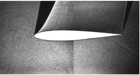
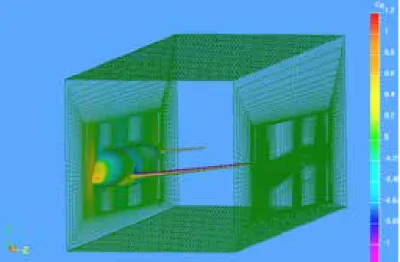
Figure 6 An example of automatically generated grid around a generic transport model (ONERA-M5) inside JAXA 2m x 2m Transonic Wind Tunnel (JAXA TWT1).
5th Symposium on Integrating CFD and Experiments in Aerodynamics (Integration 2012) 3-5 October 2012
JAXA Chofu Aerospace Center, Tokyo, Japan
8
Using the Digital Wind Tunnel, it is possible to count the aerodynamic coefficients of each part of a model, which are constructed from STL data of fuselage, wing, nacelle, pylon, model support, and so on. Therefore, users can examine the influence of each part on aerodynamic characteristics in the pretest CFD calculations.
Before manufacturing a wind tunnel test model and support stings, the digital wind tunnel can be used to evaluate the effects of the configuration of model support on the flowfield around the model. An example of grid generation including two different types of model support, that is, blade-type sting and straight sting, is shown in Fig. 7. Also, corresponding RANS calculation results of pressure distribution (Cp map) on surfaces of the model and sting are shown in Fig. 8. The results of grid generation suggest the robustness of HexaGrid (Fig.
7) while the results of the RANS calculations clearly indicate the model support effect which is seen on the model surface pressure distribution near the junction of the model and support (Fig. 8). Based on these results, the users can choose the best configuration of model support sting without manufacturing several different stings to check the effects of the support configuration during wind tunnel tests. It is significant that this feature of the digital wind tunnel allows aerospace vehicle manufacturers to reduce time and cost for wind tunnel tests during vehicle developments.
(a) Blade-type sting support. (b) Straight sting support.
Figure 7 An example of automatically generated grid including two different model supports around the DLR F6-FX2B model.
(a) Blade-type sting support. (b) Straight sting support.
Figure 8 Calculation results of pressure distribution (Cp) on surfaces of the DLR F6-FX2B model.
A newly-developed feature of the digital wind tunnel is the fluid/structure interaction analysis. As described above, the wind tunnel model is deformed by aerodynamic forces acting on the model during a wind tunnel run.
As shown in Fig. 9, in this interaction analysis, firstly, a CFD analysis using FaSTAR is conducted for an original configuration with no deformation. Secondly, the surface pressure distribution data obtained by CFD are used to calculate the model deformation by a structure analysis using NASTRAN, which has been widely used in the field of structure analysis. In this structure analysis, the model is assumed to be solid, ignoring the
JAXA Special Publication JAXA-SP-13-001E 20
5th Symposium on Integrating CFD and Experiments in Aerodynamics (Integration 2012) 3-5 October 2012
JAXA Chofu Aerospace Center, Tokyo, Japan
9
structure inside the model. Thirdly, based on the model deformation data, the CFD grid on the model surface and in flow field is deformed. Then this loop is repeated until a converged result in terms of both pressure distribution and model deformation is acquired. An example of this analysis for a deformed aircraft wing shown in Fig. 9 indicates that two or three loops of analysis are enough to reach a converged result. Using this feature, we can obtain the pretest CFD data which roughly reflect the model deformation, so the comparison of the pretest CFD data with wind tunnel test data during a wind tunnel test becomes more accurate and reliable, decreasing the need of a further detailed CFD analysis which reflects the model deformation measurement data.
In future, a test model will be manufactured, considering the model deformation at wind tunnel test so as to form the real flight configuration under the aerodynamic load at wind tunnel test.
Loop=0 (initial)
Loop=1 Loop=2 Loop=3 (final)
CD 0.0359 0.0354 0.0354 0.0354
CL 0.5940 0.5867 0.5868 0.5868
Cm -0.1267 -0.1244 -0.1244 -0.1244
•Grey: FSI loop = 0 (initial)
•Light blue: FSI loop = 1
•Yellow: FSI loop = 2
•Red: FSI loop = 3 (final)
CFD analysis (FaSTAR)
Mapping of surface pressure
Structure Analysis (NASTRAN) CFD grid reflecting
model deformation
Convergence check of aerodynamic characteristics
Figure 9 Procedure of fluid/structure interaction analysis.
Acceleration of optical measurement image data processing
Among many types of flow diagnostics in wind tunnels, PIV is one of the measurement techniques which need heavy data processing. Therefore, the acceleration of the PIV data reduction was included in the development of DAHWIN, which is one of key challenges in the improvement of the analog wind tunnel. As shown in Fig. 10, the data processing for a thousand of velocity vector maps usually takes several hours using a PC cluster with eight CPUs while the processing time depends on the choice of data processing algorithm. The goal of the process acceleration in the hybrid wind tunnel is to reduce the processing time by more than one order, resulting in several to ten minutes for the same data processing. As the result, the time needed for PIV becomes not so far from the time for conventional measurement like force balance or pressure measurement, enabling the nearly real-time comparison between the PIV data and corresponding pretest CFD data. To achieve this need, we chose Cell/B. E. as accelerator based on a preliminary evaluation. The system developed with two Cell/B. E. boards resulted in 25 times faster data processing than that of the original data processing system using a PC cluster with eight CPUs [11]. This result means that the goal of processing time less than ten minutes was attained using this accelerator.
Also, acceleration of data processing of PSP measurement [12-13] is being pursued since it is impossible to conduct the processing in a quasi-real-time manner. To overcome this problem, some manual processes such as the detection of position markers on a wind tunnel model surface have to be replaced by new automatic processes.
Model deformation measurement technique using stereo view of position markers on a test model with two cameras was also modified for automation. Similar to PSP, a manual process for finding markers on camera images was successfully automated in order to realize quasi-real-time data reduction.
5th Symposium on Integrating CFD and Experiments in Aerodynamics (Integration 2012) 3-5 October 2012
JAXA Chofu Aerospace Center, Tokyo, Japan
10
7.88s / frame
by x8 CPUs (Pentium D 2.8GHz)
0.32s / frame
by x2 Cell/B.E. Accelerators
at Stereo PIV case
(2k x 2k CCD, 2 cameras, 32x32 pixels, 50% Overlap, FFT)
25 times faster than original system with PC cluster Old
New
(DAHWIN)
(a) Concept (b) Effect on data processing speed Figure 10 Acceleration of the PIV data processing via accelerator.
Examples of Preliminary Applications of DAHWIN
DAHWIN at the final development stage was applied to a series of wind tunnel tests performed at JAXA TWT1 in order to evaluate the usefulness and reliability of the system and find technical items for further improvements towards the complete system. The results are outlined below.
Civil transport-type model test
Firstly, DAHWIN was applied to the wind tunnel test using a civil transport-type standard model (DLR-F6) [14]
as shown in Fig. 11. In this test, optical measurement data of PSP and PIV were obtained as well as six- component aerodynamic force and moment and pointwise pressure data. A total of 42 pretest CFD cases (a maximum cell number of 24 millions) were arranged and performed within two weeks. The force/pressure port data obtained by the measurement apparatus were sent to the system and immediately plotted together with the pretest CFD data as seen in Fig. 11 (c). The pretest CFD datasets that have the same flow properties as those in experimental conditions are automatically chosen by the data search function in the database. Real time comparison of the experimental data with the pretest CFD data enables to check the validity of the measurement data during the test period and to rearrange the plan of the subsequent test cases. The comparison of data acquired by PSP and PIV with CFD data is also possible during testing. By the speed-up of the data reduction as described in the previous chapter, these processed data can be obtained within ten minutes after the measurement. As depicted in Fig. 11 (d), by comparing the PSP data with CFD, we can qualitatively check the degree of measurement error and notice significant problems of the measurement techniques as well as the CFD calculations.
Reentry capsule configuration test
DAHWIN was also applied to a wind tunnel test for a reentry capsule configuration (Fig. 12 (a)) which was conducted as a part of conceptual design of a future space transportation system. Pretest CFD computations of 174 cases (a maximum cell number of 9 millions) were performed within two weeks (Fig. 12 (b)). Computations including a model support system were also made to correct the support interaction effect on the wind tunnel data. At the present system, this was simply done by adding the difference of CFD aerodynamic coefficient data between with and without the support system to the test data. Figure 12 (c) is an example of drag polar plot displayed on the monitoring screen. In this case, it seems that the effect of support interaction was reasonably corrected, using the pretest CFD data. Although in the past, wind tunnel data correction was usually made after the completion of wind tunnel test, it can be made during the test by using DAHWIN. This means that we can readily examine wind tunnel test data without the sting interaction effect.
JAXA Special Publication JAXA-SP-13-001E 22