STUDIES ON THE POST-ECCENTRIC PRETENSIONED PRESTRESSED CONCRETE SHEET PILE
By
Akira WATANABE*
1. INTRODUCTION
Today, there are various materials and their execution methods used for civil engineering works, and new materials and new execution methods are developing year by year. Various methods of sheet pile foundation have also been used.
The author developed the Post-Eccentric Pretensioning Method, which is based on the new idea that releases the prestress in the compressive zone of an ordinary prestressed concrete sheet pile, and studied several aspects of the method.
This paper presents his theoretical and experimental studies. A brief descrip- tion of the PEP Method, the reason why this method has been developed, and what its principles are --- are given in chapter 2 of this paper. Comparison with ordinary PC sheet pile, the execution method of the newly developed sheet pile, and the problems involved are mentioned in chapter 3. In chapter 4, the crosssec- tional forces of the concrete sheet pile are calculated by applying the author's idea to the Chang's equation which is usually used for analyzing piles. In chapter 5, indoor model sheet pile experiments and field experiments are described, and also their results are compared with the calculated results based on the author's
idea.
In this paper, new terminologies are defined as follows.
PEP Method ; An abbreviation for Post-Eccentric Pretensioning Method.
PEP-zation ; To change ordinary pretensioned PC member to PEP mem- ber.
Cutting ; To cut off PC wire in order to ;elease prestress m com- presslve zone.
Live wire ; The wire in which prestress remains.
Bondless Length; The length of wire for which prestress expects to be eliminated.
Preparation for "PEP-zation" ; The various preparations which are necessary for "PEP zation", which must be finished im-
mediately before "Cutting" is performed.
Prestress Re-distribution ; Newly obtained prestress distribution after "Cutting".
' Professor at the Dept. of Civil Engineering Kyushu Institute of Technology
2. DETAILSOFTHEDEVELOPMENTANDTHEPRINCIPIiESOFTHEPEP-METHOD
In a structural member which is subjected to bending moment, tensile and compressive stress respectively appear on either side of the neutral axis. General- ly, prestressed concrete is known as the concrete whose tensile strength is appa- rently increased by introducing pre-compressive stress to the tensile zone of a
concrete member.
In this case, it is very important to introduce a powerful precompressive stress to the zone which will be subjected to tensile stress and, on the contrary, the one, as small as possible, to the zone which will be subjected to compressive stress.
However, in thin concrete members such as ordinary pretensioned PC sheet piles, PC wires are symmetrically arranged, and therefore the prestress distri- butes uniformly in the cross section, because suMcient eccentricity can not be practically obtained due to their thin section, and also the execution method is almost impossible.
Therefore, the induceable prestress is limited not by the necessary amount of stress for the tensile zone of the member but by the allowable compressive stress of the compressive zone.
It is almost impossible to design these thin members to make compressive strength balance with tensile strength. This causes uneconomical results.
Even though the prestress can can be eccentrically introduced on a cross sec- tion as in pretensioned PC beams, PC sleepers, etc., the distribution of the pres- tress does not change throughout the entire beam because of their straightly arranged wires. It also makes their design uneconomical.
It is impossible to obtain the same distribution of prestress, as in a post-
tensioned member having curvilinearly arranged cables, in a member where pre- tensioning method is employed. The author thought that the prestress in the comrpssive zone where compressive stress is unwanted could be eliminated by cutting wires partly and the same distribution of prestress as in post-tensioned members with curvilinearly arranged cables could be obtained if the wires in an ordinarly pretensioned PC member could be cut after concrete sufficiently hardened under the condition that anchoring bond at the ends of wires must be maintained enough.
When the PEP-method is applied for PC sheet piles, "Cutting" must be per- formed after driving the sheet piles in the sites, If not, the driving works wM be very difiicult because the piles, in which "Cutting" is performed, have a ten- dency to be bent easily for their stress eccentricity. The author named this method Post-Eccentric Method (PEP Method).
In the case of PEP sheet pile design, the following two items must be suM-
ciently examined-a) The external bending moment diagram must be precisely known. b) The resisting moment distribution (Prestress Re-distribution) cor- responding to the external bending moment in sheet pile must be obtained by
"Cutting". For this purpose, the exact places of "Cutting" must be found out.
3. THE APPLICATION OF PEP-METHOD
(1) Cutting Method
In order to prevent PC wires from bonding surrounding concrete, the wires in the part where compressive stress is produced by the external moment, that is to say the part where prestess is unwanted, should be covered with blister styrol pipes or coated with grease preceding placing concrete except their both ends for bond anchorage. In this case, the length for bond anchorage must be the transmission length or more. Vinyl pipes are set perpendicularly to PC wires at cutting places in order to make small visible holes from outside, through which PC wires are cut or yielded by gas after hardening concrete. Because the shear- ing resistance of tensioned wire generally decreases, the wires can also be cut even by a cold chisel easily. It is difficult to cut wires by gas when sheet pile is driven deeply into the ground, therefore, a high-voltage electric current can be used for this purpose.
eerl tr
Anchor Small holes
for Cutting
,
1
,
1
1
P,4
o The part where prestress is not required
a.
(Bondless pa?t, Dead wire)
-K
-TF - The part where prestress is required (Bonded part, Live wire)
J d:Thickness of concrete sheet pile
K- A: Transmission length
e : Eccentr{city
(1) Concrete sheet pile (2) Moment diagram (3) Cutting places
Fig. 1. An example of Cutting.
(2) Effectiveness of PEP-Method Application
To examine the effectiveness of the PEP-method by comparing with the ordinary PC sheet piles in which wires are set symmetrically to the neutrical axis of the sheet piles, the resisting moment of SPS 150MMx400rnM sheet pile, (ordinary JIS sheet pile) and PEP sheet pile, whose size is quite the same, are calculated as follows.
a) Notations
b; width of sheet pile '
h; Thickness of sheet pile.
d; Effective depth of section A; Cross-sectional area I; Moment of inertia of section
ye, y. ; Perpendicular distance from the center of gravity of concrete sec- tion to compression and tension and tension fiber respectively epb ep2; Eccentricity of c. g. s. in compressive and tensile zone with regard to c. g. c'. respectively
Api, Ap2; Cross-sectiona! area of wire in compressive and tensile zone res- pectively
P; Total tension in PC wire K; Loss ratio of total tension
Ep, E,; Modulus of elasticity for PC wire and concrete respectively n; Ep/Ec
op,, op,, ; Yield point and tensile strength of PC wire
api.; Allowable tensile stress for PC wire at the stage of the initial prestresslng
ap.; Allowable tensile stress of PC wire
k; Extra coeflicient of creep coefficient of concrete
q, e,; CoeMcient of creep and shrinkage of concrete respectively Aei, Ae2; Area of equivalent section for ordinary concrete sheet pile and PEP sheet pile respectively
Iei, Iez; Moment of inertia of ordinary concrete sheet pile and PEP sheet pile about c. g. c'. respectively
g,;Eccentricity of c. g. c'. with regard to c. g. c. of PEP sheet pile
Pi; Initial prestressing force in PC wire '
opi, a,i; Stress of PC wire and concrete when initial prestressing force is .
glven
apt, o,t; Stress of PC wire and concrete immediately after transfer res- pectively
a,pt; Stress of concrete at the place of said PC wire immediately after transfer
apm, o,. ; Loss of stress of PC wire and concrete due to creep and shrinkage of concrete
ocepo, o,ep. ; Loss of stress at the extreme fiber in compression side and tension side due to creep and shrinkage of concrete
oce; Effective prestress in concrete after deducting losses
o,,,, oce.;Effective prestress at the extreme fiber in compression side and
tension side
op,; Effective prestress in PC wire afer deducting losses
ep3; Eccentricity of c. g. s. in tensile zone of the section of PEP sheet pile with regard to c. g. c'.
y,,, y,.; Perpendicular distance from c. g. c'. to the extreme fiber in com- pression side and tension side of the section of PEP sheet pile r; Radius of gyration of the section of PEP sheet pile
d,,., o,,.; Allowable flexural tensile and compressive stress for compressive zonea
o',.., a,..; Allowable fiexural tensile and compressive stress for tensile zone a'k, ok ; Characteristic compressive and tensile strength prescribed in F. I.
P. standards
o; Compressive strength of concrete at transfer the prestress b) Allowable Stress2'
(1) Concrete
When design load is applied;
Compressive zone of a member a'coa L O.085o't, ocoa L O•29o'k Tensile zone of a member a'cua .L O•085o'k o,ua L O•38o'le For temporary loads applied during construction;
Compressive zone of a member a,.a G O.50a'le
Tensile zone of a member o',u. L O•10atle, a,ua A O.38o'le (2) PC wire
Table 1.
b h
d A
I Yo Yu ep1 ep2 Api Ap2
P
K
Ep Ec n
40 cm 15 cm
12.5 cm 600 cm2
11, 250cm`
7.5 cm 7.5 om
5 cm -5 cm
O.132Å~12= 1.584 cm2 O.132Å~12= 1.584 cm2 1, 800Å~24==43, 200 kg O. 05
2.0Å~106 kg/cm2 4.5Å~10` kg/cm2 4.4
Opv Opu Opia
Ob
ark Ok Otcoa Ocoa Olcua 6cua Ocoa Otcna Ocua
k q
Es
19, 500 kg/cm2 20, OOO kg/cm2 14,OOO kg/cm2 12,OOO kg/cm2 600 kg/cm2 70 kg/cm2 51 kg/cm2 174 kg/cm2 51 kg/cm2 228 kg/cm2 300 kg/cm2
*
År 6o kg/cm2 t ""
228 kg/cm2 1 1.7
3. 4 20Å~10-5 * When design load is applied
*" When temporaryload is applied
When design load is applied; opa,Åq.O•60op.
When prestress is applied; opi.LO.70ap.
c) Design of PC sheet pile
Various values to be used in this design are tabulated below d) Calculation of Resisting Moment
(1) Resisting Moment of Ordinary PC Sheet Pile Aei = A+ (n-1)ZApn=610.8(cm2)
Iei =I+Age2+(n-1)ZApn(epn-ge)2=11,519(cm2) P, =- P(1-K) =-41,04o(kg)
api - Pi/ZAp.-12,955(kg/cm2)Åqopi.-=14,OOO(kg/cm2) a,t == Pi/A,i==67.2(kg/cm2)ÅqO.5a'k
opt = api-na,i==12,659(kg/cm2)
Because prestress is uniform on the entire section, act == OptZApn/Aei=65.7(kg/cm2)
opm nqZa,pt+Epes
U}J, == apt+na,}',-(i+q/2) "= O•103 opm == (apm/apt) xapt==1,304(kg/cmz) a,. is uniform on the entire section, Ocep == Opip2]Apn/Aei==6.8(kg/cm2)
acip == act-acep = Åë?'t-AZ,if!P" " CP'opi,4Pn == (OPt-aAp,ipi)ZAp"
== apeXApn/Aei=58.9(kg/cm2)
op, == (1-apm/apt)opt =opt-apm=11,355(kg/cm2)Åqap.=12,OOO(kg/cm2) Therefore, the resisting moment of an ordinary PC sheet pile can be cal- culated by using the allowable stress for the design load:
M= yl,e'. (oce+o'cua) =1•68(ton-m) ••••••(1)
(2) Resisting Moment of PEP Sheet Pile Ae2 == A+(n-1)Z]Apn==605.4(cm2) ge = (n-1)ZApnepn/Ae2== -O•044(CM) ep3 = : epn- ge = -4.956 (cm)
Ie2 == I+ Age2 + (n - 1) ZAp. (ep3) 2 - 11,383 (cm`)
Yeo = Yo-ge=7•544(CM) Yeu = Yti-ge =m7•456(Cm) Pt - optAp2-20,052(kg)
a,pt == ii, (1+ erP,32) Where, r= ,/7,2/A'L,-2
acpt = J Lt, + Åí'), ttl!,lf3A2 ,, == :'is, + Pi,e,P3 ep3=76.4(kg/cm2)
s
!z2,g.... nqlE]acpt+Epes ,=o.n4 opt opt+no,pt(1+q/2)
ap. = (apa/opt)opt=r1,443(kg/cm2)
Ope = (1dOpm/apt)opt=opt-apq==11,216(kg/cm2)Åqop.==12,OOO(kg/cm2) Pe == apeAp2 = 17,766 (k g)
o,., which is not uniform on the entire cross section, must be calculated as a negatvie eccentric prestress:
o,ipu = Ak{2pm + AP2f,P,epePpm3 'yeu
Ap2opaep3 Ap2opm
e2 + Ie-t T" YeO Oc epo == A
Therefore,
o,,. == o,t. - ocw. = aPf/fl;2 + OPt{!f22eP3 . y,u -o,ep. == ::l'ii2 + Pi,e2P3 . y,.== 87.0(kg/cm2)
Oceo = -AR.e,+ Pff,P3 'yeo=='29.1(kg/cm2)
Therefore, the resisting moment for tensile zone of PEP sheet pile is:
M= ' le'2 (Oceu+O'eua) == 2.10 (tOn- M) ''"'' (2)
Ye"
(3) Effectiveness of PEP-Method Application
By only "Cutting", the resisting moment of PEP sheet pile can be increased, compared with the one of ordinary PC sheet pile, as follows;
2'101;61s'68 •loo=2s.6 o/o (increase)
Moreover, the various loads, which act on a sheet pile before the design load will be applied, can be treated as temporary loads in the design. Therefore, the resisting moment of PEP sheet pile for this case can be calculated by using O.10ok' for o,.. instead of O.085ok'.
For this reason, even before "Cutting", the resisting moment is:
M== - -L'!L' (a,,+a',..) ==1.83(ton-m) Yeu
(4) Problems of PEP Method Appliation
The idea of PEP method seems to be applicable to many other PC members too. The PEP method eliminates th., e prestress on the compressive zone caused by external forces. In this case, the most important thing is that the external force acting on the piles must be precisely known. It is not always possible to re-distribute the prestress corresponding to any kind of external moment diagram, because both ends of the live wires must be anchored and the minimum length of live wires should be longer than 2Z (where Z=transmission length).
For the application of the PEP method, extra labor and costs for cutting and making bondless parts are needed compared with the ordinary one.
The following factors need investigation-whether the bondless parts of the PEP sheet pile cause some defects during the driving works, whether the transmission length in the case of cutting may be longer than the ordinary case.
4 CALCULATION METHOD OF SHEJ]T PIM (AUTHOR'S IDEA)
For the calculation of a sheet piie, many methods have been proposed depend- ing on; how active earth pressure acts on the sheet pile, how the part where active earth pressure which is caused by the displacement of the penetrated por- tion of sheet pile into the ground should be treated.
The author proposed to calculate active earth pressure using Pi=Ca.r.x+
Ca•q and passive with Chang's equation P2===Es•y2 on the assumption that the active earth pressure does not vary even after the sheet pile is transformed.
Therefore,
EI.d4y,
dx,-- Pi ---(K,x-K,) ...(3)
EI.d-d`
.Y-Z ---p, -=-E,•y, ...(4)
Where
Pi, P2: horizontally distributed loads acting on the active and passive earth pressure sides at the arbitrary point of a sheet pile respectively.
yi, y2 : deflection of a sheet pile to the active and passive earth pressure sides at the arbitrary point respectively.
x: distance from the original point.
Ca : coeMcient of active earth pressure.
r: unit weight of soil. q: surcharge EI: fiexural rigidity of a member.
E,: modulus of elasticity of soil Ki=Ca•r, K2==Ca•q The modulus of elasticity of soil is E,== kh.B, kh =o.6gl No•4os 3)
where B: width ef a member, IV: N-value (standard penetration test value), kh:
coeMcient of subgrade reaction
According to Chang's equation, the deflection of driven sheet piles becomes max- imum near the ground surface, and consequently the reaction becomes maximum
at this point.
However, in general case when cohesion becomes zero as in sand ground, P2 becomes zero and this assumption does not satisfy an actual case. In order to
improve the method of application of Chang's equation, Dr. Cho and Dr. Takeshita have proposed to assume a plastic zone near the ground surface around driven sheet piles. However, the auhor set an origin at thedistance of kB'i (k:acoeffi- cient less than 1,B-i=== VEI/El: characteristic length) below the ground surface and assumed that the active earth pressure acts on the upper part of the sheet pile from the origin and the negative earth pressure acts on the lower part from the origin where Chang's equation can be applied. The author named these parts as an active and passive pressure part respectively. The value of kcanbe ob- tained by experiment.
(1) when Active Earth Pressure Acts, a) The Co-ordinate System
...•,-L =
x1 -:
Meq y o y
x
: a
e:ts ca5
pt $ N'
ge a
'-o'-
.cC
: a Ee.ts 8 .ge-".o8
k
pt
e Mo
= RA
A
N"' s x
r -r
Neq -y
y o
Å~
I 8
e fl
ts m5
o8ga
'g Åq
: a
g:• fl
'"om5
o8År"
'a a.
:
f -s.
(1) Self-supported sheet pile (2) Anchored sheet pile Fig. 2. The Co-ordinate system.
b) General Solution
(D Active earth pressure part
yi == aix5+a2x`+Cix+ C2x+ C3x+ C4 ... (5)
ai=-ki/120EI, ct2-K2/24EI
where Ci, C2, C3, C4 : constants of integration @ Passive earth pressure part
y,=e-BX(Cs•cos i?x+C6•sin Bx)+eBX(C7cosBx+CssinBx)
It 'has been found that when the driven length is deeper than zBdi, the dri ven length can be treated as infinite and the error is very smalL Therefor the author assumed the driven length of a sheet pile in the ground as in finite. In the above equation, when x==co, y2 is finite, therefore C7== Cs=O.
Hence, y,=e-BX(Cs cos Bx+C6 sin Bx) ••....(6)
Cs, C6, C7, Cs:constants of integration c) Boundary Conditions
When x=O, for both self-supported sheet pile and anchored sheet pile, Yl=Y2, Ylt===Yllt, Yltt==Y2tt, YIM=Y2M
When x--(h+kB-i)=ei, for self-supported sheet pile, Yitt=O, YiM=O
for anchored sheet pile, yi=O, yi"==-SJIo/EI
d) Basic Formulas for lst, 2nd, 3rd, and 4th Derivatives (D Active earth pressure part
yi = aix5+a2x`+Cix3+C2x2+C3x+C4 y,t !5atix`+4a2x3+3Cix2+2C2x+C3
yi"=20aix3+12a2x2+6Cix+2C2 ••••••(7)
yM == 60aix2+24a2x+6Ci yt"' == 120a!x+24a2
(2) Passive earth pressure part y, == e"eX(CscosBx+C6sinBx)
y', == Be-BX{-C,(cosBx+sinBx)+C6(cosBx-sinBx)
y", -= 2i?2e-BX(C,sinl?x-C6cosBx) ••••••(8)
yM, =- 2B3e-BX{C, (cosi?x-sini9x) + C6 (cosBx+sini9x) } ytt", =: -4B`e-BX(C,cosi9x+C6sinBx)
e) Determination of Constants of Integration (D For the case of self-supported sheet pile
C, == -(10a,e,4+4a,e,) •x
C, == 20ct,e,3+6a,e,2
C3 -- - {10ai e i2 (4 e ,l? -3) + 12af, .t9 ,( t? ,B-1)}/B2
C, - {10a,e,2(2e,B-3) +6ct,e,(e,B-2)}/B3 ••••••(9)
C, - {10ct,e,2(2 .t? ,B-3) +6a,e,(e,B-2)}/B3 C6 = - (20ai .t? i3+6ct2ei2)/B2
(2) For the case of anchored sheet pile
cl = -} B3 ala6 + aa4,aiihai,ai,' a3a5
C, .. - B2 aia6-a3as ala4-a2a3
C3 .= Bala6-a3a{ -a4as+a2a6
aia4-a2a3 .,.,..ao)
C4 ,.. a4a5-a2a6
ala4-a2a3
[
c,=-Z:!I!ZIZ: I
1
C6-ZIZ2IiZIZ5, J
where ai -(eiB)3-3eiB+3
a, -=! e,B{(e,B)2-3e,B+3) a, == 2e,B3
a, = 2e,B3-2B2 as = -3(aiei5+a2ei`)
a, == - (20ct, e ,3 + 12a, e ,2+ 2crs,/EI) "Jn, -== - I:O ca (rz+ q) (ho - z) dz
= ho2(ho+3q)/6
(2) When a Concentrated Load is Applied, a) The Co-ordinate System
H
yo
wta
s
T eq"
N-
NeN,
(1) Self-supported sheet pile (2) Anchored sheet pile Fig. 3. The Co-ordinate system.
b) General Solution and lst, 2nd, 3rd, and 4th Derivatives CD When eim-ÅqÅ~;sl;O, in equatiou (3), Pi-=O. Therefore y, == C,x3+C,x2+C,x+C,
y,, = 3C,xZ+2C,x+ C, y", = 6C,x+2C, yml == 6C, Yttttl = O
(2) Wyhen O;${x, the general solution is the same as equation (8).
... (11)
c) Boundary Conditions
When x-O, for both self-supported sheet pile and anchored sheet pile, Jll =Y2, J7tl= :)2t2, Yltt=Yit, YIM=Y2M
When x=ei, for self-supported sheet plie yi"===O, yiM==-H/EI, Whin x=li, for anchored sheet pile, yi"==-EMo/EI, yi==O.
d) Determination of constant of integration (D For the case of self-supported sheet pile, C,--H/6EI
C, -- He ,/2EI
C, =- H(1- 2B e ,) /2B2EI C, -= H(- B-i+ e ,) /2B2EI C, -= H(- B-i+ e ,) /2B2EI C6 -= -He ,/2B2EI
@ For the case of anchored sheet pile Ci=a3RA+a4
C2=aiRA+a2
C3 - - { (3a3 -2Bai) RA + (3a4 + 2i?a,)} /B2 ...(12) C4 -- ((3a3 + Bai) + (3a4 + Ba2)}/B3
Cs =- {(3a3 + Bai) (3a4 + i?a2)}/B3 C6 - - (aiRA+ a2) /Bz
where
R.--B,S5E-3g-b5i,3.B-,etzg,g-,3,),!3,ge,i,gB,3,e,22,T.2B,2,(-Z.B-),-,
...(13) ai -= - {(hi-h) + e i) /2EI, a, -- He ,/2EI
a3 == 1/6EL a4==-H/6EI
(3) Calculation of The Cross Sectional Forces
Using the above equations, following quantities can be evaluated.
Deflection ... y, Deflection angle ... e==y', Bending moment ... M== -Ely", Shearing stress ... S= Elym, Distributed load ... P=- -ElyM
5 EXPERIMENTS
(1) Indoor Model Experiment
The object of the model experiment is to calculate the resisting moment of a sheet pile by measuring the strains at any arbitrary points of a model sheet pile which had been driven into uniformly compacted soil in an experimental tub and when subjected to a concentrated load. These test results are compared with
those calculated by the author given in chapter 4.
a) A model sheet pile
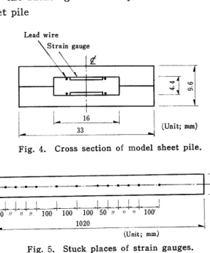
Lead wire Straingauge
Åë
1
(Unit; mm)L,,
L---
Fig. 4. Cross section of model sheet pile.
---+---dH-ke. "c•,
50 ,,, nn 100 100 100 50 it t,
1020 ÅqUnit; mm)
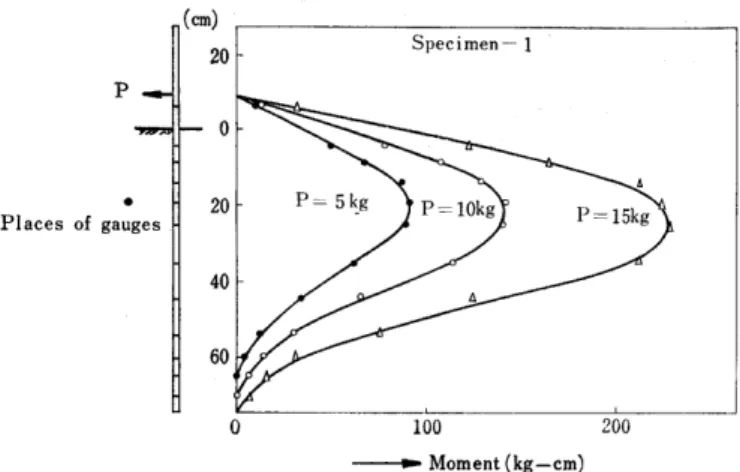
Fig. 5. Stuck places of strain gauges.
Twelve strain-gauges were stuck in the milled grooves of 2.1 mm depth and 16 mm width in two, 33MMx4.7MMxl020MM, ss-41 steel plates by a binding agent PC 12 (gauge cement) as shown in Fig 4 & 5. These two steel plates were stuck by the same binding agent as shown in Fig 4 to form a model sheet pile. The value of EI of the model sheet pile was measured to be 4.8xl05kg cm2.
b) Soil used in the experiment
For the experiment, three different kinds of sand shown in Table 2 were used.
Table 2. The physical properties of soil
Type of Soil Specimen 1 Specimen 2 Specimen 3
Internal Friction Angle
30 22 35
Water Content 5.1%
4.5%
6.4%
Specific Gravity
2. 53 2. 59 2.65
Unit Weight
1.5 t/m3 1.4 t/m3 1.5 t/m3
Remarks Chikugo Riv. Sand Mountain Sand Chikugo Riv.Sand
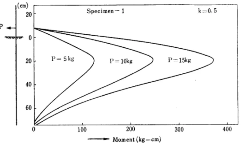
c) The results of experiment
The resisting moment reckoned back from the measured strains are shown in Fig 6•N•Fig 8
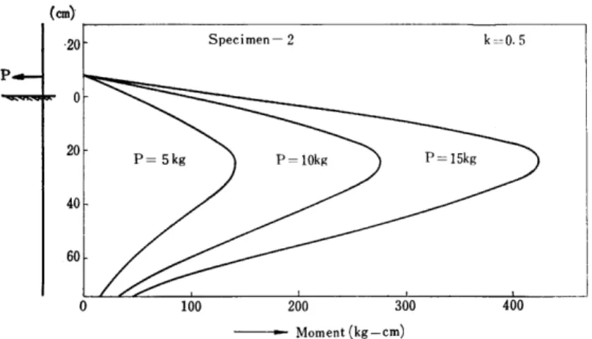
d) Calculated moment based on the authr's idea
Using the prescribed values and equations,the calculated moment (for k=O.4, O.5, O.6) becomes as shown in Fig 9-vFig 17.
P
PIaces of gauges (em]o
o
20
40
60
O 100 200
- Moment (kg-cm)
Fig. 6. Resisting moment diagram (measured)
P
e
Places of gauges
(crn)
.20
20
40
60
O 100 200
. Moment (kg-cm)
, Fig. 7. Resisting moment diagram (measured)
P
e
Places of gauges (em) 20
o
20
40
60
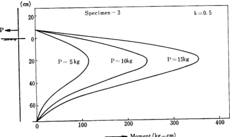
Specimen-3
PL= 5kg p[= lokg p=15kg
O 100 200
- Moment (kg-cm)
Fig. 8. Resisting moment diagram (measured)
'
P P
•(cm)
20
20
40
60
100 200 300
- Moment (kg-cm)
Fig. 9. Resisting moment diagram (calculated)
O 100 200 300 400
-'---' Moment(kg-cm)
Fig. 10. Resisting moment diagram (calculated)
P
(cm)
20
20
40
60
P= 5kg P=10kg P== 15kg
O loO 200 300 400
---. Moment(kg-cm)
Fig. 11. Resisting moment diagram (calculated)
,(en)•
20
20
40
60
(crn)'
.20
o
20
40
60
Specimen-2 k=:O•4
P=5kg P=10kg P=15kg
O 100 200 300 40Q
. Moment(kg-cm)
Fig. 12. Resisting moment diagram (calculated)
O 100 200 300 400
- Moment(kg-cm)
Fig. 13. Resisting moment diagram (calculated)
(cm)
20
20
40
60
Specimen-2 k=O.6
P== 5kg P=10kg P=15kg
O 100 200 300 400 500
----.• Moment(kg-cm)
Fig. 14. Resisting moment diagram (calculated)
(ern)
20
20
40
60
O 100 200 300
---.p Moment(kg-cm)
Fig. 15. Resisting moment diagram (calculated)
(cm)
---•. Moment (kg-cm)
Fig. 16. Resisting moment diagram (calculated)
(cm)
20
20
40
Specimen-3 k= O•6
P=- 5kg P=lokg P=15kg
100 200 300 400
. Moment(kg-cm)
Fig. 17. Resisting moment diagram (calculated)
e) Consideration
Because to obtaining constant soil compaction in field experiment is unsatis- factory, the author resorted toa model sheet pile experiment. In this case,acon- centrated load was applied instead of the active earth pressure. The resisting moment diagrams obtained from the experimental results qualitatively correspond very well with the calculated ones based on thr author's idea. However, the position of the peak of the resisting moment diagram calculated by the author moves downward as the value of k increases regardless of the quantity of external load.
For the same value of k, only the maximum value of resisting moment changes with the increase in external load, but the point of occurence of maximum resist- ing moment does not change. On the other hand, from the experimental results it was found that the point of occurence of maximum resisting moment had a tendency to descend with the increase in external load. The author found out that the value of k changes not only with ground condition but also with the quantity of external load. For instance, in the case of test specimen 1when the external load for a model sheet pile is 15 kg, both peak points of measured mo- ment diagram and the one calculated by the author almost coincide if the value of k is O.5. The value of k obtained by the model sheet pile test might differ from tho one of prototype.
(2) Field Experiment of PEP Sheet Pile
SPS 050 Å~ 4500 mm sheet piles which were PEP-zated are driven into the ground (specific gravity of soil 2.65, water content 5,2 9o, and unit weight 1.5 t/m3) and their strains are measured for both self-supported and anchored conditions when cutting and loading are applied. This is to understand the effect of cutting.
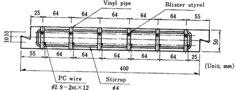
a) A sheet pile section and a specified mix
Vinyl pipe Blister styrol
.O...,
o
Unit; mm)
Åë2•9-2st.Å~12 Åë4
Fig. 18. Cross Section of testing PC sheet pile (Preparation for PEP-Zation is just over and ready for PEP-Zation)
Table 3. Specified mix of concrete Water
W(kg)
Coment C(kg)
Fine Aggregate
S(kg)
Coarse Aggregate
G(kg)
SizeofGMax.
(mm)
Slump (cm)
[Air
Content (%)
w/c
(%)
s/a
(%)
175 l 4go l i
673 1, 122 20 1-2 O.8
l 36 39
b) Cutting places, stuck places of Strain gauges and their numbers eStuck places of strain gauges P oAnchoring point
No.1 2 3 4 5 6 789 101112 13 1415161718 19 20 21
(1) Anchored sheet pile
P
No.1 23 45 6 7 8 9 10 11 12 13 14 15 16 17 18 19 20 21 !!IEU
(2) Se}f-supported sheet pile (Unit; cm)
Fig. 19. Cutting places, stuck places of strain gauges and their numbers.
c) The method of experiment
The author drove SPS 050 Å~ 4500 mm sheet pile 2500 mm into the ground and anchored as shown in Fig 20. As for a self-supported sheet pile, the strain read- ing was set zero when pre-load (425 kg) was applied. The strains at many points on the surface of the sheet pile were measured. Because the scale of the ex- periment was too large and the banking behind the piles was difficult, the author applied concentrated load instead of active earth pressure and surcharge. The measuring was performed under each stage of the following loading conditions.
Cl) For anchored sheet pile a, To make cutting b, 220 kg loading c, 270 kg loading d, 320 kg loading e, 370 kg loading f, 425 kg loading
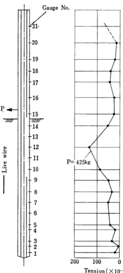
(2) For self-supported sheet pile To make cutting after 425 kg loaded d) The results of experiment
The measured strains of the anchored sheet pile in case of a, c, f and of a self-supported sheet pile are as shown in Fig 20 and Fig 21 respectively.
e) Consideration of the experimental results
For the anchored sheet pile, the re-distribution of prestress in consequence of cutting can be seen as good as expected previously, and the change of strains can be clearly recognized with increase of load (Fig 20). The underground part of a sheet pile must be placed under much more restraint than the upper part of it. However, Fig 20 shows contray to the author's expectation. It is the authors'
Gauge
21
20
, 19
,ls•Anch 17
, 16•
15 14
P
t 13
12 11 10
2 9
'g" 8
o 7 .z
A 6
5 4
3 2 1
N Nx
P='425kg
1P.-.
270kg
Immediate afterCutt
OO100 O,100200
(Å~10-6) Tension Compression(Å~10-6) Fig. 20. Measured strain curves immediately after cutting and when P loaded (Anchored PEP sheet pile)
understanding on this result that some eccentric internal stress might exist due to the differenece of shrinkage of concrete between each side of a sheet pile de- pending on various kinds of ununiformity such as materials, curing, prestress, etc. For a self-supported sheet pile, a good result of cutting can be also obtained (in Fig 21).
6 CONCLUSION
In order to apply the PEP method, the most important thing is to know the external load precisely as prescribed. However, the earth pressure which acts on sheet piles, containing many problems to be solved, needs further investiga- tions. In order to analyze a sheet pile, the author set an origin at the distance of kB-i below the ground surface and assumed that the active earth pressure acts on the upper part of the sheet pile from the origin and the negative earth pres- sure acts on the lower part from the origin where Chang's equation can be applied.
The calculated values agreeded well with the measured one qualitatively. The
G
/21
20
19 18 17
16
P
- 15
14 13
o 12
N
----
g 11
o
År
;ii 10
9 8 7 6 5 4 3
'2 1
Gauge No.
xxx
=425kg
200 100 O
Tension(Å~10"6)
Fig. 21. Measured strain Curve when P loaded after cutting.
calculated values show fairly large values compared with the measured one. As one of the reasons, the author considers that the value of B is a function of both the modulus of elasticity (Es) of soil and the fiexural rigidity (EI) of a mem- ber. Even EI can be measured very accurately, Es is obtained using the empirical formulas Es=kh.B, kh=O.691NO'`06, which contain rather rough assumptions. For this reason, it seems preferable to obtain Es directly by Pressiometer method.
Because it has been recognized from the results of experiments that the value of k is a function of not only ground condition but also external load, the value of k for sheet pile design should be obtained depending on soil condition and de- sign load.
The author applied the PEP method to pretensioned PC sheet pile as a first step. By using this method, the prestress in the compressive zone where com- pressive stress is unwanted can be eliminated and the same distribution of pres- tress as in post-tensioned member with curviliniarly arranged cable can be ob- tained.
Therefore the author believes that this method can be applicable widely.
Especially, if this method is applied for a thin slab, it will bring the effectiveness into full play. Othor applications of the PEP method are now under study.
The PEP method is not an extraordinary method and is not so novel as to stand out above various other methods which have been commonly used. This method is only based on the idea that eliminates unwanted stress in the compressive zone of PC member by cutting the wires. However, it must not be only the author who is astonished by the unexpected quantity of wire and member section econo- mized by adapting the small device.
There are two means of utilization,...an active utilization and a passive utiliza- tion. It is well-known that there is generally a tendency to attach importance to the former, but no importance to the latter. Because the idea of this PEP method belongs to the latter, it seems that this idea has not been put to practical use even though it has been recognized. Therefore the author finally confirmed the importance of the passive utilization.
It must be recognized again that the best way to design PC member eco- nomically is to completely follow the basic principle of prestressing..."Introduce larger compressive stress in the part of the member where tensile stress will be given rise to in the future by external moment, and on the contrary, introduce larger tensile stress in the part where compressive stress will be given rise to".
C`ACKNOWLEDGEMENT"
The author is deeply indebted to Mr. Shoichiro Maehara and Mr. Hirofumi Kato for much contribution.
The author wishes to thank Dr. Shunji Inomata for his many helpful com- ments and criticisms.
REIERENCES
1) Akira Watanabe, Hirofumi Kato, Shoichiro Maehara : The Collected Gists of The Lectures, The Meeting of The Seibu Branch of The Japan Society of Civil Engineers.
February, 1968
2) Japan Society of Civil Engineers: A Specification for The Design and The Execution of Works of Prestressed Concrete. 1961.
3) Masami Fukuoka, Kazuma Uto: A Study on The Measurement of The Value of k of The Ground in Horizontal Direction by Using a Boring Hole. Soil and Foundation, Special Issue 1, 1959,
4) Takashi Cho; A Calculation Method for The Horizontal Resistance of Rigidly Fixed Piles at Their Heads, Civil Engineering Techniques, 16-5, 1961.
5) J. Takeshita: Studies on Piles Subjected toHorizontal Load, The Hokkaido Branch of The Japan Society of Civil Engineers, Technical Papers, 18, 1962.