超伝導トランスの直流動作による高安定磁界の発生に関する研究
16560245
平成16年度~平成18年度科学研究費補助金
( 基盤研究(C) )研究成果報告書
平成19年4月 研究代表者 小田部荘司
九州工業大学 情報工学部 助教授
<はしがき>
本研究では超伝導トランスを用いて高安定の直流電流を得ることができるかどうか、その 結果高安定の磁界を発生することができるか検証を行うことが目的である。超電導トラン スの二次側の電流を抵抗体による電圧測定による抵抗法、磁界を検出するホール素子によ るホール素子法、そしてピックアップコイルによるピックアップコイル法の3方法を試み た。その結果、1ppmには及ばないが、高精度の直流電流を得ることができた。この方法は 今後、NMRやMRIなどに応用されていく可能性がある。
研究組織
研究代表者: 小田部荘司 (九州工業大学情報工学部助教授)
研究分担者: 木内勝 (九州工業大学情報工学部助手)
研究協力者: 倪宝栄 (福岡工業大学工学部教授)
交付決定額
(配分額) (金額単位:円)
直接経費 間接経費 合計
平成16年度 500,000 0 500,000 平成17年度 1,000,000 0 1,000,000 平成18年度 500,000 0 500,000
総計 2,000,000 0 2,000,000
研究発表
(1) 学会誌等(発表者名、テーマ名、学会誌名、巻号、年月日)
“Generation of highly stable DC current by using a superconducting transformer”, B. Ni, S. Hakoda, E. S. Otabe, M. Kiuchi, Journal of Physics: Conference Series, Volume 43、pp.837~840、(2006)
(2) 口頭発表(発表者名、テーマ名、学会等名、年月日)
“Generation of DC Current with High-Stability by Using a Superconducting Transformer”,
B. Ni, E. S. Otabe, M. Kiuchi, 7th European Conference on Applied Superconductivity (EUCAS), TU-P2-28, pp.170, Vienna, Austria (Sep. 2005)
「小型超伝導トランスを用いた定電流の発生」
箱田晋輔,倪 宝栄,木内 勝,小田部荘司、応用物理学会九州支部学術講演会、31巻、1Ep-1、
pp.99、福岡工業大学、(2005.11)
研究成果
研究目的
本研究では、超伝導トランスを用いて直流動作を実現し、これによって高い安定性のある 磁界の発生を目指すことを目的としている。これは交流損失計測のために試作した超伝導 トランスの試験を行っているときに1Hzという低周波数で動作できることが分かり、ある 程度の時間内であれば直流動作ができるのではないかと考えられたからである。実際に手 持ちのトランスで外部回路や制御無しでも数秒は電流一定を保つことができ、また一次電 流を制御をすることによりさらに長時間直流電流を得られるということが分かっている。
本格的に直流動作を利用するためには、専用の超伝導トランスを試作し実証することが重 要である。
超伝導トランスの直流動作により次のような応用例が可能になると考えられる。まず計測 では低温において長時間に亘って大電流を長し続けることができると、酸化物超伝導体の 安定性の問題解決に寄与できると考えられる。低温を保ったまま大電流を長時間流すこと は、室温からの銅ケーブルの発熱があり困難である。酸化物超伝導体は金属系超伝導体と 違って、臨界電流より低い電流を通電しているときでも徐々に温度が上がる不安定性が報 告されている。したがって、長時間に亘って電流を流し続けることができるので、たとえ ば超伝導電力ケーブルの安定性の研究に役に立つと考えられる。
他の重要な応用例として高い磁界を高い精度で一定に保つ必要がある NMR 用マグネット がある。20 Tを越える中心磁界を持つNMR用超伝導マグネットでは最内層マグネットに Bi-2212線材を使っている。Bi-2212は4.2 K程度の低温では20 Tを越える磁界でも電流 を通電することができるためである。しかし酸化物超伝導体特有の磁束クリープ現象によ り、永久電流モードで動作させているにもかかわらず磁界が時間とともに減衰してしまう という問題点がある。実際に物質材料機構のNMR マグネットでは 930~MHz まで実現で きたが、さらに高い磁界を要求する1 GHzは最内層Bi-2212マグネットの安定性に問題が あり実現ができていない。ここで直流動作できる超伝導トランスを用いて外部からのコン トロールにより磁界の減衰を軽減することができる。電流トランスにより一次側入力電流 は小さくてすみ、二次側電流は大電流を得られるので小型で大きな磁界を得ることができ る。さらに安定性については外部からのコントロールが可能となる。つまり、超伝導材料 のみではできない応用が、電子回路などの他の技術を補完的に用いることにより実現でき ると考えられる。
NMR用の超伝導マグネットにおいて一定の磁界を出すための工夫として、フラックスポン
プがあり例えばMITのIwasaらによって研究されている。しかしその動作のためにはいく つかの超伝導永久電流スイッチをコントロールする必要があり、一回の動作に数十秒かか るという大きな欠点がある。超伝導トランスの直流動作では連続して大電流を通電できる ことから、フラックスポンプに代わる技術として用いられる可能性がある。具体的には、
バイアス磁界には永久電流モードにより安定して磁界を出せる従来の金属系超伝導体を 用いる。最内挿では磁界が高くて金属系超伝導体は用いることができず、酸化物超電導体 を用いるが、これをトランス結合させることにより、磁束クリープの電流減少分について は外部から与えることにする。
本研究では、直流動作をさせるための超伝導トランスを試作する。そして直流動作を高い 電流値、長時間、安定に得られるように制御をする方法を確立する。そしてそれを元にし て、超伝導トランスを超伝導マグネットに組み込むことにより、一定の磁界を長時間安定 に得られることを実証する。さらに得られた知見より他の応用について提言を行なう。
研究方法および結果
初年度はこれまでに製作した超伝導トランスに、パーソナルコンピュータとAD/DA変換ボ ードを中心とした制御装置を付加して、トランスの直流動作を試み、これを理論解析する。
この試験により次年度以降に行う、新しい超伝導トランスの試作への知見を得ることを目 的とする。
これまで試作してきた超伝導トランスは超伝導試料の交流通電損失を測定するために設計 されている。つまり一次側と二次側の巻線比が極端であり、一次側に小電流を流したとき に二次側に大電流が流せるようにしている。本来、このような設計の超伝導トランスは高 精度で長時間の直流動作には向いていない。しかし外部に簡便な制御装置をつけるだけで、
通常の常伝導トランスでは考えられないレベルの精度で長時間の直流動作ができると期待 できる。初年度では、まず外部の制御装置を確立して直流動作が不利である現状の超伝導 トランスにおいても、ある程度の直流動作ができることを実証することを目的としている。
直流動作に最適な超伝導トランスの設計及び製作は次年度以降に行う。
これまで行ってきた制御では二次側の電流をデジタルボルトメーターで測定し、そのデー タを GPIB を使ってコンピューターに取り込み、簡単なモデルより次のステップの一次側 の電流を計算し、また GPIB を使って一次側の電流源をコントロールするものであった。
GPIBはデータの転送速度が遅いので制御の間隔は100ミリ秒程度とかなり遅かった。そこ で、備品に計上しているコンピューターとAD/DA変換ボードを購入し、制御速度を数ミリ 秒程度に向上させることにより精度の高い制御を可能とする。まず二次側の電流を直接
AD/DA変換ボードにより計測を行う。次にコンピューターによりモデルにしたがった計算 を行い次のステップの一次側の電流を求めて、同じくAD/DA変換ボードを用いて電流源を 直接コントロールする。
このようにコンピューターとAD/DA変換ボードを組み合わせると、簡単なプログラムの作 成により自由度の高い制御を実現することができる。また従来は速度が問題となっていた が、最近の技術では全体の制御装置を電子回路で作ることに比べても、十分な速度で制御 ができるようになっている。
電流の測定にはこれまで二次側の巻線に配置したロゴスキーコイルと超伝導体両端の電圧 から測定を行ってきたが、ホール素子による測定も考えられるので、この方法についても 検討を行うこととする。この際もAD/DA変換ボードにより直接の電流測定ができる。
現有している超伝導トランスは 500A 級の液体窒素中で動作するものと、1000A 級の冷凍 機冷却型がある。これらの二つの超伝導トランスにこの制御装置を用いた直流動作を試み ることにし、制御のモデルの妥当性などについて検討することにする。
これまでの解析では簡単な等価回路から理論値を出していたが、細かい電流の挙動につい てはうまく説明することができなかった。これはトランスの直流動作では通常の交流動作 とは違って、鉄心が偏磁し、等価的なインピーダンスが電流により異なるためだと予想さ れた。このことを確かめるために新たにモデルを作り、このモデルに基づいた解析を行う ことで、実際の二次側電流の細かい挙動を説明することを試みる。これにより制御がさら に精度の高いものに変更することができると考えられる。
また、最近有限要素法を用いた超伝導体内の電磁現象について調べてきている。これは市 販の有限要素法ソフトを拡張することによって実現できている。たとえば交流電流を通電 している際の超伝導体内の電流分布や磁束密度について計算することができ、これから交 流損失を見積っている。また外部から交流磁界を与えたときに超伝導体にどのように磁束 が侵入するか計算することもできている。このようなことから、本研究の超伝導トランス についても直流動作を行っているときに、どのように電流が流れるか有限要素法を用いて 細かく検討をすることが可能であると考えられる。この結果より制御をどのようにしたら いいのかという知見が得られるものと期待できる。
実験には設計値で二次側に500Aまで通電できるトランスを用いた。二次側は銅板と超伝導 テープにより短絡した。一次側の電流はシャント抵抗を用い、また二次側の電流はあらか じめロゴスキーコイルにより較正したホール素子からの電圧と、二次側の銅板の両端の電
圧を用いて評価を行った。トランスは液体窒素中で冷却して実験を行った。
二次側の電流を AD コンバータを通じてコンピュータに取り込み、次の一次側の電流値の 計算をおこなったあとに、DAコンバータを通じて一次側の電流源に送り、電流を制御した。
その結果、二次電流の最大値、精度やその維持時間はかなり制限されるものの、一定値に することができた。またその様子は簡単な回路方程式により説明することができたが、完 全ではなかった。この理由は、超伝導トランスの結合係数が電流値により変化するためで はないかと考えられる。
平成17年度以降においては前年までの知見を利用して、直流動作に向いた超伝導トランス の設計および製作を行う。さらにそれを用いた試験を行い、その利用法についての検討を する。ここでの設計ではNMRで使用されることを想定して、超伝導マグネットの中で重畳 する磁界を作るという目的で超伝導トランスを設計および製作する。
これまで超伝導トランスは小型のもので 3種類以上、中型のもので1 つを設計製作してい る。これらはすべて二次側に100—1000 Aを得るために設計したものであり、二次側の巻 き数が一次側に比べて極端に少なく、インダクタンスが小さい。本研究では二次側に直流 電流を流すために二次側のインダクタンスがある程度大きい方が望ましい。
バイアス超伝導マグネットの外部に結合部分を置くことにより、バイアス磁界の影響を抑 えることができる。超伝導トランスの線材には市販されている Bi-2223 超伝導線材を用い る。
実際に超伝導トランスを製作する。このための超伝導線材や金属部品を消耗品として計上 している。さらに既存の14~T超伝導マグネットの中心にこの超伝導トランスを設置して、
試験および評価を行う。この試験装置によりどのくらいの精度で磁界を一定に保つことが できるかどうかを評価し、NMRの最内層マグネットの制御につかえるかどうかを検討する。
以上は平成17 年度に主に行うが、平成18 年度は試作された超伝導トランスと制御装置で の制御の方法を検討し、より高い精度で磁界を一定に保つことができるかどうかを検証す る。具体的には超伝導トランスを単体で制御することに比べて、14~T超伝導マグネットの バイアス磁界の中に超伝導トランスが置かれている状況では環境が異なるので、制御に影 響が出てくる可能性がある。したがっていくつかのパラメータを考慮して制御の方法をす る必要があると考えられる。
これらの結果をまとめることにより、実際のNMR用超伝導マグネットの構成における、超
伝導トランスの直流動作による高安定磁界の発生について提言を行う。
平成17年度には次のような結果を得た。超伝導トランスの一次側は0.2mmφの銅線であり、
200回巻き線をした。二次側にはΒι−2223銀シース多芯テープ材を用いた。このテープ材の 77Κ、自己磁界における臨界電流は80Α以上である。テープ材は巻き線による劣化のない巻 き線径で18回巻いた。今回の超伝導トランスでは巻き数比を極端にしておらずまた臨界電 流も小さいの、二次側に流れる最大電流はあまり大きくないが、結合係数はよくなると期 待できる。
二次側の通電電流は低抵抗のシャントを挿入してその両端に発生する電流から測定した。
この電流値を一定にするために、一次側に流す電流を制御する。制御にはPID制御を用い た。その結果、80Αの電流を10秒程度維持することができた。制御は全体で4つの状態に分 けることができる。最初は目標の80Αを達成するために急速に一次側の電流が増えている段 階である。次に10秒程度の電流を一定にできる時間がある。この間では一次側の電流は徐々 に上昇していく。一次側の電流には限度があるので、やがて80Αを保てなくなり、やや二次 側の電流は減少する。さらに一次側の電流が12Αに達したところでそれ以上電流値を上げな いので、二次側の電流は急激に小さくなる。この結果制御時間は10秒程度の時間となった。
また制御の精度は0.4%であり、1ppmというレベルからはかなり離れている。
平成18年度においてはこれらの知見を生かしてより精度を上げる工夫をした。精度を上 げるためには、二次側の電流を精度良く測定する必要がある。そこで、二次側に発生す る磁界をホール素子とピックアップコイルにより測定し、その測定値を元に一次側の電 流を制御する。この結果、ホール素子よりもピックアップコイルの方が精度よく電流を 観測することができ、二次側の電流をより一定にすることができた。
研究のまとめ
今回の研究を通じて超伝導トランスの直流動作を行うことができることを実証するこ とができた。また高安定磁界の発生については、いくつかの方法を提案し、実際に実施 した。今後、これらの結果をさまざまな超伝導機器に応用することができると考えられ る。たとえばNMRやMRIなどの高精度な磁界安定を求められる機器において、今回 の知見が生かされる可能性がある。
Generation of highly stable DC current by using a superconducting transformer
B Ni1, 3, S Hakoda1, E S Otabe2 and M Kiuchi2
1 Department of Life, Environment and Materials Science, Fukuoka Institute of Technology, Fukuoka 811-0295, Japan
2 Faculty of Computer Science and Systems Engineering, Kyushu Institute of Technology, Iizuka 820-8502, Japan
E-mail: [email protected]
Abstract. The purpose of this study is to generate a highly stable DC current by using a superconducting transformer. For the first trial stage, a 100 A class superconducting transformer was designed and fabricated for operation at the temperature of liquid nitrogen.
The secondary coil of the transformer was wound with a superconducting Bi-2223 tape, and the turn ratio of the primary and secondary windings was about 11:1, which brought an output current of about 80 A by a small varying control current. The control system was constructed with a PC, an AD/DA conversion PCI board and a small current supply. The primary input current was controlled by a normal PID control program. The secondary output current was evaluated by measuring the voltage on a low resistivity shunt. As the result of this study, it was suggested that in the case of small impedance in secondary winding circuit, the DC output current with high stability can be obtained by applying an easy control algorithm to the program running on the controlling PC.
1. Introduction
Recently, many kinds of applications of high-Tc superconductors to electric and electronic area have been studied. One of the noticeable studies is the application of superconducting AC power transformer, on which several achievements have been reported [1]. The results gave us hints on a new application of superconducting oxide materials to a DC power transformer. The purpose of this study is aimed to generate a highly stable DC current by using a superconducting transformer. The large DC current over several hundred amperes with high stability is expected to be used for the generation of highly precise and large magnetic field in the NMR system and other applications. For example, DC output current of the superconducting transformer generates a highly precise magnetic field, which may become an alternative method to the flux pump system for the compensation of decremental persistent current in a HTS magnet system.
For the first trial stage, a 100 A class superconducting transformer was designed and fabricated under the concepts of low-cost, compact and large-capacity system. A compact superconducting transformer for AC use was reported by Otabe et al. [2], in which the availability of the system was successfully clarified. In this study, we designed the system with the target of DC use, referring to the
3 Baorong Ni, 3-30-1 Wajirohigashi, Higashi-ku, Fukuoka 811-0295, Japan. Tel: ++81-92-6063789
results reported on the systems for AC use. For the concept of low-cost, we constructed the control system based on a PC, instead of using an exclusive apparatus. In this paper, the details of transformer fabrication and system construction were mentioned. An evaluation and discussion were given based on the structure of the superconducting transformer for highly precise control, and the optimization of the control system.
2. Fabrication
The specifications of the primary and secondary coils of the transformer are listed in table 1. The turn ratio of the primary and secondary windings was about 11:1, which brought an output current of about 80 A by a small varying control current. The secondary coil was wound with a commercial
superconducting Bi-2223 tape. The specifications of the tape are listed in table 2. Since the allowable bending diameter of the Bi-2223 tape is about 50 mm, the secondary coil was wound on a bakelite bobbin with a slightly larger diameter. In order to increase the mutual inductance M between the primary and secondary coils of the transformer, a normal iron core with a cross-section of 9.6 × 10⁻⁴
m2 was built in. The whole size of the transformer was about 80 mm × 100 mm × 140 mm and the weight was about 1.5 kg. The transformer was designed for operation at the temperature of liquid nitrogen. Figure 1 shows the image of the transformer.
The control system was constructed with a PC, a 16-bit AD/DA conversion PCI board and a small current supply. The output current (secondary current) of the transformer was evaluated by measuring the voltage on a low resistivity shunt, which was serially connected in secondary winding circuit. The control current (primary current) of transformer was controlled by a normal PID control program written and executed in LabVIEW graphical programming environment (National Instruments) on a PC. With this controlled primary current, the output current was fixed at the target value.
In order to realize an accurate control, the accuracy of the voltage measurement on the shunt is quite important, which means that the shunt having large resistivity is favorable. However, for the purpose of ensuring a small superconducting current damping in the secondary winding circuit, the resistivity value must be kept low enough. In this study, we used a bridge-shaped copper block for the
Table 1. Coil specifications of the superconducting transformer.
primary secondary
number of turns 200 18
kind of wires copper (0.2mmφ) Bi-2223 tape
diameter of bobbin [mm] 50 59
height of bobbin [mm] 48 48
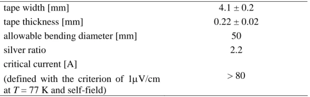
Table 2. Specifications of Bi-2223 tape used for the superconducting transformer.
tape width [mm] 4.1 ± 0.2
tape thickness [mm] 0.22 ± 0.02
allowable bending diameter [mm] 50
silver ratio 2.2
critical current [A]
(defined with the criterion of 1µV/cm at T = 77 K and self-field)
> 80
shunt, which the resistivity was 4.89 × 10⁻⁶Ω at 77K (see figure 1). The voltage on the shunt was amplified to 1000 times by using an isolation amplifier.
3. Results and Discussion
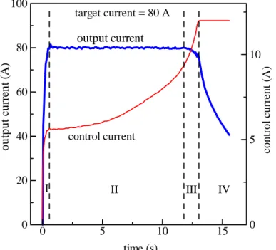
Figure 2 shows the result of the controlled output current (thick line) under the variation of the control current (thin line). The target value of output current was set at 80 A, which is close to the critical current of the Bi-2223 tape used in the transformer. The process of the output current control can be separated into 4 phases along the flow of time, as shown by I – IV in figure 2.
At first phase (phase I), a rapid increase in output current was shown, accompany with a rapid increase in control current. When output current reached the target value, 80 A, then it was controlled as fixed to the target value, by increasing the control current gradually (phase II). Although the variation of output current around target value was controlled within a range less than ± 0.4 %, there is
Figure 1. Image of the superconducting transformer. The size is about 80 mm × 100 mm × 140 mm and the weight is about 1.5 kg. The copper bridge on the upper side is used as a shunt for measuring the output current.
Figure 2. Result of the controlled output current (thick line) under the variation of the control current (thin line).
output current (A) control current (A)
I II III IV
output current
control current
time (s) target current = 80 A
0 5 10 15
0 20 40 60 80 100
0 5 10
still a lot of space to reduce the variation to a level below 1 ppm. The large variation was considered to be caused by the electrical noise in the voltage measurement on the shunt, which was used in the feedback control. On the other hand, long duration of phase II is an important factor, while it was limited to a value of about 10 seconds in this study. This is due to the large resistivity serially connected in secondary winding circuit. If we assume the self-inductance and the resistivity in secondary winding circuit are L and R, respectively, we can get the equation (1):
d0
d 0 ,
d d
i
L i M Ri
t+ t − = (1) where i and i0 are output current and control current, respectively. Since the time differential of i should be zero in phase II, then,
d0
d . M i
i= R t (2) This means that if we use a small increase of control current to generate a large output current, R should be a sufficient low value, e.g., below 10-9 Ω.
For phase III, the increase of control current could no longer keep the output current at the target value. The output current gradually decreased out of control. This was partially caused by a heating effect on Bi-2223 tape, due to the current in primary winding, which may bring a deterioration of critical current in Bi-2223 tape. Finally, the control current reached to the upper limit value, and the output current decayed in the time constant of L/R (phase IV).
4. Summary
In this study, a low-cost and compact superconducting transformer for DC current generation was fabricated. The secondary coil of the transformer was wound with a superconducting Bi-2223 tape.
The control system was constructed with a PC, an AD/DA conversion PCI board and a small current supply, and the control program was written and executed with LabVIEW. As the result of this study, a comparatively stable output current up to 80 A was obtained, with a variation from the target value less than ± 0.4%. In the case of small impedance in secondary winding circuit, it is possible to generate a DC current with high stability and sufficient persistence, by using this system.
Acknowledgments
This work was partially supported by a Grant-in-Aid for Science Research (Project no. 16560245) granted by the Ministry of Education, Culture, Sports, Science and Technology of Japan.
References
[1] Funaki K, Iwakuma M, Takeo M, Yamafuji K, Suehiro J, Hara M, Konno M, Kasagawa Y, Okubo K, Yasukawa Y, Nose S, Ueyama M, Hayashi K and Sato K 1996 Design and construction of a 500 kVA-class oxide superconducting power transformer cooled by liquid nitrogen Proc. Of ICEC 16/ICMC Kitakyushu p. 1009
[2] Otabe E S, Morizane Y, Matsushita T, Fujikami J and Ohmatsu K 2000 Small current transformer using oxide superconductor for transport AC loss measurement Advances in Cryogenic Engineering vol 45 p. 713
Generation of DC current with high-stability by using a superconducting transformer B Ni 1 , S Hakoda 1 , E S Otabe 2 and M Kiuchi 2 1 Fukuoka Institute of Technology, Japan 2 Kyushu Institute of Technology, Japan
Introduction Many studies on applications of high Tc superconductors to AC power transformer. Æ Hints to the application of DC use. Possible to generate a highly stable DC current by using a superconducting transformer. Objective Design and fabricate a 100 A class D C
superconducting transformer under the concept of low-cost, compact and powerful system.
Circuit Diagram
Specifications of transformer primary secondary number of turns 200 18 kind of wires copper (0.2mm φ ) Bi-2223 tape diameter of bobbin [mm] 50 59 height of bobbin [mm] 48 48
Image of the transformer Resistor with a resistivity of 5 x 10 -6 Ω Iron core • Size: 80 mm x 100 mm x 140 mm • Weight: 1.5 kg
AC transforming characteristic
primary current (A) secondary current (A)frequency = 100 Hz time (s)-10
010 00.020.040.060.08
-100-50
050
100 20Hz 50Hz 100Hz 200Hz 500Hz primary current (A)
se con dar y cu rren t (A )
T = 77 K 0.1110
110
100