A Systematic Inspection Approach to Verifying and Validating Formal Specifications based on Specification Animation and Traceability
著者 LI Mo
著者別名 李 漠
その他のタイトル 仕様アニメーションとトレーサビリティーに基づく 形式仕様の検証と実証の系統的な検査アプローチ page range 1‑226
year 2015‑09‑15 学位授与番号 32675甲第367号 学位授与年月日 2015‑09‑15
学位名 博士(理学)
学位授与機関 法政大学 (Hosei University)
URL http://doi.org/10.15002/00012841
仕様アニメーションとトレーサビリティー に基づく形式仕様の検証と実証の系統的な
検査アプローチ
A Systematic Inspection Approach to Verifying and Validating Formal Specifications based on
Specification Animation and Traceability
by Mo Li
A dissertation submitted in partial satisfaction of the requirements for the degree of
Doctor of Philosophy
Graduate School of Computer and Information Sciences HOSEI UNIVERSITY
September 2015
Advisor: Professor Shaoying Liu, Hosei University
Contents
0 Preface 13
1 Introduction 17
1.1 Formal Methods and Formal Engineering Methods . . . 20
1.1.1 Formal Methods . . . 20
1.1.2 Formal Engineering Methods . . . 22
1.2 Speci…cation Veri…cation and Validation Techniques . . . 23
1.2.1 Formal Proof . . . 23
1.2.2 Conventional Inspection . . . 24
1.2.3 Animation . . . 24
1.2.4 Model Checking . . . 25
1.3 Our Solution: Inspection based on Speci…cation Animation and Traceability . . . 26
1.4 Summary . . . 29
2 Brief Introduction of Structured Object-oriented Formal Language 30 2.1 Informal Speci…cation . . . 31
2.2 Formal Speci…cation . . . 32
2.3 Summary . . . 36
3 Overview of the Inspection Based on Speci…cation Animation and Traceability 37 3.1 The Outline of IBSAT . . . 37
3.1.1 System Functional Scenario-based Speci…cation Animation . . . 37
3.1.2 Traceability-based Checklist . . . 39
3.1.3 Formal Speci…cation Inspection . . . 40
3.2 Background of the Case Study . . . 42
3.3 Summary . . . 43
4 Formal Speci…cation Animation 44
4.1 CDFD Decomposition . . . 45
4.2 Extracting System Scenarios . . . 49
4.2.1 Sequence Structure . . . 50
4.2.2 Parallel Structure . . . 52
4.2.3 Loop Structure . . . 55
4.2.4 Limitation of the Algorithm . . . 60
4.2.5 Combinatorial Explorsion . . . 62
4.3 Animating Speci…cations . . . 64
4.3.1 Animation Process . . . 64
4.3.2 Test Suite Selection . . . 67
4.3.3 Execution of System Functional Scenarios . . . 72
4.4 Summary . . . 74
5 Traceability of Speci…cations 75 5.1 Explicit and Implicit Requirements . . . 75
5.2 Requirement Items . . . 76
5.3 Inspection Targets . . . 78
5.4 Construction of Traceability . . . 84
5.5 Summary . . . 88
6 Formal Speci…cation Inspection using IBSAT 89 6.1 The Four Aspects of Inspection Targets . . . 89
6.1.1 Necessity . . . 90
6.1.2 Appropriateness . . . 91
6.1.3 Correctness . . . 95
6.1.4 Completeness . . . 98
6.2 Checklist and Inspection Procedure . . . 100
6.3 Feedback . . . 103
6.4 Case Study . . . 104
6.5 Summary . . . 109
7 Tool Support for SOFL Speci…cation Construction and Veri…cation 110 7.1 Design and Implementation . . . 110
7.2 Functions Provided in the Framework . . . 113
7.2.1 Speci…cation Organization . . . 113
7.2.2 Informal Speci…cation Editor . . . 115
7.2.3 Semiformal and Formal Speci…cations Editor . . . 116
7.2.4 Keeping Consistency between the CDFD and the Module . . . 119
7.2.5 System Functional Scenarios Generation . . . 122
7.2.6 Animation . . . 123
7.2.7 Inspection . . . 124
7.2.8 Integrated Functions . . . 126
7.3 Evaluation of System Scenario Generation Function . . . 127
7.3.1 Loop Structures . . . 127
7.3.2 Evaluation of Combinatorial Explosion . . . 129
7.4 Experience of Using the Tool . . . 133
7.5 Summary . . . 133
8 Experiment 134 8.1 Experiment Settings . . . 135
8.1.1 Background of the Target Speci…cations . . . 135
8.1.2 Subjects . . . 137
8.1.3 Categories of Bugs . . . 138
8.2 Experiment Implementation . . . 143
8.2.1 The Documents for Traditional Checklist-based Inspection . . . 143
8.2.2 The Documents for IBSAT . . . 144
8.3 Results Analysis . . . 148
8.3.1 Comparison between Di¤erent Groups . . . 149
8.3.2 The Unfound Bugs . . . 157
8.3.3 Possible Improvements . . . 163
8.4 Findings in the Experiment . . . 165
8.5 Threats . . . 166
8.6 Summary . . . 167
9 Related Work 168 9.1 Animation . . . 168
9.2 Inspection . . . 171
9.3 Traceability . . . 174
9.4 Summary . . . 176
10 Conclusion and Future Work 177 10.1 Conclusion . . . 177
10.2 Future work . . . 178
10.2.1 Research on Inspection Method . . . 178
10.2.2 Research on Supporting Framework . . . 179
11 Appendix: Documents Used in the Experiment 193
List of Figures
1.1 The principle of formal methods . . . 21
2.1 The informal speci…cation of a simpli…ed ATM software . . . 33
2.2 The formal speci…cation of module “SYSTEM_ATM” . . . 34
2.3 The CDFD of a simpli…ed ATM software . . . 35
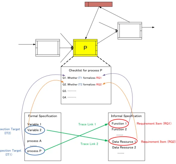
3.1 The relations among basic concepts of our inspection approach . . . 41
4.1 The decomposition of a single process . . . 46
4.2 The decomposition of the CDFD of the simpli…ed ATM . . . 48
4.3 Derivation of system scenarios from the CDFD with sequence structure . . . 53
4.4 Derivation of system scenarios from the CDFD with parallel structure . . . 54
4.5 CDFD with loop structure . . . 56
4.6 CDFD with nested loop . . . 61
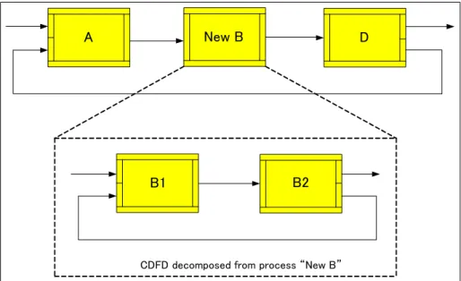
4.7 A new CDFD by combining process “B” and “C” . . . 61
4.8 Decomposing the process “New B” . . . 62
4.9 Sequential Loops . . . 63
4.10 Two CDFDs with the same number of processes . . . 63
4.11 The de…nition of process “Check_Password” . . . 66
4.12 The de…nition of process “Withdraw” . . . 71
4.13 The animation process of a system functional scenario . . . 73
5.1 The dependence chain . . . 82
7.1 The major functions provided by the supporting framework . . . 112
7.2 The architecture of the framework . . . 113
7.3 The structure of …le system used in the framework . . . 114
7.4 The “Hierarchy Explorer” used to manipulate the SOFL project . . . 115
7.5 The user interface for constructing informal speci…cation . . . 116
7.6 The user interface for constructing formal speci…cation . . . 117
7.7 Creating new module by decomposing a process . . . 118
7.8 The drop-down list in the “Formal Editor” . . . 119
7.9 The snapshot of generating system scenarios . . . 123
7.10 The snapshot of formal speci…cation animation . . . 124
7.11 The snapshot of formal speci…cation inspection . . . 125
7.12 The “evaluator” for operation scenarios . . . 126
7.13 Invoking the integrated pattern system function . . . 127
7.14 Invoking the integrated parser function . . . 128
7.15 System scenario generation from a CDFD with single loop . . . 128
7.16 System scenario generation from a CDFD with sequential loops . . . 129
7.17 System scenario generation from a CDFD with 30 processes and no loop structure . . . 130
7.18 The main memory usage of generating system scenarios from a CDFD with 30 processes and no loop structure . . . 130
7.19 System scenario generation from a CDFD with 30 processes and one loop structure . . . 131
7.20 System scenario generation from a CDFD with 10 processes and two loop structures . . . 132
8.1 CDFD of the traget formal speci…cation . . . 136
8.2 The process “Deposit” in the target formal speci…cation with bugs . . . 139
8.3 The process “Withdraw” in the target formal speci…cation with bugs . . . 139
8.4 The process “Receive_Bank_Comm” in the target formal speci…cation with bugs . . . 140
8.5 The document used in the experiment . . . 145
8.6 The document used in the experiment (contiune) . . . 146
8.7 Part of the process “Buy” in the target formal spceci…cation with bugs . . . 159
8.8 The process “Bank_Account_Authorize” in the target formal speci…cation with bugs . . . 161
List of Tables
4.1 Three operation scenarios in the process . . . 67
4.2 Input data generation algorithm . . . 69
4.3 Test suites for a normal function . . . 74
5.1 The inspection targets of a speci…c system scenario . . . 83
5.2 Relations between speci…cation items . . . 85
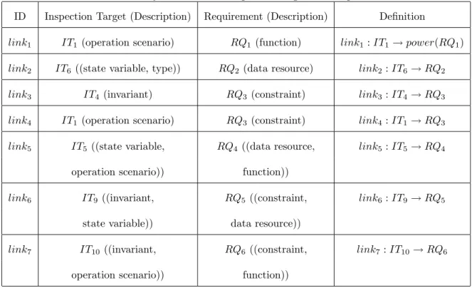
5.3 Traceability rules between inspection targets and requirement items . . . 86
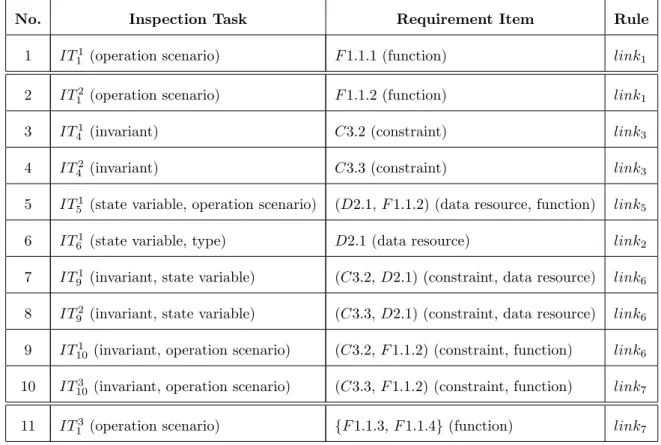
5.4 The trace links between the inspection targets and the requirement items . . . 87
6.1 Typical appropriateness questions for di¤erent inspection targets . . . 93
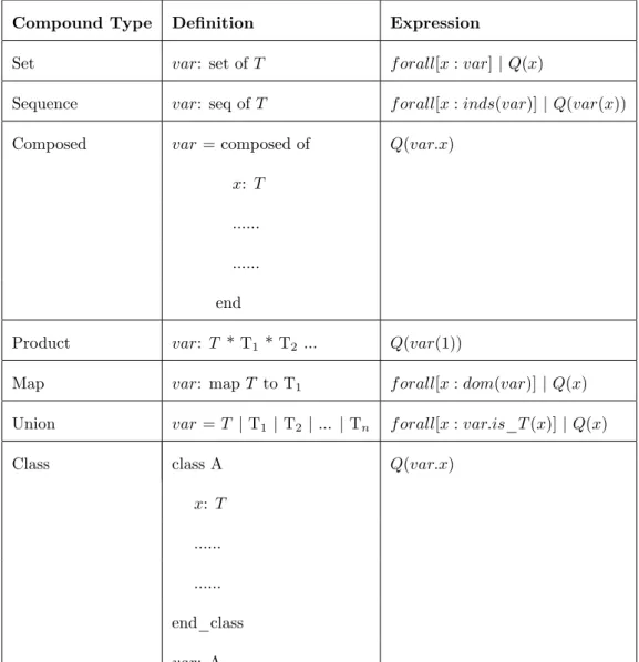
6.2 Extracting restricted variables from the variables with compound type . . . 97
6.3 Checklist for inspection . . . 101
6.4 The results of inspecting the necessity property . . . 105
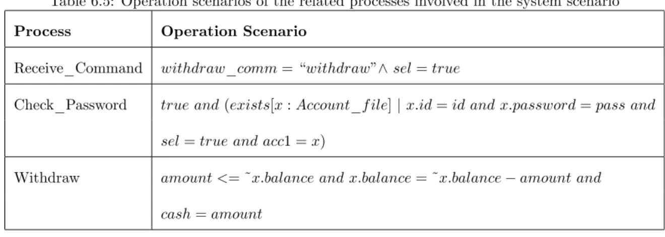
6.5 Operation scenarios of the related processes involved in the system scenario . . . 106
6.6 The inspection results of the system scenario . . . 107
6.7 The inspection results of the system scenario (continue) . . . 108
7.1 The changes that may a¤ect the consistency . . . 121
8.1 The requirement items and inspection targets in the experiment . . . 136
8.2 The three groups in the experiment . . . 137
8.3 The detailed classi…cations of bugs . . . 139
8.4 The categroies of bugs . . . 143
8.5 The detailed results made by the subjects in Group A . . . 150
8.6 The detailed results made by the subjects in Group B . . . 151
8.7 The detailed results made by the subjects in Group C . . . 152
8.8 The inspection results of each group and revelant statistics . . . 153
8.9 The number of bugs found in domain dimension . . . 156
8.10 The number of bugs found in consistency dimension . . . 156
8.11 The summary of Group B under detailed bug classi…cation . . . 157
ACKNOWLEDGMENTS
First and foremost, I want express my sincere gratitude to my supervisor Prof. Shaoying Liu for his various tremendous supports throughout my research work. He always pays great attentions to the research process of mine and gives me many useful suggestions in doing research. Whenever I encountered problems in my research, I could get timely and useful helps from him. Although he is busy at work, he is always patient in discussing with me, correcting my writings, and leading me to the right direction. He also shares some of his own experience which can bene…t my research and daily life. His enthusiasm for research inspired me and all the students in our laboratory, and his encouragement helps me to overcome a lot of di¢ culties.
I would like to appreciate all the professors in the faculty for their various kind helps during my study. I want to give my special thanks to the professors who have taught me directly in classes. They help me to expand my knowledge in di¤erent …elds.
I appreciate the student colleagues in the laboratory for their helps in both research and daily life. I also appreciate the students who participated in my experiment for their cooperation.
I want give my thanks to the sta¤ in the administration o¢ ce for their constant assistance in my campus life.
Finally, I want to thank my family for their understanding and support.
Publications
Journal Paper
1. Mo Li and Shaoying Liu, “Integrating Animation-Based Inspection into Formal Design Speci…cation Con- struction for Reliable Software Systems,”IEEE Transactions on Reliability, 2015 (Conditional acceptance).
International Conference Papers
1. Mo Li and Shaoying Liu, “Automated Functional Scenarios-Based Formal Speci…cation Animation,”Pro- ceedings of 19th Asia-Paci…c Software Engineering Conference (APSEC), IEEE Press, Hong Kong, 4-7 Dec.
2012, pp.107-115.
2. Mo Li and Shaoying Liu, “Traceability-Based Formal Speci…cation Inspection,”Proceedings of Eighth In- ternational Conference on Software Security and Reliability (SERE), IEEE Press, San Francisco, USA, 30 June-2 July, 2014, pp.167-176.
3. Mo Li and Shaoying Liu, “Reviewing Formal Speci…cation for Validation Using Animation and Trace Links,”
Proceedings of 21th Asia-Paci…c Software Engineering Conference (APSEC), IEEE Press, Jeju, Korea, 1-4 Dec., 2014, pp.286-293.
4. Mo Li and Shaoying Liu, “Tool Support for Rigorous Formal Speci…cation Inspection,”Proceedings of IEEE 17th International Conference on Computational Science and Engineering (CSE), IEEE Press, Chengdu, China, 19-21 Dec., 2014, pp.729-734.
International Workshop Papers
1. Mo Li and Shaoying Liu, “Design and Implementation of a Tool for Specifying Speci…cation in SOFL,”
Proceedings of 2nd International Workshop on SOFL of 14th International Conference on Formal Engineering Methods, LNCS 7787 Springer, Kyoto, Japan, 13th Nov. 2012, pp. 44-55.
2. Mo Li and Shaoying Liu, “SOFL Speci…cation Animation with Tool Support,”Proceedings of 3rd Interna- tional Workshop on SOFL + MSVL, LNCS 8332, Springer, Queenstown, New Zealand, 29th Oct. 2013, pp.
118-131.
ABSTRACT
The role of requirements analysis in assuring the quality of software products has been well recognized and writing formal speci…cations has been suggested to be e¤ective in both helping developers understand user’s requirements and enhancing the quality of the requirements documentation. However, like the other activities in software development, the construction of formal speci…cations is usually error-prone in practice. Although many methods have been proposed for error detection, few of them o¤er systematic and practical approaches to employ the user’s requirements in the detection process. How to e¤ectively detect the defects contained in a formal speci…cation before it is delivered for implementation is still a challenge.
In this dissertation, we present a novel inspection approach for formal speci…cation veri…cation and validation.
The approach features the combination of a speci…cation animation-based reading technique and a traceability- based checklist. The animation method adopted is called system functional scenario-based animation method (SFSBAM) which dynamically presents the operational behaviors of the formal speci…cation by means of “exe- cuting” corresponding system scenarios. Each system scenario represents an independent operational behavior and is presented as a sequence of processes. The inspector is guided to read through the formal speci…cation by following its “execution”and required to check the formal speci…cation items of a speci…c process involved in each step of the “execution” against the informal speci…cation based on a traceability-based checklist. The informal speci…cation documents the user’s requirements using a structured natural language and it is the foundation for building the formal speci…cation. The traceability is presented by the relations between the requirement items in the informal speci…cation and their corresponding formalizations in the formal speci…cation. In the checklist, the relations are used to raise speci…c questions to examine formal speci…cation items for keeping the consistency between the informal and formal speci…cations.
We also present a prototype tool that supports the entire procedure of our speci…cation inspection approach.
Moreover, an experiment has been conducted to evaluate the performance of our inspection approach, and the results indicate that our approach is more e¤ective than the traditional checklisted-based inspection method.
3. Mo Li and Shaoying Liu, “Adopting Variable Dependency in Animation for Presenting the Behavior of Process,”Proceedings of 4th International Workshop on SOFL + MSVL, LNCS, Springer, Luxembourg, 6th Nov. 2014 (to appear).
Others
1. Mo Li and Shaoying Liu, “Using Real Data to Animate SOFL Formal Speci…cations Automatically,”Pro- ceedings of IPSJ/SIGSE Winter Workshop 2014 in Oarai, 23-24 Jan. 2014, pp. 39-40.
Preface
Nowadays software is deployed in almost all the important systems related to our daily life, such as TV sets, refrigerators, washing machines, automobiles, trains, and airplanes. The quality of the software is therefore crucial to the dependability of the systems. The failure of the software may lead to catastrophic disasters. For this reason, developing reliable software systems has attracted considerable attention from both industry and research communities.
In the traditional software engineering model, requirements analysis is considered as the …rst phase in the development process. As a result of the phase, a document called requirements speci…cation is usually constructed, which describes the expected functionality of the system and de…nes the capabilities of the provided software.
Since the requirements speci…cation will be used as a foundation for the following development phases, its quality can signi…cantly a¤ect the quality of the …nal software system.
According to IEEE guide to software requirements speci…cations [1], a good requirements speci…cation should be unambiguous. However, since the traditional requirements speci…cations are usually written in natural languages (e.g., Japanese, English), the ambiguities cannot be easily removed. To this end, writing formal speci…cations has been suggested to be an e¤ective way to help developers understand user’s requirements and produce accurate requirements documentation. Formal speci…cations use mathematically-based formal notations to precisely de…ne the requirements and therefore remove the ambiguity from the speci…cations. However, like other activities in soft- ware development, the construction of formal speci…cations is usually error-prone in practice. Therefore, detecting errors contained in a formal speci…cation before it is delivered for implementation is very important.
Speci…cation veri…cation and validation is the activity to detect defects and eliminate inconsistencies from the requirements speci…cation for enhancing its quality. On the basis of our study of the literature, we …nd that there are three main kinds of methods for verifying and validating the formal speci…cations. One is to formally prove the formal speci…cation. This usually requires that the developer have a strong mathematical background and high skills in manipulating mathematical formulas. The proof process is also usually complex and time-consuming, which can hardly be adopted in practice. Another kind of method is to execute the formal speci…cation by
either translating it into an executable program or using a …nite state machine to traverse the state space of the speci…cation. But we should notice that the errors found in the execution can only show the existence of defects but there is no speci…c instruction to guide the developer to …nd the defects. The third kind of method is to review the formal speci…cation statically. Using this method, humans are required to read through the speci…cation in order to discover defects. Unfortunately, lack of e¤ective reading techniques limits the e¤ectiveness of such methods in detecting errors. Furthermore, few of existing methods provide precise and systematic guidance for utilizing informal speci…cations in the defect detection process.
In this dissertation, we propose a novel inspection approach for verifying and validating formal speci…cations.
In the approach, an animation method called system functional scenario-based animation method is adopted as reading technique to guide the inspector to read through the formal speci…cation, and a traceability-based checklist is utilized to instruct the inspector to examine the consistency between the informal and formal speci…cations. A supporting tool is developed to support the entire inspection process, and an experiment has been conducted to evaluate the performance of our inspection approach.
Major contributions of our inspection approach are brie‡y introduced below:
1. SFSBAM to support reading in speci…cation inspection
A system functional scenario-based animation method (SFSBAM) is proposed and elaborated. In this method, all of the possible system functional scenarios are …rst derived from the formal speci…cation. Each system scenario presents an independent operational behavior de…ned in the speci…cation. In the animation, each system scenario is dynamically presented in a condition data ‡ow diagram. In the inspection, inspectors are guided to read through the formal speci…cation by following the animation process.
2. Traceability-based checklist to support speci…cation inspection
In our inspection approach, a formal speci…cation is constructed based on an informal speci…cation which documents the user’s requirements by using a structured natural language. The traceability between the two speci…cations is presented by the relations between the requirement items in the informal speci…cation and their corresponding formalizations in the formal speci…cation. In order to formally de…ne the relations, we
…rst formally de…ne the categories of requirement items and formal speci…cation items. Then, traceability
rules between requirement items and formal speci…cation items are formally de…ned. These relations are used to raise speci…c questions for each formal speci…cation item for examining the consistency between the informal and formal speci…cations.
3. A prototype tool to support speci…cations construction and inspection
To support the speci…cation inspection process, a prototype tool is developed. The major interesting functionality of the tool includes supporting the construction of both informal and formal speci…cations, automatically deriving all possible system functional scenarios from the formal speci…cation, carrying out animation as a reading technique to support the speci…cation inspection, and managing all of the related data …les.
4. An experiment
To evaluate the e¤ectiveness of our inspection approach, an experiment is conducted. In the experiment, the subjects are required to inspect the same formal speci…cation by using either our inspection approach or the traditional checklist-based inspection method. The results indicate that our inspection method is more e¤ective than traditional checklist-based inspection method to help the inspector detect defects contained in the formal speci…cation. We analyze the reasons that lead to the results and point out our …ndings.
Chapter 1 presents the background and the motivation of our research, including the basic terminologies and concepts, the weakness of existing methods, our solution and the contributions of our research.
Chapter 2introduces the SOFL informal and formal speci…cations, which will be used as the target speci…ca- tions for illustrating the main principles of our research.
Chapter 3 …rst gives an overview of our inspection approach and related techniques, and then introduces the background of the case study that will be used to explain the methods and techniques in the following chapters.
Chapter 4 explains the detailed techniques of our system functional scenario-based animation method. The formal de…nition of the system scenario is given and the algorithm used to automatically extract possible system scenarios is explained. We describe the animation procedure and use examples to illustrate how to carry out the animation.
Chapter 5 describes the traceability between SOFL informal and formal speci…cations. The categories of requirement items and formal speci…cation items are …rst formally de…ned, and the traceability rules for building trace links between requirement items and corresponding formal speci…cation speci…cation items are then discussed.
The trace links will be used to construct traceability-based checklist for speci…cation inspection.
Chapter 6 demonstrates how the speci…cation inspection is carried out. We …rst discuss the four aspects that need to be checked for each formal speci…cation item. Then the structure of a traceability-based checklist is introduced. We discuss the feedback to the questions on the checklist and use a case study to demonstrate the entire inspection process.
Chapter 7 elaborates on the prototype tool that supports the inspection for SOFL formal speci…cation. We explain the design of the tool and introduce its major functions.
Chapter 8reports an experiment conducted to evaluate the e¤ectiveness of our inspection approach. We …rst point out the purpose of the experiment, and then introduce the experiment settings. We analyze the experiment results and make several conclusions based on the analysis. We also present several important …ndings based on our analysis of the experiment result.
Chapter 9 summarizes the research work related to our approach from three aspects: animation, inspection, and traceability. The novelty of our inspection approach is illustrated through the comparison with these related work.
Chapter 10is the last chapter of this dissertation, which gives the conclusion of the research work presented in the dissertation and points out the future research directions.
Chapter 1
Introduction
Software has become an important part of our modern life style. The smart phone we use to communicate with others works on software; the personal computer we use to …nish our daily job works on software; the automobile we use to transfer to di¤erent places is controlled by software. From the international company to single person, we all bene…t from the e¢ ciency and convenience brought by the usage of software. Since more and more services rely on software, the failure of software system development may lead to great loses [2]. For those safety-critical systems, like control system of powerstation, public transportation, etc., software failures cause not only the loss of money, but also the people’s life [3] [4]. How to develop a reliable software system is considered as a critical problem in software engineering.
Software engineeringis the study of how to develop and maintain a software system in a systematic approach [5].
Many models have been proposed to manage the software development process. One of the well known models is waterfall model [6], that separates the entire software development life-cycle into …ve phases. As indicated by this model, the …rst phase in the software development is therequirements analysis phase. The major task of this phase is to collect and document user’s requirements. It is the most critical phase since it lays the foundation for the subsequent phases, includingdesign,implementation, testing, andmaintenance. The artifact of the requirements analysis phase is usually a software documentation calledrequirements speci…cation, which describes the expected functions of the system and de…nes the capabilities of the provided software [7]. Whether a requirements speci…- cation is well written can signi…cantly a¤ect the quality of the …nal software system and the success of a software project [8].
Since the requirements speci…cation will be inherited by the following development phases, any defects in the speci…cation would lead to an incorrect software product and the failure of the development project. Verner et
al. in [9] declared that the failures of 73% projects in their 70 failed projects sample are caused by the lack of adequate and correct requirements information. An incorrect product or a failure project may cause many losses.
These losses include not only the money, but also the time and the human resources. If the development project is hosted by a software company, the failure will also damage the company’s reputation. In order to avoid the failures caused by the incorrect requirements, it is usually cost-e¤ective to remove the errors in the requirements speci…cation as earlier as possible. The earlier the errors in the speci…cation can be found, the more e¤orts and costs can be saved in the following development. Glass states that requirements errors are the most expensive defects to …x during production but the cheapest to …x early in development [10]. Boehm even claimed that it is possible to save up to 100 : 1 by …nding and …xing requirements problems early rather than late in the development life-cycle. In addition to the savings, detecting errors in early phase also has signi…cant payo¤s in improving the reliability, maintainability, and human engineering of the …nal product [11].
Speci…cation veri…cation and validation is the activity to detect errors and remove inconsistencies from the speci…cation for enhancing its quality [11] [12]. Theoretically, veri…cation and validation are two di¤erent activities [13]. Veri…cation is to check whether the speci…cation is right, namely complying with some standards or criteria, and validation is the activity to examine whether the speci…cation satis…es the user’s requirements. However, these two activities are almost inseparable in practice since a person (analyst, designer, stakeholder, etc.) must use all his knowledge simultaneously to examine a requirements speci…cation, no matter the knowledge is needed for validation or needed for veri…cation.
Several techniques have already been proposed in di¤erent literatures for verifying and validating requirements speci…cations [14] [15] [16]. The frequently used techniques include speci…cation review, interviews, conventional inspection [17], simulation, animation, formal proof, model checking, and prototyping. Some of these techniques can be applied to both informal and formal requirements speci…cations, and some can be applied to only formal requirements speci…cations. By informal requirements speci…cation, we mean the requirements speci…cation writ- ten in natural languages (like English, Japanese). The techniques can be used to verify and validate informal speci…cations contain reviews, interviews, inspection, etc. However, the inherent characteristics of the informal speci…cation restrict the e¤ectiveness and e¢ ciency of the veri…cation and validation techniques from two aspects:
The ambiguity in the informal speci…cation cannot be easily removed
The ambiguity of the informal speci…cation is usually caused by the usage of natural languages. The words with multiple meanings and the lack of rigorous sentence structures in the natural language may lead to di¤erent interpretations of the same speci…cation content. Moreover, the readers with di¤erent backgrounds and domain knowledge may interpret the same speci…cation in di¤erent ways.
Some techniques do exist to reduce the ambiguity in the informal speci…cation. For example, the interview technique mentioned above requires an interviewer to discuss a speci…cation with the person who write it for identifying potential blind spots, misunderstandings [11]. The result of an interview is a requirements speci…cation in which the interviewer and the originator have the same understanding. But, the interview cannot guarantee other speci…cation users (developer, tester, operator, maintainer) interpret the speci…cation in the same way as the interviewer and the originator.
The lack of automated tool support a¤ects the e¢ ciency of veri…cation and validation
Whether automated tool support can be provided a¤ects the e¢ ciency of veri…cation and validation signi…cantly.
The tool support can be either fully automated or partly automated. In order to achieve full automation, two conditions must be satis…ed. One is that the procedure of veri…cation and validation can be automatically carried out. And the other is that the necessary information used in veri…cation and validation can be automatically extracted from the requirements speci…cation. Whether the procedure can be automatically performed depends on the technique itself. If the procedure of a veri…cation and validation technique cannot be automatically performed, the support to this technique can only be partly automated. Note that the validation activity is to check whether the speci…cation satis…es the user’s requirements. Even the technical procedure can be fully automated, the …nal decision must be made by human.
For example, the speci…cation review requires someone other than the originator, called reviewer, to read through the speci…cation for identifying potential problems. Since the reviewer usually has di¤erent point of views, it is possible to …nd blind spots or misconceptions that the speci…cation developer might have made. In general, the reading process must be done by human and cannot be completed automatically. To e¢ ciently support the reviewing process, the support tool is expected to automatically provide the information that can help the reviewer to make judgement. For instance, when reading the description of a speci…c function in the speci…cation,
the reviewer need to refer to the related data items or constraints documented in the requirements speci…cation to help him make decisions. If the supporting tool cannot automatically extract such information, the reviewer has to read through the speci…cation trying to …nd the related information. This will inevitably reduce the e¢ ciency of the tool support and the speci…cation review process. Unfortunately, since the informal requirements speci…cations lack well de…ned format and involve ambiguities for interpretations, automated information extraction from informal speci…cations is almost impossible.
Comparing to informal speci…cations, formal speci…cations use mathematically-based formal notations to pre- cisely de…ne the requirements and therefore remove the ambiguity from the speci…cations [18] [19] [20] [21]. How- ever, since the formal speci…cations construction process for large systems is usually error-prone, veri…cation and validation are also necessary to enhance its quality. Automated tool support for formal speci…cation veri…cation and validation becomes possible because of the usage of formal notations. In this dissertation, we focus on the technique for verifying and validating the formal speci…cation and its support tool.
1.1 Formal Methods and Formal Engineering Methods
Formal requirements speci…cation is constructed during the procedure of applying formal methods to collect and document user’s requirements. In this section, we …rst introduce the formal methods and related concepts, then we introduce a more practical formal method called formal engineering method.
1.1.1 Formal Methods
The concept formal method refers to systematic approaches to using mathematical methods for analysis, design, development, and veri…cation of computer and software systems [22]. Di¤erent formal methods have been proposed in literatures, such as VDM (Vienna Development Method) [23], Z [24], B-Method [25]. These formal methods have been used to develop di¤erent systems [26] [27] [28] [29] to enhance the quality of software products.
The core of formal methods is the formal requirements speci…cation written in mathematically-based formal language. Since the formal language has precise syntax and semantics, the formal speci…cation can precisely de…ne the functions of the expected system without any ambiguity. The …rst version of formal speci…cation is usually constructed by formalizing the user’s requirements. The requirements can be collected through the communications
User’s Requirement
Formal Specification 1
Formal Specification 2
Formal Specification n
Program
…
refinement
refinement
refinement
refinement formalization
verification and validation
verification and validation
verification and validation
verification and validation
verification and validation
Figure 1.1: The principle of formal methods
with users. Then, the …rst version of formal speci…cation is evolved through continuous re…nement until the …nal program is implemented. Figure 1.1 shows the principle of applying formal method to software development.
Before the developer can re…ne the current formal speci…cation into next version, he has to make sure the speci…cation is correct and all user’s requirements are appropriately formalized. As indicated in Figure 1.1, this is achieved through veri…cation and validation. Veri…cation is a technique aiming to examine the correctness and internal consistency of the speci…cation, and validation is a technique to check whether the software system formalized in the speci…cation satis…es the user’s requirements. Although the e¤ectiveness of validation heavily relies on human decisions, the ideal veri…cation of formal speci…cations can be rigorous, formal, and fully automated.
Moreover, since the formalism is well established in the formal speci…cation, using tool to automatically support the validation process becomes possible.
Although the formal methods provide a theoretically e¤ective solution for developing reliable software systems, the e¤ectiveness of formal methods in realistic systems development is controversial [30] [31] [32]. However, the latest survey conducted by Woodcock and his colleagues in paper [33] indicates that some industrial groups work-
ing in the domain of safety critical systems …nd formal speci…cations useful in helping them obtain su¢ cient understanding of the envisaged system. While recognizing the useful e¤ect of formalization, we …nd that only mathematically-based notation is unlikely to be widely used in industrial projects in which most of the practition- ers do not have a strong mathematical background and their development activities are almost always constrained by limited budget and time [34]. A more practical formal method, known as Structured Object-oriented Formal Language (SOFL), has therefore been developed for improvement [35] [36].
1.1.2 Formal Engineering Methods
SOFL is not only a formal speci…cation language, but also a systematic formal approach for software development.
This approach is called formal engineering method to distinguish from the traditional formal methods. The characteristics of formal engineering methods include the integration of formal speci…cations into the modeling process, the combination of formal notations with graphical notations, and automated tool support for writing formal speci…cations and carrying out inspections and testing. [37] [38] [39] [40] [41] [42] [43].
As a formal speci…cation language, SOFL uses a formalized data ‡ow diagram notation calledcondition data ‡ow diagram (CDFD) to describe the architecture of the system and text-based mechanism calledmodule to formally de…ne the components of the CDFD, including data ‡ows, data stores, and processes (or operations in general term), using a formal notation similar to Vienna Development Method - Speci…cation Language (VDM-SL) [44].
Comparing to the traditional formal speci…cations, like VDM-SL, B-Method, PVS [45], such an architecture-based approach to constructing formal speci…cations has found to be suitable for abstract design of software systems and helpful in reducing changes in formal speci…cations [46] [35] [47] [48].
Although the use of the visualized notation CDFD enhances the comprehensibility of SOFL formal speci…cations for communication, formalizing the user’s requirements directly into the formal speci…cation still faces di¢ culty at the detailed level because of the complexity of the mathematical expressions used in the module. Therefore, a three-step approach for constructing formal speci…cations is introduced as part of SOFL [36]. In the three-step approach, an informal speci…cation written in a structured natural language is …rst constructed. The informal speci…cation documents the user’s requirements from three aspects: functions, data resources, and constraints.
Then, a semi-formal speci…cation is constructed based on the three aspects of the requirements. In the semi-formal
speci…cation, the data resources and constraints are formally de…ned as necessary data structures and invariants, respectively. The functions in the informal speci…cation are de…ned as processes. The interface of each process is formally de…ned, but the functionality of the process is described in a natural language. In the last step, the informal functionality described in the semi-formal speci…cation is formalized for constructing a formal speci…cation.
Unlike the traditional formal methods, the SOFL three-step approach provides a practical and systematic way for creating formal speci…cations via speci…cation evolution. Since we intend to use the SOFL formal speci…cation to demonstrate our methodology in this dissertation, a detailed introduction is presented in Chapter 2.
1.2 Specification Verification and Validation Techniques
To construct a good formal speci…cation as a fundamental for implementation, veri…cation and validation must be performed to enhance the quality of the speci…cation. Several techniques for formal speci…cation veri…cation and validation have been proposed in literatures. In this section, we summarize some well studied techniques and point out their weakness.
1.2.1 Formal Proof
Formal proof [46], also called formal veri…cation, is adopted in the traditional formal methods to guarantee the correctness of formal speci…cations. The basic idea of formal proof is using logical reasoning to prove the consistency of a formal speci…cation. It provides a fundamental technique for verifying formal speci…cation and is considered as the most rigorous approach for veri…cation. However, the cost-e¤ectiveness and practicality of formal proof are controversial [49] [50].
The proof process is usually complex and time-consuming, and in general cannot be fully automated. Since the modi…cations of requirements and formal speci…cations are almost inevitable in the development process, revising formal proofs brings additional costs. Therefore, using formal proof for large scale and complex system is challenging.
The process of formal proof can be supported by theorem provers, such as PVS [45], B-Toolkit [51], and Z/EVES [52]. But using theorem provers usually requires a high level of expertise. The failure of a proof may result from the use of inappropriate proof tactics, inference rules, or existence of errors in the consistency properties.
This means the failure of a proof cannot indicate the incorrectness of the speci…cation, since it can also be caused by incorrect proof process. Moreover, the formal proof is perhaps not necessarily as e¤ective as existing techniques in design and implementation phases. In [49], Hall states that proof is no more a guarantee of correctness than testing, and in many cases far less of one.
Because of its complexity, time-consuming, and the doubt of its cost-e¤ectiveness, formal proof is rarely used in industry [33].
1.2.2 Conventional Inspection
Inspection is a static analysis technique used for the veri…cation and validation of software artifacts, which can be requirements speci…cation, design, or program. The inspection is …rst proposed in IBM by Fagan in [17], and has been widely used [53] [54] [55] [56] [57] [58]. In an inspection, the target software artifact is …rst distributed to a team of inspectors that have di¤erent perspectives. The inspectors are asked to read the article based on a checklist for identifying possible faults. The checklist contains questions specifying the problems and properties of the target artifact that need to be checked. It serves as a reminder to the inspector to avoid any missing of major defects. As long as the inspectors …nish reading the article, the leader of the inspection team will schedule a meeting, called inspection meeting, to gather the team members to discuss their discoveries. The defects that are found in the meeting are documented for further modi…cation.
Many methods and models have been proposed to enhance administrative aspects of the inspection process [59]
[60] [61] [62] [63], and some tools have been developed. However, whether an inspection can result in a software artifact with high quality depends on how many potential defects can be found when reading the artifact. In order to improve the e¤ectiveness of the inspection, many methods have been developed to provide reading techniques to help inspector read through the speci…cation [17] [64] [65] [66]. But due to the lack of rigorous and precise de…nition of the reading process, building e¤ective tool support for reading process is generally di¢ cult.
1.2.3 Animation
Animation is developed as a technique for verifying and validating requirements speci…cations. It dynamically presents the operational behaviors de…ned in the speci…cation to give the end users and the …eld experts with
a chance to interact with the speci…cation and observe its functionality [67]. An animation should provide an intuitive way to the users to monitor the states of a behavior so that they can check whether the speci…cation re‡ects their original expectation.
To perform formal speci…cation animation e¤ectively, some tools have been built to support animation of di¤erent speci…cation languages, such as SOFL Animator [68], ProB [69], and VDMTools [70]. The operational behaviors of a speci…cation are presented in di¤erent ways in these tools. For instance, ProB uses a list of invoked functions to describe the behavior and a …nite state machine to present the states change of a behavior. SOFL Animator presents the behaviors in Message Sequence Chart (MSC).
In order to dynamically present the de…ned behaviors, most of these tools require either a translation from a formal speci…cation language to an executable programming language or an interpreter for the executable speci…ca- tion. In this approach, the speci…cation is executed based on some provided input values, and the user can observe the execution and analyze the results. However, there are two issues faced by this approach. One is that the translation or execution of speci…cations may impose many restrictions on the style of the speci…cations, and the other is that not all of the speci…cations can be executed or translated into an executable programming language.
1.2.4 Model Checking
Model checking is a speci…cation veri…cation technique that can be performed automatically [71]. The idea of this technique is to explore all possible states of a speci…cation or model to check whether there is any possibility that the pre-de…ned properties are violated. For example, UPPAAL [72] is a toolkit for building models and automatically performing model checking. The models in UPPAAL are described by …nite state machines rather than text-based speci…cations. The states and transitions between states in the state machine are formally de…ned.
The user can set invariants to each state, and set guards and actions to each transition. The invariants describe the condition that should be satis…ed by the state; the guards restrict the possible state changes by disabling transitions; and the actions change the value of the variables involved in the state. By using the model checker provided by UPPAAL, all possible states of a state machine will be checked against relevant invariants.
The well-known weakness of model checking is the state explosion problem, which is caused by the in…nite state space of the target system [73] [74]. The state explosion problem may be solved by abstraction in functions or
restriction on the range of data types. But making the abstraction and restriction requires high-level skills, and whether the re…ned model can be used as a representative of the original one may not be guaranteed.
1.3 Our Solution: Inspection based on Specification Animation and Traceability
In order to improve the e¤ectiveness and e¢ ciency of formal speci…cation veri…cation and validation, we put forward a new approach calledInspection based on speci…cation animation and traceability (IBSAT) that utilizes advantages of the above existing techniques and avoid their weaknesses.
As brie‡y introduced in the previous section, the inspection is a static analysis technique. The e¤ectiveness of an inspection highly depends on whether the potential errors can be e¤ectively found by the inspector during reading the speci…cation. However, few conventional inspection methods provide detailed reading techniques and precisely de…ned checklists to guide the inspector reading through and examining the formal speci…cation [75]. In the IBSAT, a new animation based reading technique and a traceability based checklist are proposed.
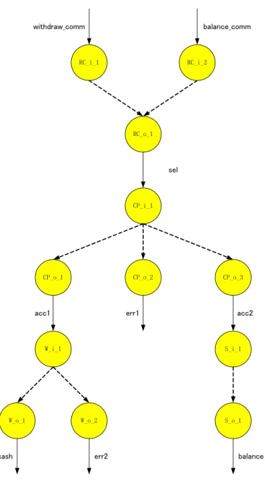
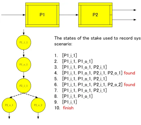
The animation method adopted in our inspection approach is calledsystem functional scenario-based animation method [76]. Comparing to other existing animation methods, this method does not need the translation from formal speci…cation languages to programming languages. The operational behaviors in our animation method are presented as system functional scenarios (orsystem scenariosfor short) rather than the execution paths. A system scenario in SOFL formal speci…cation can be formally de…ned as a sequence of processes or graphically presented as a data ‡ow path in the CDFD. To dynamically demonstrate an operational behavior, every process involved in a system scenario is demonstrated in turn to the inspector. Such step-by-step style can guide the inspector read through the formal speci…cation in a systematic way. The animation performed on the CDFD also provides inspector with an intuitive way for understanding how each part of the formal speci…cation works together. See Chapter 4 for details.
The checklist in our inspection approach is built on the basis of the traceability of speci…cations [77] [78]. The traceability can be either internal or external. By internal traceability, we mean the traceability exists within the same level speci…cation. For example, the internal traceability of informal speci…cation describes the relations between di¤erent items de…ned in the informal speci…cation. In contrast with internal traceability, the external traceability is the traceability between the speci…cations belonging to di¤erent levels. For instance, the traceability
between informal and formal speci…cations is external traceability. It represents the relations between the informal speci…cation items and formal speci…cation items. In order to avoid unnecessary ambiguity, the term traceability used in the rest of this dissertation refers to the external traceability.
The traceability is utilized for building checklist because of: 1) using the informal speci…cation as a representative of user’s requirements to help the inspector to validate the formal speci…cation; 2) using the informal speci…cation as a reference to help the inspector to verify the formal speci…cation. The questions on the checklist are designed to examine the formal speci…cation from four aspects: necessity, appropriateness, correctness, and completeness.
These questions guide the inspector to check the correctness of the formal speci…cation and the consistency between the informal and formal speci…cations. See Chapter 6 for details.
Unlike the conventional inspection, the reading process and checklist are formally de…ned in our inspection approach. Therefore, using a tool to automatically support the inspection process becomes possible. Along with the proposed inspection approach, we provide a prototype software tool to support the entire process of speci…cations construction [79], animation [80], and inspection. In addition, this tool also provides a ‡exible framework to integrate other techniques through a set of well de…ned interfaces. Some works of other researchers have already been integrated into it.
The major contributions we make in this dissertation are summarized as follows:
1. SFSBAM to support reading in speci…cation inspection
A system functional scenario-based animation method (SFSBAM) is proposed and elaborated. By this method, all of the possible system functional scenarios are …rst automatically derived from a CDFD and animation for each of the derived system scenario is then carried out as a reading technique to aid a thorough inspection of its consistency and validity. A system functional scenario is a data ‡ow path in the CDFD that de…nes an independent relationship between the input and output of the CDFD through the formal speci…cations of the processes involved in the path, see details in Chapter 3.1.1 and Chapter 4.
2. Traceability-based checklist to support speci…cation inspection
A set of traceability rules between inspection targets and requirement items are formally de…ned. The de…nition of traceability rules include the formal de…nition of user’s requirements in the informal speci…cation
and the formal de…nition of inspection targets in the formal speci…cation. Based on the formally de…ned traceability rules, a traceability-based checklist is proposed. The questions on the checklist are designed to check the formal speci…cation from four aspects. Several properties are proposed to restrict the contents of formal speci…cation and its relation with informal speci…cation. Moreover, a dependence chain are proposed to guide the inspector check all related inspection targets. See details in Chapter 5 and 6.
3. A prototype tool to support speci…cations construction and inspection
A prototype software tool is developed to support both the construction of formal speci…cations and the inspection of speci…cations. The major interesting functionality of the tool includes supporting the construction of both CDFDs and modules, automatically maintaining the structural consistency between the CDFD and the module, decomposing high level processes, automatically deriving all possible system functional scenarios from a designated CDFD, carrying out animation as a reading technique to support the inspection of the consistency and validity of each system scenario, and managing all of the related data …les.
See details in Chapter 7.
4. An experiment to evaluate the performance of our inspection approach
An experiment is conducted to evaluate the performance of our proposed inspection method. In the experi- ment, the subjects are divided into di¤erent groups based on their experience in SOFL formal speci…cations.
All the groups are required to inspect the same formal speci…cation but use di¤erent inspection methods.
We compare our inspection method with the traditional checklist-based inspection method, and the results indicate that our inspection method is more e¤ective to help the inspector to detect defects contained in the formal speci…cation. We analyze the reasons that lead to the results and point out our …ndings. See details in Chapter 8.
Note that the principles of the proposed approach in this dissertation are not only applicable to the SOFL speci…cation language, but also to other model-based formal speci…cation languages, such as the well known VDM- SL and B-Method because they use similar formal notations and mechanism for constructing formal speci…cations.
We choose SOFL as the target formal technique for discussion in this dissertation partly because it has been recognized as a practical technique by academics and practitioners [47] [81] [82] [83] and partly because it shares
many commonalities with existing model-based formal notations as mentioned previously. Thus, the proposed approach can be easily learned and applied by academics and practitioners even with the background of other existing formal methods.
1.4 Summary
In this Chapter, we …rst discussed why requirements speci…cation is so important to ensuring the quality of the software product. We also discussed the major challenges of informal speci…cation veri…cation and validation, and then brie‡y introduced formal methods and formal engineering methods, and discussed some well studied formal speci…cation veri…cation and validation techniques. Finally, we proposed a novel inspection approach based on speci…cation animation and speci…cations traceability.
In the next Chapter, we will introduce the structure of SOFL informal and formal speci…cations which will be used to demonstrate our inspection approach.
Chapter 2
Brief Introduction of Structured Object- oriented Formal Language
In our inspection method, the formal speci…cation is veri…ed and validated against the informal speci…cation based on the traceability between the two speci…cations. The construction of traceability between speci…cations is critically a¤ected by the structure of the speci…cations. In this chapter, we brie‡y introduce the fundamental principle of the SOFL formal engineering methods and the structure of SOFL informal and formal speci…cations, which will be used as target speci…cations in our approach. For more details of the SOFL, the reader can refer to theSOFLbook [36] and other related work [81] [82] [83] [84] [85].
SOFL stands for Structured Object-oriented Formal Language and was …rst proposed in Liu’s paper [86]. It is not only a formal language, but also a software modelling approach. It is designed to bridge the formal methods and their applications in real software development. Comparing to other formal methods, the SOFL formal engineering method provides both a comprehensible formal language and a practical three-step method for constructing formal speci…cations.
As a formal engineering method, SOFL provides rigorous but practical techniques to build formal speci…cation of software system in a three-step evolutionary manner. In this three-step modelling approach, three kinds of speci…cations with di¤erent level of formalization are constructed, namely the informal, semi-formal, andformal speci…cations.
The informal speci…cation is …rst constructed in a development process. The major task of building informal speci…cation is to discover and collect all desired requirements from the end user. Informal speci…cations can
generally be speci…ed in any style as long as it can be used to communicate with the user easily. In SOFL modeling approach, it is speci…ed in a structured natural language containingfunctions,data resources, andconstraints
The semi-formal speci…cation is re…ned from the informal speci…cation. It is a more accurate and better structured speci…cation to enhance communications between the user and the designer and to help the designer clarify ambiguities in the informal speci…cation. All the requirements in the informal speci…cations are encapsulated into system modules in the semi-formal speci…cation. The desired functions in each system module are de…ned as SOFL processes. In the semi-formal speci…cation, not everything is fully formalized. The data structures and interface of processes are formally de…ned, but the functionality of each process is informally de…ned using structured natural languages. Since the semi-formal speci…cation is used to communicate with the end user to clarify the software system, de…ning the functionality of the system using informal language is reasonable. The formally de…ned data structures and informally de…ned functionality are adopted as basis to construct formal speci…cation.
Theformal speci…cation re…nes the semi-formal speci…cation according to the feedbacks from the end user and formalizes the informal parts of the semi-formal speci…cation. The expected function of each SOFL process is formally de…ned by mathematically-based notations in a manner of pre- and post-conditions. It is intended to precisely and accurately de…ne the functionality and architecture of the software system.
Since the traceability used in our inspection method is constructed between SOFL informal and formal speci…- cations, we introduce the structure of these two kinds of speci…cations as follows.
2.1 Informal Specification
As shown in Figure 2.1, three sections of requirements must be documented in the informal speci…cation. The
…rst section, “Functions”, is a collection of desired functions. Each function describes an expected behavior to be implemented in the system under development. A function can be decomposed into several low level functions and all functions are presented hierarchically. Each function in the informal speci…cation is assigned with an unique identi…er which consists of a capital character “F” and the number in front of the function. For example, the
…rst function in the informal speci…cation shown in Figure 2.1 is “Withdraw”, and its identi…er is “F1.1”. We will use this identi…er to indicate the function “Withdraw” in the rest of this dissertation. The identi…ers of other
requirement items in the informal speci…cation have the same structure.
Another section in the informal speci…cation is the “Data Resources”, which works like database to supply necessary data to the functions listed in the “Functions” section. The data items listed under “Data Resource”
can be accessed or updated by more than one function. The identi…ers of the functions that have the potential to access a speci…c data resource are listed in a pair of brackets after the description of the data resource. For instance, the only data resourceD2.1 will be accessed or updated by functionF1.1.2,F1.1.4,F1.2.2, and F1.2.3 as shown in Figure 2.1.
The third section of informal speci…cation is “Constraints”. It describes a collection of constraints either on the captured functions or the data resources. A constraint shows a restriction condition that usually prevents the system from providing unnecessary functions; it can be used to document nonfunctional requirements, such as business policy, safety, or security. The identi…ers of the functions or data resources that have to comply with a speci…c constraint are listed after the description of the constraint. For example, the functionF1.1.3 is listed after constraintC3.4, that means the functionality described inF1.1.3 must comply with the C3.4. Namely, the
“Receive withdraw amount” function should not accept a withdraw amount that is lager than 10,000.
2.2 Formal Specification
A SOFL formal speci…cation consists of a hierarchy of CDFDs and the associated hierarchy ofmodules. Each module in a SOFL speci…cation is a structure, which contains necessary constant declarations, type declarations, state variable declarations,invariant de…nitions, and a collection ofprocessspeci…cations. For example, one module named “SYSTEM_ATM”is shown in Figure 2.2 and its associated CDFD is displayed in Figure 2.3. This module contains one type declaration, one state variable, three invariants, and four processes.
Theoretically, each desired function in the informal speci…cation is realized by aprocess speci…cation; each data resource is represented by astate variable with a correspondingtype declaration; and each constraint is mapped to either part of aprocess speci…cation or to aninvariant, which is a property that must be sustained by all related processes throughout the entire speci…cation. Eachprocess in a module of SOFL formal speci…cation presents an independent operation that produces output data based on the input data it receives. It can access and update the data of state variables de…ned in the same module, which usually realize the data resources described in the
1 Functions
1.1 Withdraw
1.1.1 Receive command 1.1.2 Check password
1.1.3 Receive withdraw amount 1.1.4 Pay cash
1.2 Check balance
1.2.1 Receive command 1.2.2 Check password 1.2.3 Show balance
2 Data Resources
2.1 Bank account database (F1.1.2, F1.1.4, F1.2.2, F1.2.3)
3 Constraints
3.1 Only two commands can be received “withdraw” and
“showbalance”(F1.1.1, F1.2.1)
3.2 ID No. of each account should be 4 digital number (F1.1.2, F1.2.2, D2.1)
3.3 Password of each account should be 4 digital number (F1.1.2, F1.2.2, D2.1)
3.4 Maximum amount of withdraw is 10,000 (F1.1.3)
Figure 2.1: The informal speci…cation of a simpli…ed ATM software
informal speci…cation.
For each module, there is a corresponding formal graphical notation called Condition Data Flow Diagram (CDFD). The CDFD uses visual notation to intuitively and comprehensibly express the structure of a module, namely the relationships between di¤erentprocesses contained in the module. A process in a CDFD is represented by a rectangle box with its name in the center. Di¤erent processes are connected by data ‡ows to present the potential functions of a formal module. In addition to the data ‡ows, a process can access to the data in a data store. A data store is the graphical representation of a state variable declared in the associate module. The relation between a process and a data store in a CDFD is consistent with the relation between the process and the corresponding state variable in the associated module.
The CDFD is both a formal and intuitive notation suitable for describing system structure. Figure 2.3 shows the associated CDFD of the module displayed in Figure 2.2, four processes “Receive_Command”, “Check_Password”,
“Withdraw”, “Show_Balance”, and a data store “Account_…le” are included.
As shown in Figure 2.2, a process in SOFL formal speci…cation consists of …ve parts: name,input variable list,
module SYSTEM_ATM;
type
Account = composed of id: string
name: string password: string balance: real
available_amount: real end;
var
ext #Account_file: set of Account;
inv
forall[a: Account] | len(a.id) = 4;
forall[a: Account] | len(a.password) = 4;
forall[a, b: Account] | a <> b a.id <> b.id;
process Receive_Command(withdraw_comm: string | balance_comm: string) sel: bool pre true
post withdraw_comm = “withdraw” and sel = true or
balance_comm = “balance” and sel = false end_process;
process Check_Password(id: string, sel: bool, pass: string) acc1: Account | err1: string | acc2: Account ext rd #Account_file
pre true
post (exists![x: Account_file] | ((x.id = id and x.password = pass) and (sel = true and acc1 = x or sel = false and acc2 = x)))
or
not(exists![x: Account_file] | (x.id = id and x.password = pass)) and err1 = "Reenter your password or insert the correct card"
end_process
process Withdraw(amount: nat0, acc1: Account) cash: nat0 | err2: string pre...
post...
end_process
process Show_Balance(acc2: Account) balance: nat0 pre...
post...
end_process end_module
Figure 2.2: The formal speci…cation of module “SYSTEM_ATM”
Receive_command Check_Password
Withdraw
Show_Balance balance_comm
withdraw_comm
sel id
pass
err1 acc1
acc2
amount cash
err2
balance Account_file
Figure 2.3: The CDFD of a simpli…ed ATM software
output variable list, pre-condition and post-condition. The name of a process is an identi…er. The input variable declarations are put in parenthesis. In some process, the input variable list is divided by vertical bars into several input ports. Each input port contains some input variables and is exclusive to each other. For example, the process
“Receive_Command”in Figure 2.2 contains two input variables “withdraw_comm”and “balance_comm”. These two input variables being separated by a vertical bar indicates that the process “Receive_Command” cannot receive them in the same time. The process can receive either input variable “withdraw_comm” or input variable
“balance_comm”. The input variable list is followed by the output variable list. It is de…ned in the same manner as input variable list. The vertical bars can divide the output variable list intooutput ports.
The pre- and post-conditions formally de…ne the semantics of the process using mathematically-based notations.
The semantics of a process is interpreted as follows: when one of the input ports of the process is activited, which means that the values of the input variables included in the activited port satisfy the pre-condition, the process will be executed. As a result of the execution, one of the output ports is made avaliable, which means that the values of its output variables satisfying the post-condition are produced based on the input values.
In the CDFD, the input and output ports of a process is denoted by the narrow rectangles on the left and right side of a process, respectively. They are used to receive and send out input and outputdata ‡ows, which are the
counterparts of input and output variables in the CDFD. When one of the input ports of a process receives all the necessary input data ‡ows, the process can be activated and executed to produce corresponding output data ‡ows.
In the SOFL formal speci…cation, the processes contained in the same module can contact with each other via input and output variables. A process can also be decomposed into a lower level module, which contains a group of lower level processes. This decomposition can be continued until the designer considers that the process no longer needs to be decomposed. Generally, the type declarations, state variable declarations, and invariant de…nitions are used inside the module that de…nes them. But, if a process is decomposed into a new lower level module, the types, state variables, and invariants speci…ed in the module containing the process can be used directly in the new lower level module.
2.3 Summary
In this Chapter, we brie‡y introduced the structure of SOFL informal and formal speci…cations. In the next Chapter, we will give an overview of our inspection approach, and the background of the example used in this dissertation will also be introduced.