power systems
Author(s)
Yamashita, Katsumi; Miyagi, Hayao
Citation
琉球大学工学部紀要(35): 69-78
Issue Date
1988-03
URL
http://hdl.handle.net/20.500.12000/5572
Bull. Faculty of Engineering, Univ. of the Ryukyus, No 35, 1988 69
Decentralised LQI-Type Load-frequency control with controlling
delay of one sampling time for interconnected Power systems
Katsumi YAMASHITA* and Hayao MlYAGI*
Abstract
This paper presents a new method of designing decentralised discrete-type load-frequency regulator with controlling delay of one sam pling time for interconnected power systems. In this method, the intercon nected multi-area electric energy system is decomposed into several subsystems, each of which is controlled separately by using a local feed back only. An especially attractive feature of the proposed control
scheme is that it considers the time delay due to the computation time of
the control law and the transmission time of the system data over the
telemeter links to the controlling plant. An additional feature is that the
construction of the regulator is based on the conventional tie-line bias control. The proposed control scheme is illustrated by digital simulation of a 2-area system provided with reheat steam turbines. The results show that this discrete-type regulator can act satisfactorily for improving dynamic responses of the load-frequency control.
1. Introduction
The load-frequency control (LFC) problem has been one of the major subjects concerning power-system engineers, and the objective of LFC is to minimize the transient errors in the frequency and the scheduled tie-line power and ensure zero steady-state errors of these two quantities1"3. For many years, a considerable research effort has been devoted to the development of control strategies for the LFC problem using continuous-time optimization techniques3"6.
However, further consideration may be required for practical implementation of control strategies designed by using continuous-time optimization techniques, because, in practical power systems, the system data (frequency, tie-line power etc.) are available in the discrete form, i.e. the system data are first sampled and then transferred over telemeter links. Also the use of digital computers has become practically indispensable to electric energy systems, because, with the use of digital computers, it is now possible, through suitable software, to realise a wide range of control strategies. Accordingly, it may be necessary to construct discrete-type regulators for such practical situations. However, until now, few works7"9 have been done concerning discrete-time load-frequency control, and in most of the past works, they have ignored the time delay due to the computational time of the control law and the transmission time of the system data over the telemeter links to the controlling plant.
Received: Octover 31, 1987.
Furthermore, it is recognized that the implementation of a centralised load-frequency control possesses certain difficulties, when the size and complexity of the interconnected power systems increses. Specifically, these difficulties can be traced to the need for elaborate instrumentation and telemetery of the required data to the central controller. Also the computational requirements grow very fast with the number of interconnected
areas. In recent years, significant efforts have been made to establish suitable
decentralised regulator for large interconnected power systems10"11.
This paper presents a new method of designing decentralised discrete-type load-frequency regulator with controlling delay of one sampling time for interconnected power systems. In this method, the interconnected multi-area electric energy system is decomposed into several subsystems, each of which is controlled separately by using a local feedback only. An especially attractive feature of the proposed control scheme is that it considers the time delay due to the computation time of the control law and the transmission time of the system data over the telemeter links to the controlling plant. An additional feature is that the construction of the regulator is based on the conventional tie-line bias control, which is used by most utilities of the present day.
In this paper, we apply the newly designed regulator to 2-area power system provided with reheat steam turbines. The results show that the proposed discrete-type regulator can act satisfactorily for improving dynamic responses of the load-frequency control.
2. Notation
f* = nominal system frequency i = subscript referring to area i A f, = incremental frequency deviation
A Ptl = incremental generation change
A Prl = incremental generation change during steam reheat A Pgi = incremental change in governor valve position A PUei = incremental change in tie-line power
A PC| = incremental change in speed changer position A Pd, = incremental load demand change
H) = inertia constant
Di =load frequency constant
kh, =high pressure turbine power fraction Tn = reheat time constant
Tij = synchronising coefficient Tu = steam chest time constant Tg, = speed governor time constant
Ri =self regulation parameter for the governor /?i = frequency bias parameter
Ts = sampling period
A = small deviation of state variable s = Laplace operator
Bull. Faculty of Engineering, Univ. of the Ryukyus, No 35, 1988 71
{Other symbols are defined in the text.)
3. Problem formulation
A typical 2-area power system with reheat steam turbines is shown in Figure 1 for LFC. In state variable form, the continuous-time dynamics of the i-th controlling plant in an n-interconnected system is described by a set of linear differential equations with input delays: 1 Ri APei. Steam turbine Governor ! + w l+sTfl,1 1 l+sTti APf| l+sKhiTri l+3Tr, L Steam turbine Governor ] APc?
T
I
1 «2 1 l+sTfl2 AP02| 1 l+sTt2 I l+sKh2Tr2 l+STr2 APd 1 flPt 1. I + J | Apt2 S k AP + APd: Area 1 1 t le Ti2 s Area 2 1 2H|a4D2 t Af| + U Af2Fig. 1 Block diagram of 2-area reheat thermal system
J,(t) = A,x,(t)+ 2 A,Jxj(t)+B,u,(t-Ta)+r,v,(t)
where
(1)
*,= [A f, A Ptl A Prl A Pgl A PtIe1]T u,= [A Pcl] v,= [A Pdl]
and Ts is the sampling period. In this case, Ui(t —Ts) with controlling delay of one sampling time is sufficient to consider the effect of the time delay due to the computation time of the control law and the transmission time of the system data over the telemeter links to the controlling plant for practical sampling periods (1.5 ^Ts^ 2.5) used for LFC.
A,= A,.= f*D, 2H, 0 0 1 TglRi 2TU 0 0 0 0 A IJ f* 2H, 1 Trl 0 0 0 0 0 0 0 0 0 1 kij_ Trt TM L_ T« 0 0 0 khi T« 1 Tt, 1 T., 0 f 2H, 0 0 0 0 B,= 0 0 0 1 Tgl 0 (2) r = 2H, 0 0 0 0
However, if it is assumed that V|(t) represents known disturbances, equation (1) can be
rewritten in the standard state form as
x,(t) = A,x,(t)+B,u,(t-T8) *.(0)= -*.a (3)
where Xi and U| are the new state and control vectors which equal the old vectors minus these steady state values X|S and uis. In equation (3), the coupling terms between the areas are set equal to zero to simplify the problem formulation (non-zero coupling is considered in the example).
Since the control signals Ui(t), (i = l, 2, , n) are now outputs of sample-and-hold devices, they are constant during the sampling period Ts and described by
u,(k-lTB) for (4)
Thus the solution of equation (3) is found to be
e Al(t"r)
x,(t)=e A|(t~kTs)jcf(kTs)+ f e Al(t"r) B,dni,<k=lT.)
J kTsA(tkT)+ [eA,(t-kTJ_I-, A (5)
The equation can be further modified to describe the transition of the states of the digital system at the sampling instants only. By letting t = k-f-lTs, equation (5) becomes
(6) where
Bull. Faculty of Engineering. Univ. of the Ryukyus, No 35, 1988 73
I = identity matrix
Since the steady-state errors of frequency and tie-line power deviations should be driven to zero by LFC, we suggest as feedback signals accumulative quantities of the area control error on the basis of linear quadratic integrating technique12. They can be defined as follows:
\= 2 <#Afl(m)+APllcl(m)}
m=o
Using equation (6), equation (7) can be rewritten as
B)=Jf,(kT9)+C,x,(
(7)
(8) where
C,= [ft 0 0 0 1]
Now, define the augumented state vector as
*,(k)T = [x,(k)T x,(k) (9)
where x,(k), Jt,(k) and Ui(k-l) imply X|(kTs), jc,(kTs) and Ui(k —1TS), respectively.
The augumented set of difference equations for LFC system are
where *, C,G, 0 0 1 0 c ^ 0 *,= 0 0 1
An optimal control can be achived by minimizing a quadratic cost function of the form
J, = E[5 ^l(k)TQ,j,(k) + u,(k)TR,ul(k)}]
(ID
k0
subject to the system control constraint of equation (10), where E is the expectation operator over the random initial state, Qi is 7X7 symmetric positive-semi-definite con
stant matrix and Ri is positive scalar value. Now, define the output vector y,(k) as
y,(k)= [Af,(k) APMe,(k)]T
02)
These variables are easily measurable variables and used as the feedback signals of the conventional tie-line bias control. Additional, Xi(k) constructed by the elements of equation (12) and Ui(k —1) are measurable variables. Therefore, suppose that control
variable Ui(k) is represented by a linear combination of measurable variables yi(k), and ut(k —1) as follows:
u,(k)=-F,C,xl(k)
0
where FT = F F F u 12 13 D,= 10 0 0 0 0 0 0 0 16,=
D, 0 0 0 1 0 0 0 1and Fj is undefined feedback gain vector.
Substituting for Ui(k) from equation (13) in equation (10), the closed-loop system matrix
becomes ri=<$,— ^FifK.equation (10) reduces to
=rlx,(k) 04)
and the performance index J, is also expressed as
J,=E K,(0)TP,x,(0)]
05)
where P, is the solution of the Lyapunov Matrix equation
p,-rTP.r,=QI+GTFTRiF,Dl
06)
On assuming now that jc,(O) is uniformly distributed over the surface of a hypersphere13,
the performance index becomes
Ji=trP,
07)
where trPj is the sum of the diagonal terms of P,.
Therefore F, for the optimal controller must be determined in such a manner that J, can be minimized subject to the constraint given by equation 06). For minimizing J(, the Hamiltonian
,(Q,+5T ft R.FtC-fri p.r.-p,)
is chosen and the necessary conditions for minimization of H( I n 3Hi
(18)
8Fr°'
3L,~W'
3P,
yield the following solutions: F, = (R,
Bull. Faculty of Engineering, Univ. of the Ryukyus, No 35, 1988 75
The equations (20),{2D and (22) are solved iteratively in the following steps:
Step 1: Assume an initial value of Ftt>i such that all eigenvalues of ($) —¥iF|f)i) lie inside
of the unite circle in the z-plane.
Step 2: Use this value of F|fit to solve equations (21) and (22) for P, and L,.
Step 3: Find a new value of Fi by substituting these values of Pi and L| in equation (20).
Step 4: Obtain a new value of F|6, by using the value of Fi from Step 3, and then return
to Step 2.
By executing the above steps, we can uniquely determine the optimal feedback gain
vector Ff. 4. Application
A 2-area power system with reheat steam turbines as shown in Figure 1 is used to evaluate the effectiveness of the proposed load-frequency controller. The values of the
system parameters are given in Table 1. The weighting matrices in equation (11) are shown
as Qi =1 and Ri = l, (i=l, 2), respectively. The optimal feedback gain vectors Fi,(i=l, 2) are
obtained as the solution of equations (20),(2D and (22). The results are indicated in Table 2 (A
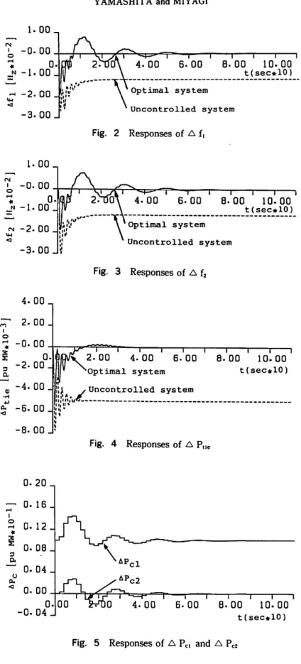
ACEi(m) implies fix A f,(m) +A Ptlel(m)). Figures 2-5 indicate the control effects achived by the proposed load-frequency regulators under a step-load change A Pdl = 0.01 pu MW in area 1. Curves in Figures 2-5 show the performance of A flfA f2,A Ptle and A Pc for the optimal system and the uncontrolled system (here set A ptle = A ptlel = -APtie2). The solid curves show the performance of the optimal system, whereas the dotted curves show the performance of the uncontrolled system. It can be seen from these figures that the transient errors in the frequency and the scheduled tie-line power are much reduced and zero steady-state errors of these quantities are ensured, by the regulator with the optimal
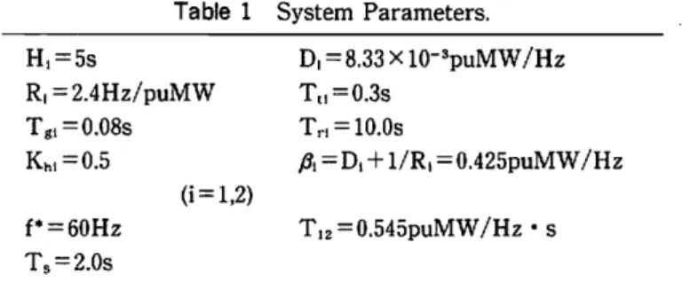
Table 1 System Parameters. H, = 5s R, = 2.4Hz/puMW Tgi= 0.08s Khi=0.5 f* = 60Hz T, = 2.0s D, = 8.33X10⁻³puMW/Hz Tt,=0.3s Trl = 10.0s /?,=D, + l/R1 = 0.425puMW/Hz T12 = 0.545puMW/Hz-s Table 2 Ourput feedback Af,(k) APt,e,(k)
£ A ACE^m)
m-o APcl(k-l)Optimal feedback gain vector
F, -0.1776 0.3594 0.5320 0.1052 Output feedback A fa(k) A PtIe,(k)
£ A ACE2(m)
m=o AP«(k-l) F, F2 -0.1776 0.3594 0.5320 0.10521.00,
2Vtf6V 4^00 ' 6.'00
8.00
10-00
\ t(sec*10) \ Optimal system Uncontrolled system Fig. 2 Responses of A f, 1.00., -0-00. o. -1.00--2.00. -3.00. ^_e.m *-~* i '—i 1 1 1 1 \2.n00\
4-00
6.00
8.00
10-00
t(sec*10) Optimal system Uncontrolled system Fig. 3 Responses of A f2 2.00 ~H4.00 1 6-001 1 8.001 1 10.001 t(sec*10) -8-00 Optimal system Uncontrolled systemFig. 4 Responses of A P,le
0-20
zr
°-16-iS 0-12.
* 0-08.
a 0-04. o EU 0. DO 0. -0.04.00 c2 4.00 6.00 8.00 10-00 t(sec*10)Bull. Faculty of Engineering, Univ. of the Ryukyus, No 35, 1988 77
gains. It may thus inferred that the proposed control scheme can be acceptable for LFC of interconnected power systems.
5. Conclusions
In this paper, a new method of. designing a decentralised discrete-type load-frequency regulator with controlling delay of one sampling time has been proposed, and the effective ness of the proposed regulator has been shown in 2-area power system with reheat steam
turbines. The major contributions of this paper are as follows:
(a) The proposed control scheme is very realistic, because the regulator is designed to
consider the effect of the time delay due to the computation time of the control law and the transmission time of the system data over the telemeter links to the controlling plant.
(b) The realisation of this regulator is very easy, because the feedback data, required to form the control signals are only sampled frequency and tie-line power, which are used by most of the utilities of the present day.
6. Acknowledgement
The authors wish to thank Dr. T. Taniguchi, University of Osaka Prefecture, for his valuable advice. The authors are favored to have had the assistance of R. Imabeppu, S. Ikemura and K. Oyadomari, who contributed their experimental skill and sustained effort in the execution of the experiment. This work was supported by the Grant in Aid for Scientific Research from the Ministry of Education of Japan.
7. References
[ 1 ] Elgerd, O.I., Fosha, C.E., "Optimum Megawatt-Frequency Control of Multiarea
Electric Energy Systems", IEEE Transactions on PAS-89, 1970, pp.556-562.
[ 2 ] Elgerd, O.I., Electric Energy Systems Theory: An Introduction, McGraw-Hill
INTERNATIONAL, 1983.
[3] Fosha, C.E., Elgerd, O.I., "The Megawatt-Frequency Control Problem: A New
Approach Via Optimal Control Theory", IEEE Transactions on PAS-89,1970, pp.563
-577.
[ 4 ] Nanda, J., Kaul, B.L., "Automatic Generation Control of an Interconnected Power
System", Proc. IEE, vol.125, 1978, pp.385-390.
[5] Hsu, Y.Y., Chan, W.C., "Optimal Variable Structure Controller for the
Load-Frequency Control of Interconnected Hydrothermal Power Systems", Int. J. of
Electrical Power & Energy Systems, 1984, pp.221-229.
[ 6 ] Yamashita, K., Taniguchi, T., "Optimal Observer Design for Load-Frequency Con
trol", Int. J. of Electrical Power & Energy Systems, 1986, pp.93-100.
[ 7 ] Bohn, E.V., Miniesy, S.M., "Optimum Load-Frequency Sampled-Data Control with
Randomly Varying System Disturbances", IEEE Transactions on PAS-91, 1972, pp. 1916-1923.
[ 8 ] Glover, J.D., Schweppe, F.C., "Advanced Load Frequency Control", IEEE Transac tions on PAS-91, 1972, pp.2095-2103.
[9] Tripathy, S.C., Bhatti, T.S., Jha. C.S., Malik, O.P., Hope, G.S., "Sampled Data
Automatic Generation Control Analysis with Reheat Steam Turbines and Governor Dead-Band Effects", IEEE Transactions on PAS-103, 1984, pp.1045-1051.
[10] Hiyama, T., "Design of Decentralised Load-Frequency Regulators for Interconnected
Power Systems", Proc. IEE, vol.129, 1982, pp.17-23.
[11] Geromal, J.C., Peres, P.L.D., "Decentralised Load-Frequency Control", Proc. IEE,
vol.132, 1985, pp.225-229.
[12] Narita, S., Digital Control Systems: Theory and Application, Syoukoudo, 1980.
[13] Levine, W.S., Athans, M., "On the Determination of the Optimal Constant Output
Feedback Gains for Linear Multivariable Systems", IEEE Transactions on AC-15,