PAPER
Special Section on Smart Multimedia & Communication SystemsFrequency E ffi cient Subcarrier Spacing in Multicarrier Backscatter Sensors System
Jin MITSUGI†a), Yuki SATO†, Yuusuke KAWAKITA††,andHaruhisa ICHIKAWA†††,Members
SUMMARY Backscatter wireless communications offer advantages such as batteryless operations, small form factor, and radio regulatory ex- emption sensors. The major challenge ahead of backscatter wireless com- munications is synchronized multicarrier data collection, which can be re- alized by rejecting mutual harmonics among backscatters. This paper ana- lyzes the mutual interferences of digitally modulated multicarrier backscat- ter to find interferences from higher frequency subcarriers to lower fre- quency subcarriers, which do not take place in analog modulated multicar- rier backscatters, is harmful for densely populated subcarriers. This reverse interference distorts the harmonics replica, deteriorating the performance of the existing method, which rejects mutual interference among subcar- riers by 5 dB processing gain. To solve this problem, this paper analyzes the relationship between subcarrier spacing and reverse interference, and reveals that an alternate channel spacing, with channel separation twice the bandwidth of a subcarrier, can provide reasonably dense subcarrier allo- cation and can alleviate reverse interference. The idea is examined with prototype sensors in a wired experiment and in an indoor propagation ex- periment. The results reveal that with alternate channel spacing, the reverse interference practically becomes negligible, and the existing interference rejection method achieves the original processing gain of 5 dB with one hundredth packet error rate reduction.
key words: backscatter communications, interference rejection, software defined radio, harmonics
1. Introduction
1.1 Background
Wireless sensors are expected to lower the installation cost, and to increase the sensor density of automated structural health monitoring (SHM)[1],[2]. The apparent problem of battery-powered wireless sensors is the necessity to re- place the power source (battery) from time to time. Replace- ments of battery incur human interventions, which are major sources of errors, and prevent sensors from being implanted into artifacts. To counter this problem, batteryless wireless sensors are of immense research interests [3]. However, even a batteryless sensor needs to harvest power to estab- lish a two-way communication link.
Backscatter communications[4],[5], which is exten- sively used in RFID, can achieve batteryless sensing and establish a two-way communication link. In a backscatter
Manuscript received February 14, 2019.
Manuscript revised June 11, 2019.
†The authors are with Keio University, Fujisawa-shi, 252-0882 Japan.
††The author is with Kanagawa Institute of Technology, Atsugi- shi, 243-0292 Japan.
†††The author is with The University of Electro-Communications, Chofu-shi, 182-8585 Japan.
a) E-mail: [email protected]
DOI: 10.1587/transfun.E102.A.1834
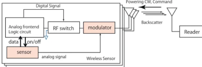
Fig. 1 Backscatter wireless sensor can send sensing signal by changing the antenna impedance.
communication system, a dedicated reader generates pow- ering radio wave and transmits it to a group of wireless sen- sors. The principle of a backscatter communications sys- tem is illustrated in Fig. 1. The powering wave is either modulated to provide commands from the reader to the sen- sors (hereinafter forward link) or continuous wave (CW), which supplies power to the sensors. The return link (sen- sor to reader) can be produced by changing the impedance of the wireless sensor antenna – typically the matched state and the short circuit (total reflection) – with an embedded RF switch. An analog modulated backscatter can be pro- duced by embedding an analog modulator in the sensor, with which the sensor data modulates CW[6],[7].[6]used elec- tret condensor microphone (ECM) and a junction gate field- effect transistor (JFET) to produce amplitude-modulated backscatter.[7]used a commercial phase shifter (Skyworks PS088-315) to produce phase-modulated backscatter. Sen- sor data can alternatively be acquired by the logic circuit with an AD converter or a digital interface, such as serial peripheral interface (SPI), and by digitally modulating CW.
When digital modulation is employed, the modulator block in Fig. 1 is not needed.
A backscatter communications system can eliminate the need for batteries, power amplifiers and synthesizers in sensors, which reduce the complexity of sensor, resulting in the low cost and small form factor, typically an LSI size.
Backscatter communication sensors are exempt from radio regulations, and can be flexibly used across countries by us- ing a reader that conforms to regulations.
To separate the inherently weak return link from the phase noise of the powering or neighbor forward link, a con- stant rate RF switching at the sensor is applied to the base- band signal to shift the backscatter signal away from the CW in frequency domain. This is referred to as a subcarrier[8]
and is extensively used in industrial RFID deployment ow- ing to its robustness against the interferences from neighbor Copyright c2019 The Institute of Electronics, Information and Communication Engineers
systems[9]. Backscatter can be produced by reflecting not only dedicated CW but also ambient radio power[10],[11].
According to Noel [12], when wireless sensors, not restricted to backscatter sensors, are applied to automated SHM, they shall meet the following requirements.
1. Sensor sampling rate ranges from 100 Hz to 1,000 Hz.
2. The number of sensors is up to 70.
3. Sensor data synchronization is below 120µs.
The requirements on the number of sensors and their syn- chronization are important to accurately measure the instan- taneous structural response against an exciting force. There- fore, meeting the two requirements is the primary challenge of wireless sensors for SHM applications, particularly of batteryless wireless sensors. This paper aims to fulfill the re- quirements in a frequency efficient manner by rejecting har- monics among backscatters with artificially produced repli- cas, and by securing appropriate channel separation among backscatters.
1.2 Related Works
Fu et al.[13]present simultaneous imaging and localization with orthogonal spread spectrum codes in the preamble of a backscatter frame. They confirmed the performance of the proposal with two time-synchronized sensors. Such spread spectrum multiple access (SSMA) or code division multiple access (CDMA) approach can be found in other literature such as[14],[15]. However, the approach suffers from the unavoidable near-far problems because of the absence of the transmission power control of the backscatter and the loss of backscatter orthogonality due to the unstable, and thus inevitably unsynchronized, clocks in backscatter sensors.
Hu et al.[16]proposed Laissez-Faire where the enve- lope of multiple backscatters are analyzed and separated at the reader. They successfully separated up to 16 simultane- ous streams in experiments. This method demands clear en- velope of backscatter, which are only available in high car- rier to interference ratio (CIR) environments. In practical propagation environments, however, envelope are usually unclear in low CIR conditions. Because of this waveshape distortion in low CIR environments, Laissez-Faire will work only in high CIR environments.
Simultaneous use of multiple subcarriers was proposed by Vannuci et al.[17]in which the sensor uses a minimum shift keying (MSK) subcarrier to reduce the harmonics, and uses a narrowband signal (low bitrate). The authors of[17], however, did not introduce any interference canceler, be- cause they assumed that the possible communication outage having resulted from the interferences were ignored. Be- cause the low outage rate is attributed to the low density subcarrier allocation (10 bps bandwidth for up to 200 kHz subcarrier), the method suffers from the wide bandwidth re- quirements for a large number of backscatter sensors.
Reduction of the direct current (DC) component with a set of codewords has been extensively studied in the field of storage systems[18]. Disparity, which is the difference
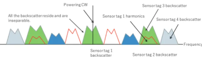
Fig. 2 Pseudo FDMA can be realized by using multiple subcarriers con- currently. But we need to reject unavoidable harmonics.
between the numbers of marks and spaces, can be zero or low while the code rate is nearly equal to one, when us- ing long codewords. However, such a DC-balanced code demands a long state-machine or a large codebook for wire- less sensors. There are interesting studies on perfect pulses [19],[20]to suppress harmonics by enforcing smooth transi- tions with higher clock rates in sensors, in a manner similar to MSK.
1.3 Our Approach and the Problem Statement
In parallel to these existing studies, the authors of this pa- per propose a multiple access method that uses multiple subcarriers concurrently to establish pseudo frequency di- vision multiple access (FDMA) in backscatter communi- cations [21], [22]. The reason we refer to the method as
“pseudo” is because a backscattered subcarrier inevitably generates harmonics. Harmonics interfere with other chan- nels as shown in Fig. 2. By mathematically producing repli- cas of subcarrier harmonics and subtracting them from the observed signal, individual baseband signals that are super- posed onto subcarriers can be extracted. We refer to this method as multiple subcarrier multiple access (MSMA).
The salient feature of MSMA is the harmonics rejection method, referred to as MSMA interference rejection in this paper, which exploits the harmonics characteristics of being generated only in higher subcarrier channels.
While Miller coding, a standard short zero disparity code[8], is used in the evaluations in this work, MSMA in- terference rejection can work with other zero or low dispar- ity codes. We may alternatively avoid the harmonics of sub- carriers interfering with other subcarrriers by placing sub- carriers away from the CW. However, in such placement, the sensor’s clock rate needs to be increased, resulting in larger power consumption. We also need to be careful not to expose the subcarriers to other radio systems that are autho- rized to use the same frequency band.
As introduced in past [7], [22], we confirmed the fundamental principle of MSMA works for analog (phase or frequency) modulated subcarriers. Analog modulated MSMA suffers from unavoidable phase fluctuation caused by, for example, the movement of target artifact or humans in practical environments. This instability confines the use of analog modulated MSMA only in propagation controlled environments such as in an anechoic chamber. Because MSMA rejects harmonics before the demodulation, it also works on digitally modulated subcarriers. In[23], we ap- plied a digital modulation in MSMA to reveal its practical-
ity in an out-door radio propagation environment with four backscatter sensors. During the course of this development, we noticed that the interference rejection method did not work well at times.
As we explain later in this paper, the harmonics of a digitally modulated subcarrier interfere not only with the higher frequency subcarriers but also the lower frequency subcarriers. We refer to this problem as “reverse interfer- ence” in this work. The accommodation of the reverse in- terference into the mathematical formulation of interference rejection is possible, albeit complex. In this paper, the re- verse interference problem is solved by securing sufficient separation between subcarriers, instead of producing the rig- orous harmonic replicas.
The rest of this paper is organized as follows. Although the principle of harmonics rejection in MSMA was proposed in [22], Sect. 2 explains the signal model in backscatter communications tailoring to the digital modulation for com- pleteness. The reverse interference problem associated with digital modulation is also introduced in Sect. 2. This sec- tion clarifies that sufficient subcarrier separation suppresses reverse interference in practice. In Sect. 3, the fundamen- tal performance of interference rejection in a wired and a wireless configuration experiments, where the replicas of harmonics may be distorted by reverse interference, are re- ported. Section 4 concludes the paper.
2. Digitally Modulated Multiple Subcarrier Multiple Access Theory
In this section, we first explain the subcarrier backscatter signal model with digital modulation. The fundamental dif- ference between digitally modulated and analog modulated subcarriers is the infinite bandwidth caused by the phase dis- continuity in a digitally modulated subcarrier. We later show that this problem can be practically solved by securing suf- ficient spacings among subcarriers.
2.1 Subcarrier Backscatter Signal Model
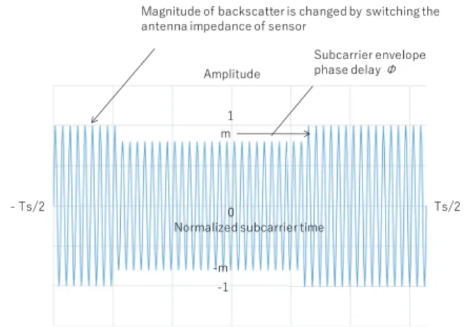
A subcarrier backscatter is produced by a constant rate on/off keying of antenna impedance of a sensor. Figure 3 shows the general backscatter signal at the reader receiver ingress where the time is normalized with the subcarrier pe- riod,Ts, andmdenotes the modulation index. Because the clock timing of a sensor usually differs from that of the cor- responding reader, we introduce a phase delay of subcarrier asφd. The phase delay is combined with the digital phase componentφi depending on the baseband signal encoding, such as Miller and FM0, eitheri = 0 ori = 1, typically φ0 = 0 andφ1 = πare used. The total phase is therefore φ=φd+φi. Because the carrier phase at a sensor depends on the distance between the reader and the sensor, and the modulated phase, the reverted carrier is assumed to have a Ψphase delay at reader. Denoting the carrier angular veloc- ities asωc, the modulated subcarrier signalS(t) at the reader receiver ingress can be written as
Fig. 3 Backscatter subcarrier waveform at the reader receiver. The en- velop is changed by a constant rate toggling of an RF switch.
S(t)=se(t)ej(ωct+Ψ), (1) wherese(t) denotes the square waveform envelope after the attenuation due to propagation.
The frequency components of the square waveform envelope, se(t), can be derived by applying Fourier series based on the subcarrier angular velocity,ωsas follows.
se(t) =m+1+α X
n=1,3,···
1
nsin(nωst−nφ), (2) where
α= 2(1−m) π .
Equation (2) shows that the higher harmonics accompany longer phase delay. This is well-known linear group delay.
It is also shown in Eq. (2) that the harmonics of a subcarrier appear only in odd multiples of the primary subcarrier chan- nel, and the amplitude of higher harmonic decays with the reciprocal ofn.
Substituting Eq. (2) into Eq. (1), the received signal can be rewritten as follows.
S(t) = (m+1)ej(ωct+Ψ) + α X
n=1,3,···
1
nsin(nωst−nφ)ej(ωct+Ψ) (3) The receiver down-converts the incoming subcarrier signal,S(t), by multiplying the carrier signale−jωctand ap- plies a high pass filter (HPF) to achieve the maximum reso- lution of backscatter to yield the baseband signalSb(t) such that
Sb(t) = α X
n=1,3,···
1
nsin(nωst−nφ)ej(ωct+Ψ)e−jωct
= α X
n=1,3,···
1
nsin(nωst−nφ)ejΨ. (4) Because φ comprises the phase delay and the modulation phase such thatφ=φd+φi, Eq. (4) can be rewritten as
Sb(t)=α X
n=1,3,···
1
nsin(nωst−nφd−φi)ejΨ, (5) where the relationship,nφi=φiholds because any odd num- berncan be expressed asn=2m+1 andφi=0 orπ, yield- ingnφi = φi+2mφi = φi. Equation (5) indicates that the same bandwidth appears at every harmonic component.
The IQ components after the down-conversion are ob- tained as follows.
I =α X
n=1,3,···
1
nsin(nωst−nφd−φi) cosΨ Q =α X
n=1,3,···
1
nsin(nωst−nφd−φi) sinΨ (6) In this set of equations,n = 1 represents the primary sub- carrier. Componentsn >1 are the harmonics. Each of the frequency component can be extracted by applying a band pass filter (BPF). Because either I or Q component only comprises a sine wave,Sbproduces a straight line in the IQ plane. This characteristic is known as a zero-cross signal [24].
The phase discontinuity in digital modulation produces infinitesimal harmonics in the modulated signal, which de- cay with frequency separation. A continuous phase fre- quency shift keying (CPFSK), typically MSK can reduce the harmonics, as proposed in[17]. However, in this case, the frequency deviation of the harmonics becomes wider than that of the primary subcarrier because the convenient char- acteristic nφi = φi is no longer valid. The caveat to em- ploying digital modulation in MSMA is, therefore, to avoid any possible adjacent channel interference, particularly the reverse interference, which is not observed in analog modu- lation.
2.2 Digitally Modulated Signal
The raw bit rate of digitally modulated subcarrier – assum- ing that no coding is applied – is determined by dividing the subcarrier frequency by the number of subcarrier cycles ms to represent one bit. The waveform of a single-bit sig- nal for severalms is shown in Fig. 4. Supposing that those waveforms in Fig. 4 represent marks (1 s) then their phase- reversed signals represent spaces (0 s) in BPSK. Note that for all themscases, the bit rates and the required bandwidth remain unchanged because the one-bit duration is constant.
The adjacent channel interference of three subcarriers is calculated as shown in Fig. 5 by applying Fourier series to the waveforms in Fig. 4. It is assumed that any subcarrier has the same power at the receiver. The channel power in Fig. 5 is, therefore, normalized with the peak power. As is seen in Fig. 5, the main interference source to subcarrier 3 is the harmonic of subcarrier 1. The adjacent leakage from channel 2 is about 8 dB less than the harmonic.
Becausems =2 produces the most densely populated subcarriers frequency-wise, the adjacent channel interfer- ence, including reverse interference, is large. The reverse
Fig. 4 Time domain signal of single bit subcarrier.
Fig. 5 Adjacent channel interference among subcarriers in casems=2.
interference on the first subcarrier is particularly severe be- cause the negative frequency components of harmonics of digitally modulated signals are reflected at the carrier fre- quency, and they spill over to the positive frequency domain.
For comparison, the spectrum in the case ofms = 4 is shown in Fig. 6. By comparing Figs. 5 and 6 it is clear that the adjacent channel interference can be mitigated by securing wider subcarrier channel separation.
The aggregated reverse interference on the first subcar- rier from the second and third subcarriers are calculated as in Fig. 7 assuming that after the fourth subcarrier the reverse interference on the first subcarrier is negligibly small. In the case of ms = 4, the CIR of the first subcarrier is ap- proximately 14 dB. The CIR is calculated by dividing the subcarrier 1 channel power (0 dB) by the aggregated reverse interference from subcarriers 2 and 3, which is sufficiently high for BPSK demodulation. With these observations, it is shown that digitally modulated MSMA is feasible when sufficient subcarrier spacing is secured by using more than three subcarrier cycles to represent a bit. However, the in- crease of subcarrier spacing deteriorates frequency effi-
Fig. 6 Adjacent channel interference among subcarriers in casems=4.
Fig. 7 Aggregated adjacent channel interference on the first subcarrier.
ciency. From Fig. 7, a reasonable tradeoff is observed to bems=4, because the improvement in CIR somewhat sat- urates forms>4.
3. Performance Evaluation of Digitally Modulated MSMA
3.1 Prototype System
We developed a prototype MSMA system using USRP 2952R and LabVIEW Communications as the transmitter and the receiver. The host PC on which LabVIEW com- munications runs is equipped with Win7 Core i7, 4.0 GHz clock, with a memory of 64 GB.
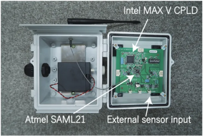
The prototype backscatter sensor uses a CPLD (Intel MAX V) and an MCU (Atmel SAML21) as shown in Fig. 8.
We did not implement a crystal oscillator in the prototype sensor, but used the internally generated clock of the MCU to emulate the low-stability clock of LSI sensor. A clock rate of 4 MHz was used in the experiment. The prototype sensor was housed in a water-proof case for outdoor experiments.
The subcarrier frequencies and subcarrier channel sep- arationmsof the prototype sensor can be changed by using an embedded DIP switch and also by changing the firmware.
The sensor modulates its subcarrier with a predefined pat- tern or a 12 bit A/D converted external analog signal. In
Fig. 8 Prototype backscatter sensor.
Fig. 9 Packet structure of digitally modulated streaming.
either case, 8 bit sequence number, data and 4 bit check sum are Miller encoded, and adding 4 bit equivalent preamble which violates the Miller encoding to facilitate the frame synchronization as shown in Fig. 9. Each sensor continu- ously modulates the subcarrier with the sequence of packets.
3.2 Subcarrier Separation and MSMA Interference Rejec- tion
We use three sensors – sensor 1, sensor 2 and sensor 3 – which are allocated with three consecutive subcarrier chan- nels, fs,2fs,3fswherefsis the unit subcarrier frequency of sensor1. Because of the principle of subcarrier harmonics, sensor 1 always interferes with sensor 3 channel. If there is a harmful reverse interference from sensor 2 on sensor 1, the replica of sensor 1 harmonic in the sensor 3 channel gets distorted. As a result, the performance of MSMA interfer- ence rejection for the sensor 3 channel deteriorates. Those sensors are connected to a USRP2952R with SMA cables and an attenuator to adjust CIR. Because the bit-rate is 10 kbps in any case and any sensor, the channel separations in ms=2,ms=3,ms =4 are equivalent to one, one and half and twice the bandwidth defined in Fig. 4, respectively. We use fs =20 kHz, 30 kHz, 40 kHz, and 50 kHz to represent ms = 2,3,4,5 settings, respectively, as shown in Table 1.
Because the master clock of sensor is 4 MHz, there may be a frequency difference between sensor 3 and the harmonic of sensor 1. The calculated frequency differences are denoted by the∆fcolumn in the table. It is shown that the frequency difference is within the one-side bandwidth of 5 kHz. The experimental setup is shown in Fig. 10.
In each set of parameters, we collected at least 10,000 packets from sensor 3, which is subjected to the interference from sensor 1, and calculated the packet error rate. The result is shown in Fig. 11. In the figure, the broken lines
Table 1 Subcarrier allocation in eachmssetting.
ms fs 2fs 3fs ∆f(kHz)
2 20 40 60 0.6
3 30 60 90 0.7
4 40 80 120 1.2
5 50 100 150 3.8
Fig. 10 Experimental setup to evaluate the contribution of subcarrier separation.
Fig. 11 Contribution of subcarrier spacing on the interference rejection.
marked “no MSMA IR” denote the group of packet error ratios ofms =2,3,4 and 5 without MSMA interference re- jection. The lines with markers are the packet error rates with MSMA interference rejection.
The packet error rates without MSMA interference re- jection are clustered in Fig. 11, and are invariant to the num- ber of subcarrier spacings. MSMA interference rejection does not function well under a dense subcarrier allocation (typicallyms =2). This is because of the reverse interfer- ence from sensors 2 and 3 to the sensor 1 channel as shown in Fig. 7 distorts the harmonics replica. When the subcarrier spacing is increased toms = 3 or 4 the interference rejec- tion performance improves. When the alternate channel allocation,ms = 4, is used, interference rejection process- ing gain of approximately 5 dB is achieved. The packet error rate is improved by approximately one hundredth at CIR=5 dB. If the subcarrier spacing is further increased toms =5 some improvements in the low CIR environment are observed. However, in the high CIR environment, the contribution of channel separation is saturated. This result
Table 2 5 kHz subcarrier allocation patterns.
Pattern sensor 1 sensor 2 sensor 3 ∆f(kHz)
A 35 45 105 0.0
B 40 50 120 1.2
C 45 55 135 1.6
D 50 60 150 3.8
Fig. 12 Contribution of subcarrier spacing on the interference rejection when the bandwidth of each subcarrier is 5 kHz.
agrees with our expectations laid in Sect. 2.2.
To confirm the consistent effectiveness of alternate sub- carrier spacing in different bandwidth signals, another ex- periment using narrow signal of 5 kbps was conducted with three sensors with and without MSMA interference rejec- tion. In this experiment, the subcarrier separation between sensors 1 and 2 was always 10 kHz, double of the band- width, and sensor 1 always interferes sensor 3 as shown in Table 2. Note that the frequency difference in pattern D, 3.8 kHz, exceeds the bandwidth, 2.5 kHz. The packet error rate of sensor 3 was measured by collecting at least 10,000 packets. The results are shown in Fig. 12.
The packet error rates without MSMA interference re- jection are equivalent to those of 10 kbps bandwidth cases in Fig. 11. The packet error rate of pattern D without MSMA interference was better than those of other cases with MSMA interference rejection. This is because the fre- quency difference, 3.8 kHz, exceeds the one-side bandwidth of 2.5 kHz, resulting in no harmful interference to the band- width of sensor 3. The processing gains of patterns A, B and C are equivalent to those of the 10 kHz bandwidth cases shown in Fig. 11.
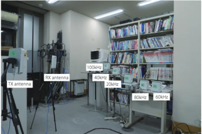
3.3 Digital MSMA in an Indoor Wireless Environment To evaluate the performance of MSMA interference rejec- tion subjected to wireless propagation, we conducted an indoor wireless communications experiment with five pro- totype sensors 1∼5, as shown in Figs. 13 and 14. We used two circular polarized antennas in a bi-static configuration – separated transmitting and receiving antennas. The gain of the antennas are 6 dBi. The transmission power is 23 dBm.
The distance between the reader and the prototype sensors is about 2 m. In the experiment, sensors 1∼5 use 20 kHz,
Fig. 13 Digital MSMA indoor experiment schematics.
Fig. 14 The indoor experiment was conducted in our laboratory.
40 kHz, 60 kHz, 80 kHz and 100 kHz subcarriers, respec- tively withms=4 and 10 kHz bandwidth each. Predefined signal patterns, generated by the MCU in each sensor, were used as sensor data in this experiment.
In this arrangement, the first and second harmonics of sensor 1 interfere with sensor 3 and sensor 5 channels, re- spectively. The packet structure is the same as that in Fig. 9.
CIR in the channels of sensor 3 and 5 were estimated by measuring the harmonics power by switching off sensor 3 or 5, and signal power by switching offsensor 1. The po- sitions of the five sensors were changed six times to yield different CIR patterns. We collected at least 10,000 packets from each sensor to calculate packet error rate.
The packet error rates of sensors 3 and 5 with and without MSMA interference rejection are shown in Fig. 15, in which the measurements with and without MSMA inter- ference are represented by triangular and circular markers.
The packet error rates in the wired experiment (Fig. 11, ms=4) are overwritten by solid lines for comparison.
Although the measured packet error rate characteristics for both with and without MSMA interference are degraded by several decibels from those of the wired experiment re- sults, the contribution of interference rejection is clearly shown in the result. At CIR=5 dB, the packet error rate im- provement with MSMA interference rejection exceeds one hundredth, which is equivalent to the wired experiment re-
Fig. 15 MSMA interference rejection performance in the indoor experi- ment.
sult in Fig. 11. The result shows that the alternate subcarrier subcarrier spacing works in real world propagation environ- ment.
4. Conclusion
Because of the harmonics produced by the digitally mod- ulated subcarrier, digital MSMA may involve reverse inter- ference — interferences from high subcarrier frequency sen- sors to low subcarrier frequency sensors. The reverse inter- ference deteriorates the convenient spectral characteristics among the interfering and interfered sensors. Straightfor- ward implementation of the interference rejection algorithm using harmonics replicas may not work in digitally modu- lated MSMA as in the case of analog modulation. The prob- lem can be solved by properly securing subcarrier spacing;
specifically, in the alternate arrangement. The frequency- efficient spacing can alleviate reverse interference, and can still allow a fairly dense subcarrier allocation, while pre- serving the original processing gain of approximately 5 dB with one hundredth packet error rate improvement.
Acknowledgments
This research and development work was supported by the MIC/SCOPE #185003004.
References
[1] K. Smarsly, K. Dragos, and J. Wiggenbrock, “Machine learning techniques for structural health monitoring,” 8th European Work- shop on Structural Health Monitoring, pp.1–10, 2016.
[2] H. Sohn, C. Farrar, F. Hemez, D. Shunk, D.W. Stinemates, B.R.
Nadler, and J.J. Czarnecki, “A review on structural health monitor- ing literature: 1996-200,” Technical Report, Los Alamos National Laboratory, 2004.
[3] A. Deivasigamani, A. Dalirim, C.H. Wang, and S. John, “A review of passive wireless sensors for structural health monitoring,” Modern Applied Science, vol.7, no.2, pp.57–76, 2013.
[4] C. Boyer and S. Roy, “Backscatter communication and RFID: Cod- ing, energy, and MIMO analysis,” IEEE Trans. Commun., vol.62, no.3, pp.770–785, 2014.
[5] K. Han and K. Huang, “Wirelessly powered backscatter communi- cations networking: Modeling, coverage, and capacity,” IEEE Trans.
Wireless Commun., vol.16, no.4, pp.2548–2561, 2017.
[6] V. Talla and J. Smith, “Hybrid analog-digital backscatter: A new approach for battery-free sensing,” IEEE RFID, pp.74–81, 2013.
[7] J. Mitsugi, N. Rajoria, Y. Kawakita, and H. Ichikawa, “Wireless and batteryless vibration testing of space structures with implanted LSI sensors,” 68th International Astronautical Congress (IAC), IAC-17, C2, X39637, 2017.
[8] “ISO/IEC 18000-63, Information Technology — Radio frequency identification for item management —, Part 63 parameters for air interface communications at 860 MHz to 960 MHz type C,” 2015.
[9] J. Mitsugi and Y. Kawakita, “Efficient frequency sharing of base- band and subcarrier coding UHF RFID systems,” IEICE Trans.
Commun., vol.E92-B, no.12, pp.3794–3802, Dec. 2009.
[10] D. Bharadia, K.R. Joshi, and S.M. Kotaru, “BackFi: High through- put WiFi backscatter,” ACM SIGCOMM, pp.283–296, 2015.
[11] P. Zhang, M. Rostami, P. Hu, and D. Ganesan, “Enabling practi- cal backscatter communication for on-body sensors,” ACM SIG- COMM, pp.370–383, 2016.
[12] A.B. Noel, A. Abdaoui, T. Elfouly, M.H. Ahmed, A. Badawy, and M. Shehara, “Structural health monitoring using wireless sensor net- works: A comprehensive survey,” IEEE Commun. Surveys Tuts., vol.19, no.3, pp.1403–1423, 2017.
[13] X. Fu, A. Pedross-Engel, D. Arnitz, C.M. Watts, and M.S. Reynolds,
“Simultaneous imaging, sensor tag localization, and backscatter up- link via synthetic aperture radar,” IEEE Trans. Microw. Theory Techn., vol.66, no.3, pp.1570–1578, 2018.
[14] R.Z. Doany, C. Lovejoy, K. Jones, and H. Stern, “A CDMA-based RFID inventory system: A CDMA approach as a solution for de- creased power consumption,” IEEE International Conference on RFID, pp.1–4, 2016.
[15] E. Vahedi, R.K. Ward, and I. Blake, “Performance analysis of RFID protocols: CDMA versus the standard EPC Gen-2,” IEEE Trans.
Autom. Sci. Eng., vol.11, no.4, pp.1250–1261, 2014.
[16] P. Hu, P. Zhang, and D. Ganesan, “Laissez-Faire: Fully asymmetric backscatter communication,” ACM SIGCOMM, pp.255–267, 2015.
[17] G. Vannuci, A. Bletsas, and D. Leigh, “A software-defined radio sys- tem for backscatter sensor networks,” IEEE Trans. Wireless Com- mun., vol.7, no.6, pp.2170–2179, 2008.
[18] K.A.S. Immink, Codes for Mass Data Storage Systems, Chap 8 DC- balanced Codes, Shannon Foundation Publishers, 2004.
[19] M. Varner, R. Bhattacharjea, and G.D. Durgin, “Realizing ReMoRa (reflection of modulated radio) ambient scatter communication links with perfect pulses,” IEEE J. Radio Freq. Identif., vol.1, no.1, pp.59–
67, 2017.
[20] B.P. Degnan and G.D. Durgin, “Aynchronous trigger modulation for RFID systems,” IEEE Conference on RFID Technology and Appli- cations, pp.153–158, 2015.
[21] Y. Igarashi, Y. Sato, Y. Kawakita, J. Mitsugi, and H. Ichikawa, “Fea- sibility study on simultaneous data collection from multiple sensor RF tags with multiple subcarriers,” IEEE RFID, 2014.
[22] N. Rajoria, Y. Igarashi, J. Mitsugi, Y. Kawakita, and H. Ichikawa,
“Concurrent backscatter streaming from batteryless and wireless sensor tags with multiple subcarrier multiple access,” IEICE Trans.
Commun., vol.E100-B, no.12, pp.2121–2128, Dec. 2017.
[23] J. Mitsugi, Y. Kawakita, K. Egawa, and H. Ichikawa, “Perfectly syn- chronized streaming from digitally modulated multiple backscatter sensor tags,” IEEE Conference on RFID Technology and Applica- tion (RFID-TA), 2018.
[24] H. Chenling and H. Min, “New method of synchronization for RFID digital receivers,” IEEE Solid-State and Integrated Circuit Technol- ogy, pp.1595–1597, 2016.
Jin Mitsugi received the B.S. from Nagoya University in 1985, M.S. and Ph.D. from Tokyo University in 1987 and 1996, respectively. He had been with NTT laboratory since 1987 pur- suing a research and development on satellite communication system. He has been with Keio University since 2004. His research interests are network RFID, sensor network system, satellite communications and operations research
Yuki Sato received B.A., M.A. and Ph.D.
from Keio University in 2012, 2013 and 2017, respectively. He is currently a project research associate in Graduate School on Media and Governance, Keio University. His research in- terests are RFID, unique identification technolo- gies and their information systems, Internet of Things and wireless communications.
Yuusuke Kawakita received B.A., M.A.
degree and Ph.D. from Keio University in 2000, 2002 and 2008, respectively. He is an associate professor at Kanagawa Institute of Technology.
His present research interests focus on the ubiq- uitous sensing and its platform architecture.
Haruhisa Ichikawa received B.S., M.S., and Dr.Eng. degrees in electrical engineering from the University of Tokyo in 1974, 1975 and 1989, respectively. He joined NTT Laboratories in 1976, where he was engaged in fundamental research on communications software and dis- tributed computing. He created and conducted many R&D projects for software, Internet, in- formation sharing platform and ubiquitous net- works, including business incubation. He was Executive Director of NTT Science and Core Technology Laboratory Group till 2007. He joined the University of Electro-Communications in 2007 and is a professor emeritus.