Analysis and Design of Robust Stabilizing
Modified Repetitive Control Systems
Zhongxiang Chen
GUNMA UNIVERSITY
ABSTRACT
In control system practice, high precision tracking or attenuation for periodic signals is an important issue. Repetitive control is known as an effective approach for such control problems. The internal model principle shows that the repetitive control system which contains a periodic generator in the closed-loop can achieve zero steady-state error for reference input or completely attenuate disturbance. Due to its simple structure and high control precision, repetitive control has been widely applied in many systems. To improve existing results on repetitive control theory, this thesis presents theoretical results in analysis and design repetitive control system. The main work and innovations are listed as follows:
We propose a design method of robust stabilizing modified repetitive controllers for multiple-input/multiple-output plants with uncertainties. The parameterization of all robust stabilizing modified repetitive controllers for multiple-input/multiple-output plant with uncertainty is obtained by employing H∞ control theory based on the Riccati equation. The robust stabilizing controller contains free parameters that are designed to achieve desirable control characteristic. In addition, the bandwidth of low-pass filter has been analyzed. In order to simplify the design process and avoid the wrong results obtained by graphical method, the robust stability conditions are converted to LMIs-constraint conditions by employing the delay-dependent bounded real lemma. When the free parameters of the parameterization of all robust stabiliz-ing controllers is adequately chosen, then the controller works as robust stabilizstabiliz-ing modified repetitive controller.
For a time-varying periodic disturbances, we give an design method of an opti-mal robust stabilizing modified repetitive controller for a strictly proper plant with time-varying uncertainties. A modified repetitive controller with time-varying delay structure, inserted by a low-pass filter and an adjustable parameter, is developed for this class of system. Two linear matrix inequalities LMIs-based robust stability con-ditions of the closed-loop system with time-varying state delay are derived for fixed
parameters. One is a delay-dependent robust stability condition that is derived based on the free-weight matrix. The other robust stability condition is obtained based on the H∞ control problem by introducing a linear unitary operator. To obtain the desired controller, the design problems are converted to two LMI-constrained opti-mization problems by reformulating the LMIs given in the robust stability conditions. The validity of the proposed method is verified through a numerical example.
Contents
Chapter1 Introduction . . . . 1
1.1 Background . . . 2
1.2 Repetitive control principle . . . 3
1.3 Modified repetitive controller . . . 5
1.4 Review on modified repetitive control system design . . . 8
1.4.1 Frequency domain analysis-based design method . . . 9
1.4.2 Linear matrix inequality-based design method . . . . 10
1.4.3 H∞ robust design method . . . 11
1.4.4 Two-degree-of-freedom structure design method . . . 12
1.4.5 Two-dimensional-based design method . . . 13
1.4.6 Parameterization design method . . . 16
1.4.7 Existing problems . . . 18
1.5 Organization of the thesis . . . 19
Chapter2 Robust Stabilizing Problem for Multiple-Input/Multiple-Output Plants . . . . 23
2.1 Introduction . . . 23
2.2 Problem Formulation . . . 26
2.3 The parameterization of all robust stabilizing modified repet-itive controllers for MIMO plants . . . 28
2.4 Control characteristics . . . 34
2.5 Design parameters . . . 37
2.5.1 Design parameters for control performance . . . 37
2.5.2 Design parameters for robust stability conditions . . 39
2.5.3 Robust stability condition based on linear matrix in-equalities (LMIs) . . . 43
2.6 Numerical example . . . 46
2.7 Conclusions . . . 54
Chapter3 Robust Stabilizing Problem for Time-varying periodic Sig-nals . . . . 57
3.1 Introduction . . . 57
3.2 Problem statement and preliminaries . . . 60
3.3 Robust stability conditions . . . 65
3.4 Design procedure . . . 76
3.5 Numerical example . . . 77
3.6 Conclusions . . . 80
Chapter4 Conclusions and Future Work . . . . 81
4.1 Conclusions . . . 81
4.2 Future Work . . . 82
Bibliography . . . . 87
List of Figures
1.1 Generator of periodic signals with period-time L[s] . . . 4
1.2 Conventional repetitive control system . . . 4
1.3 Conventional modified repetitive control system . . . 6
1.4 Bode plots of repetitive controller CR(s) (a) and modified repetitive controller CRM(s) (b) . . . 8
1.5 Two-degree-of-freedom modified repetitive control system . . . 12
2.1 Modified repetitive control system with uncertainty . . . 26
2.2 Block diagram of H∞ control problem . . . 29
2.3 Closed-loop system for Q(s)∈ H∞ and ∥Q(s)∥∞< 1 . . . 39
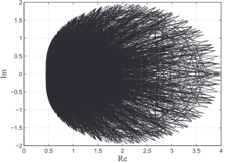
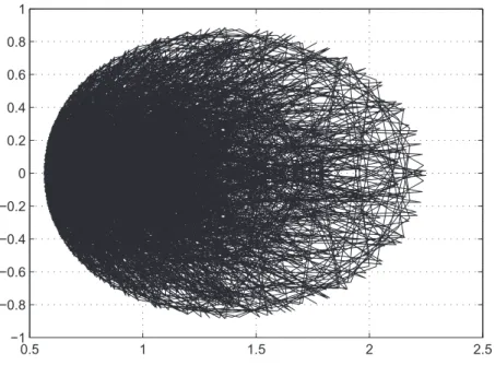
2.4 The nyquist plot of det(Qd1(s) + Qd2(s)e−sT) . . . 48
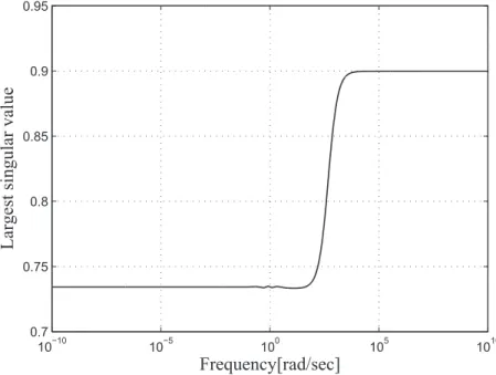
2.5 Largest singular value plot of Q(s) . . . 49
2.6 The nyquist plot of det(Qd1(s) + Qd2(s)e−sT) when τd 1,2= 0.001 . . 50
2.7 Largest singular value plot of Q(s) when τd 1,2= 0.001 . . . 50
2.8 Largest singular value plot of ∆(s) and gain plot of WT(s) . . . . 51
2.9 Response of the error e(t) for the reference input r(t) . . . . 52
2.10 Response of the output y(t) for the disturbance ¯d(t) . . . . 53
2.11 Response of the output y for the disturbance ˜d(t) . . . . 54
3.1 Flat cam grinding system . . . 58
3.2 Rotation speed of servomotor . . . 58
3.3 The new repetitive control system . . . 62
3.4 The repetitive control system with uncertainties . . . 63
3.5 Equivalent diagram of Figure 3.4 . . . 71
3.6 Disturbance signal used in simulations . . . 78 3.7 Time-varying period, τ (t) . . . 78 3.8 Derivative of τ (t), ˙τ (t) . . . . 78 3.9 Response of the output y(t) for the disturbance d(t) with our repetitive
controller . . . 79 3.10 Response of the output y(t) for the disturbance d(t) without our
repet-itive controller . . . 79
1
Chapter 1
Introduction
People often completely master a new learned skill through repetition. By repeating the same action, a person gradually comes to understand the essential points, and achieves a significant efficiency and precision. This process, with self-learning and gradual progress, is a repetitive task. An investigation of the process reveals two main characteristics:
1. the same action is performed;
2. the action currently being performed is based on the action performed in the previous repetition.
These two characteristics imply that it is a periodic repetitive task.
Manufacturing and industrial applications often have plants that perform repeti-tive tasks. In these situations, exploiting the periodic properties of the design problem is an important part in maximizing performance. Inoue et al. [1, 2] devised a new control strategy called repetitive control that adds a human-like learning capability to a control system. The new type of control system for periodic repetitive task is named as repetitive control system. A repetitive control system is different from other types of control systems in that it possesses a self-learning capability. For example, Inoue et al. [1] designed a Single-Input/Single-Output repetitive control system for supplying power for the magnet of a proton synchrotron that tracks a desired
period-2 CHAPTER 1. INTRODUCTION
ic reference input, namely excitation current. After self-learning for 16 periods, the relative tracking precision reached 10−4. This high precision was unobtainable by any other control method at that time. As a result, the theory and design methods of the repetitive control system immediately received a great deal of attention, and it is now widely used in many fields from aerospace to public welfare systems.
1.1
Background
In practical applications, tracking and/or rejecting the periodic reference input and/or disturbance signals are of great significance. For example, in industrial manipulators executing operations of picking, placing or painting, machine tools and magnetic disk or CD drives, the control systems are usually required to track or reject periodic exogenous signals with high control precision. The repetitive control theory provides an achievable and practicable theoretical foundation and solution.
At present, repetitive control has been widely applied in various high-precision control systems. As a simple learning control method, repetitive control has many advantages such as simple algorithm, insensitivity of the system performance to pa-rameters, small online computation, high-precision, suitability for fast motion con-trol and so on. All these characteristics are required for many control problems with periodic exogenous signals. With the improvement of technical level of mod-ern industry, the requirement for the design of repetitive control system is high-er than evhigh-er. For example, in many shigh-ervo systems, the requirements are not only high steady state accuracy, but also good transient characteristics. That mean-s the demean-sign of repetitive control mean-symean-stem mean-should optimize the mean-steady mean-state perfor-mance and transient characteristics [3]. For the plants with uncertainties, such as SPWM inverter requires the design method satisfying the robust stability [4, 5, 6]. Some plants require the variable to learn in an iteration-independent manner like the robot motion control [7]. That has high demands on the adjusting function
1.2. REPETITIVE CONTROL PRINCIPLE 3
of parameters. In addition, the repetitive control system with independently regulate and control manner should be established.
As the development of the application of the repetitive control method, the for-mation of new problem in the practical control system leads to further developed and improved of the repetitive control system theory and design methods. Therefore, study on design method of repetitive controllers and deeply reveal the nature of the repetitive control systems have an important theoretical and practical significance.
1.2
Repetitive control principle
Repetitive control is a control scheme applied to plants that must track a periodic trajectory or reject a periodic disturbance with the explicit use of the periodic feature of the trajectory or disturbance.
It was first introduced by Inoue et al. and applied to the control of a power supply for a proton synchrotron [1] and a contouring servo system [2] . Since then, repetitive control has been applied to many problems, including:
• power supply systems ([1, 8]), • robotic manipulators ([9, 10]), • computer disk drives ([11, 12]), • CD tracking ([13, 94]),
• motor control ([15, 16]),
• thickness control in sheet metal rolling ([17]), • peristaltic pump ([18]),
• cold rolling process control ([19]), • navicular machining ([20]),
4 CHAPTER 1. INTRODUCTION
• vibration attenuation ([21, 22]) and • distributed solar collector ([23, 24, 25]).
The Internal Model Principle (IMP) proposed by Francis and Wonham [26] plays an important role in repetitive control system. The IMP states that if a reference or disturbance signal can be regarded as the output of an autonomous system, including this system in a stable feedback loop guarantees asymptotically perfect tracking or rejecting performance. Figure 1.1 shows the more frequently used generator of pe-riodic signals with a period-time L[s]. In this figure, a finite length input u(t) from
e
à
sL
+
+
u
(t)
r
( t )
Figure 1.1: Generator of periodic signals with period-time L[s]
t = 0 to t = L yields an output r(t) that is a periodic, i.e.,
r(t) = u(t), 0≤ t ≤ L r(t− L), L ≤ t . (1.1)
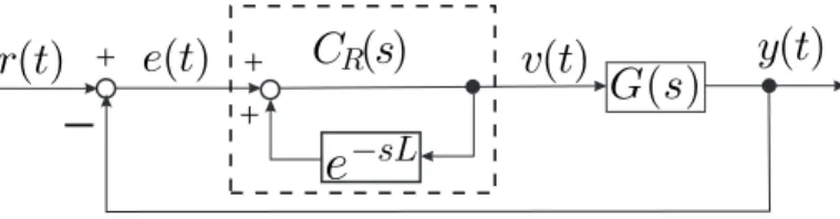
An IMP-based repetitive controller incorporates this generator in a control loop as shown in Figure 1.2. In this control system, we want the control output y(t) to track
+ +
-+y(t)
e
àsLv(t)
G
(s)
C
R(s)
e(t)
r(t)
Figure 1.2: Conventional repetitive control system
1.3. MODIFIED REPETITIVE CONTROLLER 5
function of the repetitive controller CR(s)(dotted line) is described as
CR(s) = 1
1− e−sL, (1.2)
where L is a constant equal to the period-time of the reference input, r(t). This period time is known or accurately measured. Since
CR(jωk) =
1
1− e−jωkL =∞, ωk =
2kπ
L , k = 0, 1, 2,· · · , (1.3)
the gain of the repetitive controller is infinite at the angular frequencies of the funda-mental and harmonic waves of a signal with period-time L[s]. Note that the tracking error of the repetitive control system in Figure 1.2 is given by
E(s) = SR(s)R(s), (1.4) and SR(s) = 1 1 + CR(s)G(s) = 1 CR(s) 1 1 CR(s)+ G(s) , (1.5)
where SR(s) is the sensitivity function of the system. Clearly, including the internal model as a repetitive controller results in an infinite loop gain and hence, a zero closed-loop sensitivity at the angular frequencies of the fundamental and harmonic waves. Consequently, the periodic signal with a period-time L[s] can be perfectly tracked or rejected by this closed-loop system called as periodic performance. Hence, when a control system contains repetitive controller CR(s), it tracks the periodic reference input with high control accuracy.
However, it is impossible to design stabilizing repetitive controller for strictly proper plant, because the repetitive control system is a neutral type of time-delay system. To design a repetitive control system that follows any periodic reference input without steady state error, the plant must be biproper.
1.3
Modified repetitive controller
The nonexistence of a repetitive controller for a strictly proper plant has been detailed by Hara et al. in [27]. According to the servo theory, it is well-known that output
6 CHAPTER 1. INTRODUCTION
regulation is possible only when plant zeros do not cancel the poles of the reference signal generator. Applying this principle to the present situation, although it is nonclassical, we see that this principle is not satisfied for a strictly proper plant G(s), for G(s) has infinity as its zero, whereas the generator of the periodic signal has a pole of arbitrarily high frequency. To put it differently, if G(s) is strictly proper, then it integrates the input at least once, and hence the output will be smoothed out to some extent, thereby making it impossible to track a signal with an infinity sharp edge, i.e., a signal contain arbitrarily high-frequency modes.
+
+
-+
y(t)
q(s)e
àsLv(t)
G(s)
C
RM(s)
e(t)
r(t)
Figure 1.3: Conventional modified repetitive control system
However, the actually control plant is strictly proper and has any relative degree. This is unfortunate, but not entirely irreconcilable since this is caused by the appar-ently unrealistic demand of tracking any periodic signal, which contains arbitrarily high-frequency modes. It is therefore natural to expect that the stability condition can be relaxed by reducing the loop-gain of the repetitive compensator in a higher frequency range. This leads to the idea of a modified repetitive control system [27, 28] shown in Figure 1.3. In this control system, the delay element e−sL is replaced by q(s)e−sL for a suitable proper stable rational q(s), namely low-pass filter with following frequency characteristics:
i ) q(jω)≃ 1 for |ω| ≤ ωc,
ii ) |q(jω)| ≤ ρ < 1 for |ω| > ωc,
1.3. MODIFIED REPETITIVE CONTROLLER 7
by a simple first-order system
q(s) = 1 1 + τ s, τ > 0 (1.6) or q(s) = 1 + τ2s 1 + τ1s , τ1 > τ2 > 0. (1.7)
Then, the transfer function of the modified repetitive controller is
CRM(s) =
1
1− q(s)e−sL (1.8)
and the corresponding sensitivity function of the modified repetitive control system becomes SRM(s) = 1 CRM(s) 1 1 CRM(s) + G(s) . (1.9)
The utilization of the low-pass filter, q(s), changes the tracking characteristics. For example, consider the widely used low-pass filter q(s) = 1/(τ s + 1). Bode plots of repetitive controller CR(s) and modified repetitive controller CRM(s) for L = 2π s in Figure 1.4 show that, when τ = 0.001s, the gains of CRM(s) at the angular fre-quencies of the fundamental and second harmonic drop from infinity to 56.57[dB] and 67.85[dB], respectively. Therefore, a steady-state tracking error arises when CRM(s) is employed in a modified repetitive-control system. Furthermore, if the cutoff angu-lar frequency, ωc = 1/τ , of low-pass filter is made 100 times smaller, i.e., τ = 0.1s, then the gains just mentioned decrease dramatically to 45.97[dB] and 34.44[dB]. This greatly increases the steady state tracking error. From above discussion, it is clear that, by introducing the low-pass filter, the robustness stability of repetitive control systems was guaranteed, but at cost of degrading performances at high frequencies.
Therefore, in order to obtain good tracking precision or disturbance attenuation performance, the cutoff angular frequency of the low-pass filter must be as high as possible. However, the investigation of the stability of modified repetitive control system reveals that the restriction of frequency band to be tracked is imposed only
8 CHAPTER 1. INTRODUCTION 0.5 0.6 0.7 0.80.9 1 2 3 4 5 6 7 8 9 10 −10 0 20 40 60 ω [rad/s] G a in [d B ] b τ=0.1 τ=0.001 0.5 0.6 0.7 0.80.9 1 2 3 4 5 6 7 8 9 10 −10 0 20 40 60 ω [rad/s] G a in [d B ] a
Figure 1.4: Bode plots of repetitive controller CR(s) (a) and modified repetitive controller CRM(s) (b)
for non-minimal phase plants [29]. This results in the tradeoff problem among steady state accuracy, robustness and transient response of the control system.
1.4
Review on modified repetitive control system
design
The design problems of modified repetitive control systems are mainly to choose and optimize the dynamic compensator and the low-pass filter. The selection of parame-ters involves robustness stability, tracking performance, attenuation performance and tradeoff problem. Since introduction of repetitive control to the control community, a great deal of research effort has been devoted to the design methods for modified
1.4. REVIEW ON MODIFIED REPETITIVE CONTROL SYSTEM DESIGN 9
repetitive control system. What’s more, various structures and algorithms have been proposed in existing literature. In this section, a detailed review of the main work on the design methods for modified repetitive control system is specified.
1.4.1
Frequency domain analysis-based design method
The frequency domain analysis and synthesis method is a main approach for modified repetitive control system design. In [1, 30], some general design guidelines were devel-oped. Srinivasan et al. [31] analyzed the single-input/single-output continuous time repetitive control system using the regeneration spectrum. It has been proved that shaping the regeneration spectrum is an effective way to alter the relative stability and transient response of system. A modified repetitive control scheme by shap-ing both regeneration spectrum and the sensitivity function was proposed in [32]. To achieve a specified level of nominal performance, Srinivasan et al. [33] used the Nevanlinna-Pick interpolation method to modify repetitive controller by optimizing a measure of stability robustness (a weighting function on the complementary sensi-tivity function). To offer an ease of multi-objective design, Guvenc [34] described a graphical repetitive controller design procedure, which is based on mapping frequency domain performance specifications of sensitivity function magnitude and regeneration spectrum to the controller parameter space. Moon et al. [35] designed of a repetitive controller by a graphical technique based on the frequency domain analysis of a linear interval system.
Another frequency domain analysis method is to make the magnitude of system sensitivity function in the middle of two adjacent harmonics as an optimization ob-jective to design modified repetitive control system [36]. In order to improve the tracking or attenuation performance at the high frequencies for reference input or disturbance, Kim and Tsao modified the structure of low-pass filter to make the sen-sitivity approximately squared by comparing with original modified repetitive control system. This method improves the tracking or attenuation performance of system at
10 CHAPTER 1. INTRODUCTION
harmonics.
From Figure 1.4, we can find that the introduction of the low-pass filter q(s), while improving the system stability, also introduce phase lag which shifts the frequency at which the gain of the repetitive controller reaches the maximum value. To compensate the phase lag induced by q(s), Sugimoto et al. [37] proposed to modify the dead time term so that the maximum gain is exactly situated at the fundamental frequency of the periodic signal. Extending this work, Chen and Lin [38] introduced a lead compensator to widen the bandwidth of low-pass filter and improve system gain at high frequencies. The optimal modified repetitive controller is obtained by solving two optimization problems.
1.4.2
Linear matrix inequality-based design method
Linear matrix inequality (LMI), regarded as an effective tool to deal with system and control problem, has been applied to design and analysis for modified repetitive control systems. One of the first papers to consider the design of the repetitive controller as a convex optimization problem was [39]. In that paper, LMI-conditions are derived to design the low-pass filter associated with the repetitive structure. It is important to point out that in this work the authors only presented conditions to verify whether a priory fixed cutoff frequency of the low-pass filter results in a feasible solution and not focus in the design of the stabilizing controller. Latter, this work was extended and analyzed in [13, 40, 41, 42, 43] and references therein. A simultaneous optimization of the low-pass filter and state-feedback controller was design by She et al. [43] based on LMIs. They proposed an iterative algorithm to obtain the best combination of low-pass filter and state-feedback controller.
For linear systems with time-varying state-delay [44] or input delay [41], the ro-bustness stability criterion is derived in the form of LMI and the design problem of modified repetitive controller is transformed to an LMI-constrained optimization problem. However, the control parameter obtained by solving LMI feasible
prob-1.4. REVIEW ON MODIFIED REPETITIVE CONTROL SYSTEM DESIGN 11
lem has some conservation that restricts the control performance. To reduce the conservatism, free weighting matrices and descriptor model transformation are usu-ally introduced to derive robustness stability conditions. In [45], considering single-input/single-output systems for the presence of control saturation, a modified state-space repetitive control structure is designed and conditions in a ”quasi” LMI form are proposed. Flores et al. [46] generalized the results in [45] to consider multiple-input/multiple-output systems.
1.4.3
H
∞robust design method
In fact, the H∞ control approach has been also widely used in many modified repet-itive control system design [47, 48]. It is mainly used to for solving robustness and optimization problems, and provides a kind of design method of state-feedback con-troller. For instance, Wang et al. [49] proposed a three-step design method for state-feedback controller. Wang and Tsao [50, 51] basing on H∞ control approach, designed a robust stabilizing modified repetitive controller for time-varying periodic signals. Li and Tsao [52] viewed the time-delay element in the internal model as an uncertainty and employed the H∞ control approach to obtain the robust stabil-ity condition and robustness performance. Using the same method, She et al. [53] proposed simultaneous optimization design method by introducing the state-feedback gains. The design problem of modified repetitive controller is converted into convex optimization problem in the form of LMI. Designed a iterative algorithm to calculate the cutoff frequency and state-feedback gains.
To some extent, H∞control method can improve the robust performance of repet-itive control system, but the design of state-feedback controller is still independent of repetitive controller. This may result in some conservatism and affects the trade-off problem between robustness stability and robust performance.
12 CHAPTER 1. INTRODUCTION
1.4.4
Two-degree-of-freedom structure design method
To relieve the burden of the system stability on one controller, a two-degree-of-freedom structure in Figure 1.5 can also be considered, where C(s) is a modified repetitive controller. It contains a feed forward compensator and feedback compensator. Some synthesis procedure for this class of repetitive control system, such as the state-space approach, coprime factorization approach, H∞ optimal design approach and sliding mode variable structure control approach can be found in [2, 4, 28, 29, 54, 55, 56, 57], where the main task is to design the stabilizing controllers.
+ r(s) u(s) + + y(s)
C(s)
d
1(s)
d
2(s)
z(s)
G(s)
+Figure 1.5: Two-degree-of-freedom modified repetitive control system
Peery et al. [54] proposed a two-degree-of-freedom H∞ optimal respective con-trol structure with fixed low-pass filter for Single-Input/Single-Output system. Chen et al. [56, 57] established a two-degree-of freedom modified repetitive controller for the rejection for disturbance and guaranteed the robustness of the system with ac-tuator saturation uncertainties. Dong et al. [55] studied the design method of two-degree-of-freedom modified repetitive controller based on the factorization approach. Yamada et al. [58] designed a modified repetitive control system with feed-forward controller and feedback controller. Sakanushi et al. [59] proposed a design method for two-degree-of-freedom simple repetitive control systems for multiple-input/multiple-output plants. The design method based on two-degree-of-freedom eliminates the influence of the unstable poles to improve stability and robustness. However, there is no systematical approach for selecting the parameters of controllers. The state-space-based synthesis procedure relying on some indirect specifications of performance, for
1.4. REVIEW ON MODIFIED REPETITIVE CONTROL SYSTEM DESIGN 13
example, in the form of noise covariance and weighting matrices, involves currently much trial and error.
1.4.5
Two-dimensional-based design method
A close examination of repetitive control shows that it actually involves two indepen-dent types of actions:
• continuous control within each repetition period and • discrete learning between periods.
From the standpoint of system design, it is difficult to stabilize a repetitive-control system, and all design methods are developed to focus mainly on stability. That is, they do not accurately describe what actually happens, or they do not thoroughly investigate the essence of the control and learning actions with only considering the overall results in the time domain. As a result, researchers impose not only very strict requirements on the plant, but also a limit on how much control performance can be improved [60, 13, 61].
From the repetitive compensator CR(s) shown in Figure 1.2, the control output
v(t) can be represented in time domain as
v(t) = e(t) 0≤ t < L v(t− L) + e(t) t ≥ L (1.10)
where L is a delay element, i.e., the period of reference input r(t), e(t) = r(t)− y(t) is track error of the closed-loop system.
Setting the state-space description of plant is ˙x(t) = Ax(t) + Bu(t), y(t) = Cx(t) + Du(t). (1.11)
14 CHAPTER 1. INTRODUCTION
where x(t) ∈ Rn is the state of plant, u(t) ∈ Rm is control input, and y(t) ∈ Rp is control output. Without losing generality, set the system matrices (A, B, C, D) are controllable and observable. For convenient, set the m = p = 1, i.e., Single-Input/Single-Output system.
The design problem of repetitive control system is design a controller containing
v(t) such that the closed-loop system is stable and the tracking error is convergent to
0 for any reference input with given period L. As a matter of fact, the stable vector
x(t) and control input u(t) when closed-loop system is stable for any given reference
input r(t). However, the difference of state vector ∆x(t) and the difference of control input ∆u(t) between two adjacent periods are convergent to 0. From this aspect, consider the variation of these differences. Setting variable ξ(t)(ξ ∈ {x, y, u, e}) is equal to 0 as t < 0 and
∆ξ(t) = ξ(t)− ξ(t − L) (1.12)
then
∆ ˙x(t) = A∆x(t) + B∆u(t) (1.13)
e(t) = e(t− L) − C∆x(t) − D∆u(t) (1.14) Equation (1.13) and (1.14) demonstrate the control and learn process of the repetitive control process. We divide the infinite interval [0, +∞) into an infinite number of finite intervals, [kL, (k + 1)L)(k = 0, 1,· · · ). Then, for any t ∈ [0, +∞), there exists an interval [kL, (k + 1)L) such that
t = kL + τ, τ ∈ [0, L)
This allows us to write the variable ξ(t) in the time domain as
ξ(t) = ξ(kL + τ ) := ξ(k, τ ),
and
1.4. REVIEW ON MODIFIED REPETITIVE CONTROL SYSTEM DESIGN 15
Then, the equations (1.13) and (1.14) are converted into
∆ ˙x(k, τ ) = A∆x(k, τ ) + B∆u(k, τ ) (1.15)
e(k, τ )− e(k − 1, τ) = −C∆x(k, τ) − D∆u(k, τ) (1.16) Equations (1.15) and (1.16) are represented by vector as
∆ ˙x(k, τ ) e(k, τ )) = A 0 −C 1 ∆x(k, τ ) e(k− 1, τ) + B −D ∆u(k, τ) (1.17)
If we can design a two-dimensional controller such that ∆u(k, τ ) make the con-tinuous/discrete two-dimensional system (1.17) is asymptotically stable, the corre-sponding repetitive control system (1.11) is asymptotically stable and convergent to zero. From these, the design problem of repetitive control system (1.11) is equivalent to stabilization problem of the continuous/discrete two-dimensional system (1.17).
Wu et al. [62] presented a design method of modified repetitive control system for a class of linear system based on two-dimensional continuous/discrete hybrid model. The design problem for the modified repetitive controller is converted in a state-feedback design problem for a continuous-discrete two-dimensional system. And then the design problem is solved by combing two-dimensional Lyapunov theory with LMIs approach. Later, wu et la. [63] proposed a guaranteed cost design method of modified repetitive control system based on two-dimensional hybrid model. Then Zhang et al. [64] designed a modified repetitive control system by using state feedback hybrid model based on two-dimensional hybrid model. This result can be extended to handle a plant with a time-varying uncertainty. Zhou et al. [65] presented a robust modified repetitive control system based on both LMI and two-dimensional hybrid model. It can adjust the control and learning actions individually by adjusting the parameters contained in the LMI.
16 CHAPTER 1. INTRODUCTION
1.4.6
Parameterization design method
Parameterization is a very common method used for dealing with the design problem of control system. This method is based on factorization theory. For parameterization-based design of modified repetitive controlled, Yamada et al have done a lot of work.
1. Minimum phase
A parameterization of all modified repetitive controllers for the strictly proper plants is given by Yamada and Okuyama [66] . Yamada et al. [67] proposed a design method for robust stabilizing modified repetitive controllers without solving the µ synthesis problem. This method is effective for minimum phase plants.
2. Non-minimum phase
Based on [67], Yamada et al. [68, 69] clarified the parameterization of all sta-bilizing mollified repetitive controllers for non-minimum phase systems. And then, Yamada et al. [70] gave a design method for robust stabilizing modified repetitive controllers for non-minimum phase plants such that the frequency range in which the output follows the periodic reference input is not restrict-ed. In [71], the parameterization of all robust stabilizing modified repetitive controllers is given by extending the result in[70].
3. Robust stabilization
Yamada et al. [72] proposed a parameterization of all robust stabilizing simple repetitive controllers such that the controller work as a robust stabilizing modi-fied repetitive controller. Chen [73] solved the robust stabilizing problem for the modified repetitive control system with multiple-input/multiple-output plants. Extending this work, the robust stabilizing modified repetitive controller for multiple-input/multiple-output plants is proposed with specified input-output frequency characteristic [74].
1.4. REVIEW ON MODIFIED REPETITIVE CONTROL SYSTEM DESIGN 17
4. Time-delay
The design method of all stabilizing modified repetitive controllers for time-delay systems with the specified input-output frequency characteristics has been studied by Satoh et al.[75]. Referencing to [68, 69], the parameterization of all robust stabilizing controllers for time-delay plants is obtained [76]. This design method includes a free parameter which is designed to achieve desirable control characteristics.
5. Multiple-input/multiple-output plants
For the multiple-input/multiple-output plants, Yamada et al. [77] have design the modified repetitive controllers based on the references. Chen et al. [78] ob-tained the stabilizing modified repetitive controller by using the free parameter in the parameterization.
6. Two-degree-of-freedom structure for single-input/single-output plants
Yamada et al. [79] proposed the parameterization of all stabilizing two-degree-of-freedom modified repetitive controllers those can specify the input-output characteristic and the feedback characteristic separately. The design of control system with multi-period structure for single-input/single-output plants has been solved in [80].
7. Two-degree-of-freedom structure for multiple-input/multiple-output plants Based on existing literature, the problem of obtaining the parameterization of all stabilizing two-degree-of-freedom modified repetitive controller for multiple-input/multiple-output plants has been solved [81]. In this paper, the input-output characteristic and the feedback characteristic are specified separately. In order to specify the input-output characteristic and the disturbance attenuation characteristic, Chen et al. [82] proposed a design method for two-degree-of-freedom multi-period repetitive controllers for multiple-input/multiple-output systems. The input-output characteristic can be specified independent from the
18 CHAPTER 1. INTRODUCTION
disturbance attenuation characteristic.
All above design methods of modified repetitive controllers are based on the coprime factorization. When control plant has an uncertainty or time-delay, the H∞ control approach will be introduced to simplify the design problem.
1.4.7
Existing problems
The repetitive control technique has been widely applied in many areas since it was proposed. That fully displays its extensive engineering application value, and it has been proven to be an effective control strategy for the control problem of external pe-riodic excitation signal. With the deeply research on the repetitive control theory and widely practicing in diverse areas, the above achievements promote the development of repetitive control, whereas, there are some issues existing:
• In the case of designing the multiple-input/multiple-output modified
repeti-tive control system, the relationship between inputs and outputs should be coordinated to guarantee good control performance. Particularly, for multiple-input/multiple-output plants with uncertainties, the robust stability conditions and the simple design method are indispensable.
• In practical, it is inevitably to deal with the position-dependent (time-varying)
or uncertain periodic signals. For example, to track the time-varying periodic signals, generally transform the linear control plant in the time domain into a nonlinear control plant in the spatial domain, or combine the adaptive control approach. This makes the design problem more complicated. For the periodic signal with uncertain period-time, the perfect performance only can be guaran-teed by using the high-order repetitive controller for a small variation. There is no effective method for this situation.
1.5. ORGANIZATION OF THE THESIS 19
1.5
Organization of the thesis
Most designs of modified repetitive control systems are based on the use of a design model. The relationship between models and the reality they represent is subtle and complex. A mathematical model provides a map from inputs to outputs. The quality of a model depends on how closely its responses match those of the true plant. There is no single fixed model that can respond exactly like the true plant. Hence, we need, at the very least, a set of maps. The term uncertainty refers to the differences or errors between models and reality, and whatever mechanism is used to express these errors will be called a representation of uncertainty. To be practical, consider the problem of bounding the magnitude of the effect of some uncertainty on the nominal plant. In the simplest case, this power spectrum is assumed to be independent of the input. This is equivalent to assuming that the uncertainty is generated by an additive noise signal with a bounded power spectrum; the uncertainty is represented as additive noise. Of course, no physical system is linear with additive noise, but some aspects of physical behavior are approximated quite well using this model. With uncertainties, the design problem of modified repetitive control should consider the robustness of control system. By this reason, this thesis is organized as follows:
In Chapter 2, we propose a design method of robust stabilizing modified repeti-tive controllers for multiple-input/multiple-output plants. The basic idea of robust stabilizing modified repetitive controller is very simple. If the modified repetitive control system is robustly stable for the multiple-input/multiple-output plant with uncertainty, then the modified repetitive controller must satisfy the robustness sta-bility condition. The parameterization of all robust stabilizing modified repetitive controllers for multiple-input/multiple-output plant with uncertainty is obtained by employing H∞ control theory based on the Riccati equation. The robust stabiliz-ing controller contains free parameters that are designed to achieve desirable control characteristic. When the free parameters of the parameterization of all robust
stabi-20 CHAPTER 1. INTRODUCTION
lizing controllers is adequately chosen, then the controller works as robust stabilizing modified repetitive controller. In this chapter, the bandwidth of low-pass filter has been analyzed. In order to simplify the design process and avoid the wrong results obtained by graphical method, the robust stability conditions are converted to LMIs-constraint conditions by employing the delay-dependent bounded real lemma. The effectiveness of this proposed method is illustrated by a numerical example.
In Chapter 3, we address the problem of designing an optimal robust stabilizing modified repetitive controller for a strictly proper plant with time-varying uncertain-ties. This repetitive control system is used to reject position-dependent (time-varying) periodic disturbances. A modified repetitive controller with time-varying delay struc-ture, inserted by a low-pass filter and an adjustable parameter, is developed for this class of system. Two linear matrix inequalities (LMIs)-based robust stability con-ditions of the closed-loop system with time-varying state delay are derived for fixed parameters. One is a delay-dependent robust stability condition that is derived based on the free-weight matrix. The other robust stability condition is obtained based on the H∞ control problem by introducing a linear unitary operator. To obtain the desired controller, the design problems are converted to two LMI-constrained opti-mization problems by reformulating the LMIs given in the robust stability conditions. The validity of the proposed method is verified through a numerical example.
Chapter 4 summarizes the result of the present study by the conclusion and states the future work of the modified repetitive control system.
1.5. ORGANIZATION OF THE THESIS 21
Notation
R the set of real numbers.
R+ R ∪ {∞}.
R(s) the set of real rational functions with s.
RH∞ the set of stable proper real rational functions.
H∞ the set of stable causal functions.
D⊥ orthogonal complement of D, i.e., [ D D⊥ ] or D D⊥ is unitary. AT transpose of A. A† pseudo inverse of A. ρ({·}) spectral radius of {·}. ¯
σ({·}) largest singular value of{·}.
∥{·}∥∞ H∞ norm of {·}.
A B
C D
represents the state space description C(sI − A)−1B + D. Rn the n-dimensional Euclidean space.
Rn×n the set of all n× n real matrices.
I the identity matrix.
L2[0, tf] the set of function f (t) satisfies ∫tf
0 f (t)f (t)dt <∞.
∗ the symmetric terms in a symmetric matrix as A B ∗ C = A B BT C .
23
Chapter 2
Robust Stabilizing Problem for
Multiple-Input/Multiple-Output
Plants
2.1
Introduction
In this chapter, we examine a design method for robust stabilizing modified repetitive controllers using the parameterization of all robust stabilizing modified repetitive controllers for multiple-input/multiple-output plants. A repetitive control system is a type of servomechanism for periodic reference inputs. That is, the repetitive control system follows the periodic reference input without steady state error, even if a periodic disturbance or uncertainty exists in the plant [8, 83, 84, 85, 86, 28, 89, 87, 88, 9, 90, 91, 92]. It is difficult to design stabilizing controllers for the strictly proper plant, because a repetitive control system that follows any periodic reference input without steady state error is a neutral type of time-delay control system [90]. To design a repetitive control system that follows any periodic reference input without steady state error, the plant must be biproper [84, 85, 86, 28, 89, 87, 88, 9, 90]. Ikeda and Takano [91] pointed out that it is physically difficult for the output to
24
CHAPTER 2. ROBUST STABILIZING PROBLEM FOR MULTIPLE-INPUT/MULTIPLE-OUTPUT PLANTS
follow any periodic reference input without steady state error. In addition, they showed that the repetitive control system is L2 stable for periodic signals that do
not include infinite frequency signals if the relative degree of the controller is one. In practice, the plant is strictly proper and has two or more relative degree. Many design methods for repetitive control systems for strictly proper plants those have any relative degree have been given [84, 85, 86, 28, 89, 87, 88, 9, 90]. These studies are divided into two types. One uses a low-pass filter [84, 85, 86, 28, 89, 87, 88, 9] and the other uses an attenuator [90]. The latter is difficult to design because it uses a state variable time-delay in the repetitive controller [90]. The former has a simple structure and is easily designed. Therefore, the former type of repetitive control system is called the modified repetitive control system [84, 85, 86, 28, 89, 87, 88, 9].
When modified repetitive control design methods are applied to real systems, the influence of uncertainties in the plant must be considered. In some cases, uncertain-ties in the plant make the modified repetitive control system unstable, even though the controller was designed to stabilize the nominal plant. The stability problem with uncertainty is known as the robust stability problem [93]. The robust stability problem of modified repetitive control systems was considered by Hara et al. [87]. The robust stability condition for modified repetitive control systems was reduced to the µ synthesis problem [87], but the µ synthesis problem cannot be solved ana-lytically. That is, in order to solve the µ synthesis problem, we must solve an H∞ problem iteratively using the D− K iteration method. Furthermore, the convergence of iterative methods to solve the µ synthesis problem is not guaranteed. Yamada et al. tackled this problem and proposed a design method for robust repetitive control systems without solving the µ synthesis problem [67]. In this way, several design methods of robust stabilizing modified repetitive controllers have been considered.
On the other hand, there exists an important control problem to find all stabiliz-ing controllers named the parameterization problem [96, 97, 95, 98, 99]. Yamada and
2.1. INTRODUCTION 25
Satoh clarified the parameterization of all robust stabilizing modified repetitive con-trollers [100]. However, the method by Yamada and Satoh [100] cannot be applied to multiple-input/multiple-output systems. Because, the method by Yamada and Satoh [100] uses the characteristic of single-input/single-output system. Many real plants include multiple-input and multiple-output. In addition, the parameterization is useful to design stabilizing controllers [96, 97, 98, 99]. Therefore, the problem of obtaining the parameterization of all robust stabilizing modified repetitive controllers for multiple-input/multiple-output plants is important. Chen et al. examined this problem and clarified the parameterization of all robust stabilizing modified repetitive controllers for multiple-input/multiple-output plants [73]. However, in [73], complete proof of the theorem for the parameterization of all robust stabilizing modified repet-itive controllers for multiple-input/multiple-output plants was omitted on account of limiting space. In addition, using the obtained parameterization of all robust stabiliz-ing modified repetitive controllers for multiple-input/multiple-output plants, control characteristics are not examined. Furthermore, a design method for robust stabiliz-ing modified repetitive control system for multiple-input/multiple-output plants are not described. Therefore, we cannot find whether or not the parameterization of all robust stabilizing modified repetitive controllers for multiple-input/multiple-output plants in [73] is valid.
In this chapter, we give a complete proof of the theorem for the parameterization of all robust stabilizing modified repetitive controllers for multiple-input/multiple-output plants omitted in [73] and show effectiveness of the parameterization of all robust stabilizing modified repetitive controllers for multiple-input/multiple-output plants. First, we give a complete proof of the theorem for the parameterization of all robust stabilizing modified repetitive controllers for multiple-input/multiple-output plants omitted in [73]. Next, we clarify control characteristics using the parameteri-zation in [73]. The generalized design method for free parameters has been proposed. Furthermore, the bandwidth limitation of cutoff frequency of low-pass filter which is
26
CHAPTER 2. ROBUST STABILIZING PROBLEM FOR MULTIPLE-INPUT/MULTIPLE-OUTPUT PLANTS
used to specify disturbance attenuation characteristic is obtained by analyzing the robust stability condition. In order to simplify the design process and avoid the wrong results obtained by graphical method, the robust stability conditions are converted into LMIs-constraint conditions by employing the delay-dependent bounded real lem-ma. In addition, a design procedure using the parameterization is presented. Finally a numerical example is illustrated to show the effectiveness of the proposed method.
2.2
Problem Formulation
Consider the modified repetitive control system in Figure 2.1 y = G(s)u + d u = C(s)(r− y) , (2.1)
where G(s)∈ Rp×p(s) is the multiple-input/multiple-output plant, G(s) is assumed
-
+
+
+
+
C( s ) C1(s)e
àsT C2(s) q(s ) Gm(s) É(s) G( s )u
+
d+
y
r
+
+
+
Figure 2.1: Modified repetitive control system with uncertainty
to be coprime. C(s) ∈ Rp×p(s) is the modified repetitive controller defined later,
u∈ Rp is the control input, y∈ Rp is the output and r∈ Rp is the periodic reference input with period T > 0 satisfying
r(t + T ) = r(t) (∀t ≥ 0). (2.2)
The nominal plant of G(s) is denoted by Gm(s)∈ Rp×p(s). Both G(s) and Gm(s) are assumed to have no zero or pole on the imaginary axis. In addition, it is assumed
2.2. PROBLEM FORMULATION 27
that the number of poles of G(s) in the closed right half plane is equal to that of
Gm(s). The relation between the plant G(s) and the nominal plant Gm(s) is written as
G(s) = (I + ∆(s))Gm(s), (2.3)
where ∆(s) is an uncertainty. The set of ∆(s) is all rational functions satisfying ¯
σ{∆(jω)} < |WT(jω)| (∀ω ∈ R+), (2.4)
where WT(s) is a stable rational function.
The robust stability condition for the plant G(s) with uncertainty ∆(s) satisfying (2.4) is given by
∥T (s)WT(s)∥∞< 1, (2.5)
where T (s) is the complementary sensitivity function given by
T (s) = (I + Gm(s)C(s))−1Gm(s)C(s). (2.6)
According to [84, 85, 86, 28, 89, 87, 88, 9], in order for the output y(s) to follow the periodic reference input r(s) with period T in (2.1) with small steady state error, the controller C(s) must have the following structure
C(s) = C1(s) + C2(s)e−sT
(
I − q(s)e−sT
)−1
, (2.7)
where q(s) ∈ Rp×p(s) is a low-pass filter satisfying q(0) = I and rank q(s) = p,
C1(s) ∈ Rp×p(s) and C2(s) ∈ Rp×p(s) satisfying rank C2(s) = p. In the following,
e−sT(I− q(s)e−sT)−1 defines the internal model for the periodic signal with period T . According to [84, 85, 86, 28, 89, 87, 88, 9], if the low-pass filter q(s) satisfy
¯
σ{I − q(jωi)} ≃ 0 (i = 0, 1, . . . , ~) , (2.8) where ωi are the frequency components of the periodic reference input r(s) written by
ωi = 2π
28
CHAPTER 2. ROBUST STABILIZING PROBLEM FOR MULTIPLE-INPUT/MULTIPLE-OUTPUT PLANTS
and ω~ is the maximum frequency component, then the output y(s) in (2.1) follows the periodic reference input r(s) with small steady state error. The controller written by (2.7) is called the modified repetitive controller [84, 85, 86, 28, 89, 87, 88, 9].
The problem considered in this paper is to obtain the parameterization of all robust stabilizing modified repetitive controllers C(s) in (2.7) satisfying (2.5) for multiple-input/multiple-output plant in (2.3) with any uncertainty ∆(s) satisfying (2.4).
2.3
The parameterization of all robust stabilizing
modified repetitive controllers for MIMO plants
In this section, we give the parameterization of all robust stabilizing modified repet-itive controllers for multiple-input/multiple-output plants.
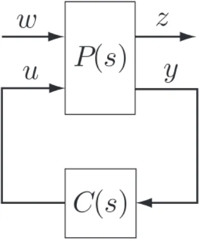
In order to obtain the parameterization of all robust stabilizing modified repetitive controllers, we must see that controllers C(s) hold (2.5). The problem of obtaining the controller C(s), which is not necessarily a modified repetitive controller, satisfying (2.5) is equivalent to the following H∞ control problem. In order to obtain the controller C(s) satisfying (2.5), we consider the control system shown in Figure 2.2.
P (s) is selected such that the transfer function from w to z in Figure 2.2 is equal to T (s)WT(s). The state space description of P (s) is, in general,
˙x(t) = Ax(t) +B1w(t) +B2u(t) z(t) = C1x(t) +D12u(t) y(t) = C2x(t) +D21w(t) , (2.10) where A ∈ Rn×n, B 1 ∈ Rn×m, B2 ∈ Rn×p, C1 ∈ Rm×n, C2 ∈ Rm×n, D12 ∈ Rm×p,
D21 ∈ Rm×m, x(t) ∈ Rn, w(t) ∈ Rm, z(t) ∈ Rm, u(t) ∈ Rp and y(t) ∈ Rm. P (s) is
called as the generalized plant. P (s) is assumed to satisfy the following assumptions [93]:
2.3. THE PARAMETERIZATION OF ALL ROBUST STABILIZING MODIFIED
REPETITIVE CONTROLLERS FOR MIMO PLANTS 29
w
z
u
P(s)
y
C(s)
Figure 2.2: Block diagram of H∞ control problem
1. (C2, A) is detectable, (A, B2) is stabilizable.
2. D12 has full column rank, and D21 has full row rank.
3. rank A− jωI B2 C1 D12 = n + p (∀ω ∈ R+) and 4. rank A− jωI B1 C2 D21 = n + m (∀ω ∈ R+).
Under these assumptions, according to [93], following lemma holds true.
Lemma 2.1. If controllers satisfying (2.5) exist, both
X ( A− B2D12† C1 ) + ( A− B2D12† C1 )T X +X { B1B1T − B2 ( D12T D12 )−1 B2T } X +(D12⊥C1 )T D12⊥C1 = 0 (2.11) and Y ( A− B1D21† C2 )T + ( A− B1D†21C2 ) Y +Y { C1TC1− C2T ( D21DT21 )−1 C2 } Y + B1D⊥21 ( B1D21⊥ )T = 0 (2.12)
have solutions X ≥ 0 and Y ≥ 0 such that
30
CHAPTER 2. ROBUST STABILIZING PROBLEM FOR MULTIPLE-INPUT/MULTIPLE-OUTPUT PLANTS and both A− B2D12† C1+ { B1B1T − B2 ( D12T D12 )−1 B2T } X (2.14) and A− B1D21† C2+ Y { C1TC1− C2T ( D21DT21 )−1 C2 } (2.15)
have no eigenvalue in the closed right half plane. Using X and Y , the parameterization of all controllers satisfying (2.5) is given by
C(s) = C11(s) + C12(s)Q(s)(I− C22(s)Q(s))−1C21(s), (2.16) where C11(s) C12(s) C21(s) C22(s) = Ac Bc1 Bc2 Cc1 Dc11 Dc12 Cc2 Dc21 Dc22 , (2.17) Ac = A + B1B1TX− B2 ( D12† C1+ E12−1B T 2X ) − (I − Y X)−1(B1D21† + Y C T 2E21−1 ) ( C2+ D21B1TX ) , Bc1 = (I− Y X)−1 ( B1D†21+ Y C T 2E21−1 ) , Bc2 = (I− Y X)−1 ( B2+ Y C1TD12 ) E12−1/2, Cc1 = −D†12C1− E12−1B T 2X, Cc2 = −E21−1/2 ( C2+ D21B1TX ) , Dc11 = 0, Dc12 = E12−1/2, Dc21 = E21−1/2, Dc22 = 0, E12= DT12D12, E21= D21DT21
2.3. THE PARAMETERIZATION OF ALL ROBUST STABILIZING MODIFIED
REPETITIVE CONTROLLERS FOR MIMO PLANTS 31
and Q(s) ∈ H∞ is any function satisfying ∥Q(s)∥∞ < 1. C(s) in (2.16) is written using Linear Fractional Transformation(LFT). Using homogeneous transformation,
(2.16) is rewritten by C(s) = ( Z11(s)Q(s) + Z12(s) )( Z21(s)Q(s) + Z22(s) )−1 = ( Q(s) ˜Z21(s) + ˜Z22(s) )−1( Q(s) ˜Z11(s) + ˜Z12(s) ) , (2.18)
where Zij(s)(i = 1, 2; j = 1, 2) and ˜Zij(s)(i = 1, 2; j = 1, 2) are defined by Z11(s) Z12(s) Z21(s) Z22(s) = C12(s)− C11(s)C21−1(s)C22(s) C11(s)C21−1(s) −C−1 21(s)C22(s) C21−1(s) (2.19) and Z˜11(s) Z˜12(s) ˜ Z21(s) Z˜22(s) = C21(s)− C22(s)C12−1(s)C11(s) C12−1(s)C11(s) −C22(s)C12−1(s) C12−1(s) (2.20) and satisfying Z˜22(s) Z˜12(s) ˜ Z21(s) Z˜11(s) Z11(s) −Z12(s) −Z21(s) Z22(s) = I = Z11(s) −Z12(s) −Z21(s) Z22(s) Z˜22(s) Z˜12(s) ˜ Z21(s) Z˜11(s) . (2.21)
Using Lemma 2.1, the parameterization of all robust stabilizing modified repetitive controllers for multiple-input/multiple-output plants is given by following theorem.
Theorem 2.1. If modified repetitive controllers satisfying (2.5) exist, both (2.11) and
(2.12) have solutions X ≥ 0 and Y ≥ 0 such that (2.13) and both (2.14) and (2.15)
have no eigenvalue in the closed right half plane. Using X and Y , the parameterization of all robust stabilizing modified repetitive controllers satisfying (2.5) is given by
C(s) = ( Z11(s)Q(s) + Z12(s) )( Z21(s)Q(s) + Z22(s) )−1 = ( Q(s) ˜Z21(s) + ˜Z22(s) )−1( Q(s) ˜Z11(s) + ˜Z12(s) ) , (2.22)
32
CHAPTER 2. ROBUST STABILIZING PROBLEM FOR MULTIPLE-INPUT/MULTIPLE-OUTPUT PLANTS
where Zij(s)(i = 1, 2; j = 1, 2) and ˜Zij(s)(i = 1, 2; j = 1, 2) are defined by (2.19)
and (2.20) and satisfying (2.21), Cij(s)(i = 1, 2; j = 1, 2) are given by (2.17) and
Q(s)∈ H∞p×p is any function satisfying ∥Q(s)∥∞< 1 and written by Q(s) = (Qn1(s) + Qn2(s)e−sT
) (
Qd1(s) + Qd2(s)e−sT )−1
, (2.23)
Qn1(s)∈ RH∞p×p, Qd1(s)∈ RH∞p×p, Qn1(s)∈ RH∞p×p and Qd2(s)∈ RH∞p×p are any functions satisfying ¯ σ{Z22(0) (Qd1(0) + Qd2(0)) + Z21(0) (Qn1(0) + Qn2(0))} = 0 (2.24) and rank (Qn2(s)− Qn1(s)Q−1d1(s)Qd2(s) ) = p. (2.25)
Proof. First, the necessity is shown. That is, if the robust stabilizing modified
repet-itive controller C(s) written by (2.7) stabilizes the control system in (2.1), then C(s) and Q(s) are written by (2.22) and (2.23), respectively. From Lemma 2.1, the pa-rameterization of all robust stabilizing controllers C(s) is written by (2.22), where
∥Q(s)∥∞ < 1. In order to prove the necessity, we will show that if C(s) written by (2.7) stabilizes the control system in (2.1), then Q(s) in (2.22) is written by (2.23). Substituting C(s) in (2.7) for (2.22), we have
Qn1(s) = N1n(s)N2d(s), (2.26)
Qn2(s) = N2n(s), (2.27)
Qd1(s) = D1n(s)D2d(s)N1d(s)N2d(s) (2.28)
and
2.3. THE PARAMETERIZATION OF ALL ROBUST STABILIZING MODIFIED
REPETITIVE CONTROLLERS FOR MIMO PLANTS 33
Here, N1n(s) ∈ RH∞p×p, N1d(s) ∈ RH∞p×p, N2n(s) ∈ RH∞p×p, N2d(s) ∈ RH∞p×p, D1n(s) ∈ RH∞p×p, D1d(s) ∈ RH∞p×p, D1n(s) ∈ RH∞p×p, D1d(s) ∈ RH∞p×p are coprime factors satisfying − ˜Z11(s) + ˜Z21(s)C1(s) = D1n(s)D−11d(s), (2.30) ( ˜ Z21(s)C2(s) + ˜Z11(s)q(s)− ˜Z21(s)C1(s)q(s) ) D1d(s) = D2n(s)D2d−1(s), (2.31) ( ˜ Z12(s)− ˜Z22(s)C1(s) ) D1d(s)D2d(s) = N1n(s)N1d−1(s) (2.32) and ( − ˜Z22(s)C2(s)− ˜Z12(s)q(s) + ˜Z22(s)C1(s)q(s) ) D1d(s)D2d(s)N1d(s) = N2n(s)N2d−1(s). (2.33)
From (2.26)∼(2.29), all of Qn1(s), Qn2(s), Qd1(s) and Qd2(s) are included in RH∞. Thus, we have shown that if C(s) written by (2.7) stabilize the control system in (2.1) robustly, Q(s) in (2.22) is written by (2.23). Since q(0) = I, from (2.26)∼(2.29) and (2.21), (2.24) holds true. In addition, from the assumption of rank C2(s) = p and
from (2.31) and (2.33),
rank D2n(s) = p (2.34)
and
rank N2n(s) = p (2.35)
hold true. From (2.34), (2.35), (2.27) and (2.29), (2.25) is satisfied. We have thus proved the necessity.
Next, the sufficiency is shown. That is, it is shown that if C(s) and Q(s) ∈ H∞ are settled by (2.22) and (2.23), respectively, then the controller C(s) is written by
34
CHAPTER 2. ROBUST STABILIZING PROBLEM FOR MULTIPLE-INPUT/MULTIPLE-OUTPUT PLANTS
the form in (2.7), q(0) = I and rank C2(s) = p hold true. Substituting (2.23) into
(2.22), we have (2.7), where, C1(s), C2(s) and q(s) are denoted by
C1(s) = (Z11(s)Qn1(s) + Z12(s)Qd1(s)) (Z21(s)Qn1(s) + Z22(s)Qd1(s))−1, (2.36) C2(s) = ( Qn1(s)Q−1d1(s) ˜Z21(s) + ˜Z22(s) )−1( Qn2(s)− Qn1(s)Q−1d1(s)Qd2(s) ) (Z21(s)Qn1(s) + Z22(s)Qd1(s))−1 (2.37) and q(s) =− (Z21(s)Qn2(s) + Z22(s)Qd2(s)) (Z21(s)Qn1(s) + Z22(s)Qd1(s))−1. (2.38) We find that if C(s) and Q(s) are settled by (2.22) and (2.23), respectively, then the controller C(s) is written by the form in (2.7). Substituting (2.24) into (2.38), we have q(0) = I. In addition, from (2.25) and (2.37),
rank C2(s) = p (2.39)
holds true.
We have thus proved Theorem 2.1
2.4
Control characteristics
In this section, we explain control characteristics of the control system in (2.1) us-ing the parameterization of all robust stabilizus-ing modified repetitive controllers for multiple-input/multiple-output plants. In addition, roles of Qn1(s), Qn2(s), Qd1(s) and Qd2(s) in (2.23) are clarified.
From Theorem 2.1, Q(s) in (2.23) must be included in H∞. Since Qn1(s)∈ RH∞ and Qn2(s) ∈ RH∞ in (2.23), if
(
Qd1(s) + Qd2(s)e−sT
)−1 ∈ H
∞, then Q(s) satisfies
Q(s)∈ H∞. That is, the role of Qd1(s) and Qd2(s) is to assure Q(s) ∈ H∞, and the role of Qn1(s) and Qn2(s) is to guarantee ∥Q(s)∥∞< 1.
2.4. CONTROL CHARACTERISTICS 35
Next, the input-output characteristic of the control system in (2.1) is shown. The transfer function S(s) from the periodic reference input r(s) to the error e(s) =
r(s)− y(s) of the control system in (2.1) is written by
S(s) = Sn(s)Sd−1(s), (2.40) where Sn(s) = C21−1(s) { I + (−C22(s)Qn2(s) + Qd2(s)) (−C22(s)Qn1(s) + Qd1(s))−1e−sT } (−C22(s)Qn1(s) + Qd1(s)) (2.41) and Sd(s) = Z21(s)Qn1(s) + Z22(s)Qd1(s) + (Z21(s)Qn2(s) + Z22(s)Qd2(s)) e−sT +G(s){Z11(s)Qn1(s) + Z12(s)Qd1(s) + (Z11(s)Qn2(s) + Z12(s)Qd2(s)) e−sT } . (2.42) From (2.19), (2.20) and (2.38), the low-pass filter can be represented as
q(s) =−C21−1(s) (−C22(s)Qn2(s) + Qd2(s)) (−C22(s)Qn1(s) + Qd1(s))−1C21(s),
(2.43) and the function Sn(s) is written by
Sn(s) = {
I− q(s)e−sT}C21−1(s) (−C22(s)Qn1(s) + Qd1(s)) (2.44) According to the (2.44) and (2.43), if Qn1(s), Qd1(s), Qn2(s) and Qd2(s) are selected satisfying (2.8), then ¯ σ { Sn(jωi) } ≤ ¯σ{I−q(jωi) } ¯ σ { C21−1(jωi) } ¯ σ { (−C22(jωi)Qn1(jωi) + Qd1(jωi)) } ≃ 0, (2.45) the output y(s) follows the periodic reference input r(s) with frequency components
ωi = 2π
36
CHAPTER 2. ROBUST STABILIZING PROBLEM FOR MULTIPLE-INPUT/MULTIPLE-OUTPUT PLANTS
with a small steady state error.
Next, the disturbance attenuation characteristic of the control system in (2.1) is shown. The transfer function from the disturbance d(s) to the output y(s) of the control system in (2.1) is written by (2.40). From (2.40), for ωi(i = 0, 1, . . . ,~) in (2.8) of the frequency component of the disturbance d(s) that is same as that of the periodic reference input r(s), if (2.45) holds, then the disturbance d(s) is attenuated effectively. This implies that the disturbance with same frequency component ωi(i = 0, 1, . . . ,~) of the periodic reference input r(s) is attenuated effectively. That is, the role of Qn2(s) and Qd2(s) is to specify the disturbance attenuation characteristic for the disturbance with same frequency component ωi(i = 0, 1, . . . ,~) of the periodic reference input
r(s). When the frequency components of disturbance d(s), ¯ωk(k = 0, 1,· · · , h), are not equal to ωi(i = 0, 1,· · · , ~), even if
¯
σ{I − q(j ¯ωk)} ≃ 0, (2.47)
the disturbance d(s) cannot be attenuated, because
e−j ¯ωkT ̸= 1 (2.48) and ¯ σ{I− q(j ¯ωk)e−j ¯ωkT } / ≃ 0. (2.49)
In order to attenuate the frequency components ¯ωk(k = 0, 1,· · · , h) of the disturbance
d(s), we need to satisfy
¯
σ{−C22(j ¯ωk)Qn1(j ¯ωk) + Qd1(j ¯ωk)} ≃ 0. (2.50)
This implies that the disturbance d(s) with frequency components ¯ωk ̸= ωi(i = 0, 1, . . . ,~, k = 0, 1, · · · , h) is attenuated effectively. That is, the role of Qn1(s) and
Qd1(s) is to specify disturbance attenuation characteristics for disturbance of frequen-cy ωd̸= ωi(i = 0, 1, . . . ,~).
From above discussion, the role of Qn2(s) and Qd2(s) is to specify the input-output characteristic for the periodic reference input r(s) and to specify for the disturbance