StarLITE: a new artificial landmark for the
navigation of mobile robots
Heesung Chae, Jaeyeong Lee, Wonpil Yu, and Nakju Lett Doh
Intelligent Robot Division, ETRI 161 Gajeong-dong, Yuseong-gu, Daejeon 305-350, South Korea {hschae; jylee; ywp}@etri.re.kr
Abstract ⎯ In this paper, we describe a new localization sensor
suite for the development of a location sensing network. The sensor suite comprises wirelessly controlled infrared beacons and an image sensor which detects the pixel positions of infrared sources. We describe the operating principles of the developed sensor suite and report the performance for mobile robot localization. The advantage of the developed sensor suite lies in its robustness and low cost to obtain localization information as well as simplicity of deployment to build a robotic location sensing network. Experimental results show that the developed sensor suite outperforms the state-of-the-art localization sensor.
Keywords ⎯ Localization, sensor network, mobile robot,
navigation.
1. Introduction
Navigation is the science of getting vehicles from place to place by determining the vehicle’s position, course, and distance traveled [1]. Prompt and relevantly accurate information about the vehicle’s position is a key component underpinning the success of a navigational application. In the field of mobile robotics, localization technology refers to a systematic approach to determine the current location of a mobile robot, namely, the 2-D position and heading angle of the mobile robot, by utilizing uncertain readings of robot sensors. Localization technology in the field of mobile robotics has been well studied and a multitude of methods have been proposed so far; a good overview on the robot localization technology can be found in [2].
Recently, with the advance of sensor and wireless connectivity technologies, it has become more feasible to design and build a wireless sensing network providing context-awareness; accordingly, there is an increasing need for accurate indoor location sensing in domestic, public, and military applications [3][4].
The most well-known location sensing technique using wireless communications may be GPS (Global Positioning System); GPS has dominated over all other outdoor radio navigation techniques because of its high accuracy, worldwide availability, and low cost [5]. For indoor location sensing applications, however, environmental effect imposes severe impediment to reliably obtain location information. Multi-path fading, interference, and non-LOS condition are well-known factors among others which make indoor localization a challenging task.
Triangulation techniques based on RSSI (Received Signal Strength Indicator), TOA (Time-Of-Arrival), AOA
(Angle-Of-Arrival), and TDOA (Time-Difference-Of-Arrival) are popular techniques to process radio signals to estimate location information. As mentioned earlier, the performance of these techniques is severely deteriorated depending on domain-specific RF factors or receiver-transmitter relative geometric configuration. On these grounds, in order to overcome the RF problems, even pattern-recognition approaches have been reported to model instantaneous spatial RF distribution inside a building [4][6]. More recently, ultra wideband (UWB) systems have attracted considerable attention to achieve accurate localization information [7][8]. Along with the wireless applications, researchers have paid attention to design intelligent systems which support a human or a robot inside building environment [9][10][11]. For this kind of space technology, knowledge about spatial information is critical for an intelligent space to be meaningful. For example, in order for a robot to move freely and intelligently inside such a space, very good information about the current location is necessary, as evidenced in the traditional robotics community [2]. For seamless provision of spatial information about a robot in a large space, cooperating networked sensors embedded in the space can be a plausible solution to this problem. We think that there is not yet a realistic solution for robotic tasks such as intelligent navigation, as can be appreciated from [12].
In this paper, we describe a localization sensor suite to build a location sensing network; the location sensing network will also be a constituting element to build a ubiquitous robotic space where a robot or human can have information assistance from the space or a specific robotic task can be carried out more efficiently compared with the traditional approaches. The minimal requirement of the proposed sensor suite for robot localization task comprises two infrared beacon modules attached on the ceiling of a space in question and an image sensor equipped on top of a mobile robot. This configuration is, in fact, very well recognized in robotics community [13][14][15]. But, there seems no rigorous consideration to use such a sensor suite to build a location sensing network in a large indoor environment.
This paper is organized as follows. In Section 2, we briefly introduce the design principles to build a location sensing network and describe how the proposed localization sensor suite satisfies the design constraints as well as its advantages. In Section 3, we describe the operating principles of the proposed sensor suite and report the robot localization performance based on the proposed sensor suite in Section 4.
Figure 1. Sensor configuration of the location sensing system
Finally, we conclude the paper and suggest future research directions in Section 5.
2. Development of a Location Sensing Network
In this section, we describe the design principles of a location sensing network as a key component for a ubiquitous robotic space. We introduce a couple of factors to build the location sensing network.z Accuracy: for a mobile robot to navigate reliably, the required accuracy should be less than 20 cm.
z Coverage: for a location sensing network to be meaningful, its coverage should be unlimited, which means that the location sensing network must be highly scalable.
z Availability: location information about a robot should be provided at any time of the day and any place of an indoor environment.
z Cost: constituting elements should be cost effective for a location sensing network to be deployed in a large indoor environment.
Although there are various other factors to be determined, we considered the four factors to play primary roles for building a location sensing network. As explained earlier, radio signal processing based on RSSI, TOA, or TDOA was excluded in an early stage due to its vulnerable characteristics according to RF interference or multi-path effects. Ultrasonic or vision sensors were also considered, but they were also turned out not to satisfy all of the constraints above.
We chose the proposed localization sensor suite as a basic element to infer location information. First of all, it is very cheap and by utilizing a wide-angle camera lens, the coverage provided by the localization sensor suite can be as large as up to 10 meters. More importantly, it is a well-established technology so that we could easily construct each network node. Finally, the robustness of location data as well as its accuracy is guaranteed under modest environmental conditions. In the next section, we describe the developed localization sensor suite in more detail.
Figure 2. Two sample images of a pair of infrared beacons. The top image was captured without filter and the bottom with an infrared
band-pass filter.
3. Self-Localization with the Proposed Sensor Suit
The location sensing system using the proposed sensor suite is configured such that infrared beacon modules are attached on the ceiling of a space in question and an image sensor is mounted on top of a mobile robot as shown in Fig. 1. The image sensor is a CCD camera having an infrared band-pass filter. It is oriented to look upward so that its optical axis is perpendicular to the ground. For the sake of maximal field of view, a wide-angle camera lens is utilized. Each beacon module contains an infrared LED which on and off status is controlled externally by wireless communication. In order to control LEDs of the beacons independently, a unique beacon ID is assigned to each infrared beacon module.The location information of a robot can be obtained when at least two infrared LEDs are detected within the field of view of the camera. Therefore, more than two beacons may be required to cover the whole area of the space in a large indoor environment. The necessary number of infrared beacons varies according to the 2-D geometry of the space, the height of the ceiling, and the angle of the camera field of view. The optimal disposition of infrared beacons is out of scope of this paper and will not be further described.
The localization is performed in two steps. In first step the image coordinates of the infrared LEDs, if any, are computed and tag IDs are then identified. In second step 2-D location and heading angle of a robot are computed from the image coordinates and world coordinates of the detected LEDs.
The infrared band-pass filter attached on the CCD camera transmits only infrared band by filtering out visible band. Figure 2 demonstrates the effect of infrared band-pass filtering. The top image was captured with a normal CCD camera and the bottom one captured with the same camera but equipped an infrared band-pass filter. The infrared LEDs are well discriminated as white spots in the bottom image. As well known in vision community, it is very difficult to robustly locate particular patterns from images in varying illumination condition. Our infrared band-pass filtering solution makes the detection problem a simple thresholding one, and more importantly, it enables robust detection of target beacons at any time of the day.
Let be an image, from which infrared spots to be detected. Firstly, the image is binarized by fixed thresholding with a predetermined threshold value. The target blobs of infrared spots are then located by connected component analysis. Let be the kth blob located, for k = 1, …, n. Finally, the mass center of each blob, , is given by
) , (x y I k b ) , (xk yk
∑
∈ = k b y x k xI x y x ) , ( ) , ( (1)∑
∈ = k b y x k yI x y y ) , ( ) , ( , (2) for k = 1, …, n.In order to identify the emitting source of the detected LED spot, only one infrared LED is turned on and the others turned off before capturing the image. If any spot is detected from the image, it is identified as being originated from the beacon which was set to be turned on. This detection and identification procedure is iterated for each beacon module until two spots are detected.
3.2 Computation of 2-D Location and Heading Angle
For the description of robot localization procedure, we use three coordinate systems of world coordinate system,
image coordinate system, and extra coordinate system,
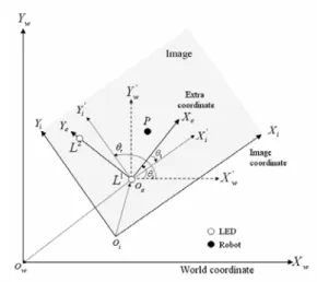
denoted by subscript w, i, and e respectively. Figure 3 shows the relationship of the three coordinate systems. The world coordinate represents the real position in the space in question and the image coordinate refers to the pixel coordinate in the image. The extra coordinate system is a beacon-oriented coordinate system and introduced for convenience in transformation form image coordinate to world coordinate.
In the previous step, we have located two LEDs in the image and determined their corresponding beacon IDs. Let L1i
and L2i be the image coordinates of the detected two LEDs and
let L1w and L2w be the corresponding world coordinates. We
assume that the world coordinate of each beacon is already known. The extra coordinate system is constructed from L1i
and L2i so that L1i becomes the origin and y-axis spans from L1i
to L2i as shown in Fig. 3. Let Pi be the image coordinate of a
robot. Then we can set Pi to be the center of image since the
camera is mounted on top of a robot vertically to the ground. The localization task is to compute the world coordinate of the robot, denoted by Pw, and heading angle, denoted by .
This requires two times of coordinate transformation, firstly from image coordinate to extra coordinate and then from extra
r
θ
Figure 3. Three coordinate systems used in roblot localization.
coordinate to world coordinate. Let be the rotation angle between x-axes of image and extra coordination systems. The extra coordinate of the robot, denoted by P
1 θ e, is then given by ) ( i ie ie e R P T P = ⋅ − ,
where Tie is a translation matrix and Rie is a rotation matrix,
given by ⎥ ⎦ ⎤ ⎢ ⎣ ⎡ − − − − − = ) cos( ) sin( ) sin( ) cos( 1 1 1 1 θ θ θ θ ie R , (3) i ie L T = 1. (4)
We define a scale factor, s, to unify the metrics of extra coordinate system and world coordinate system, which is given by || || || || 2 1 2 1 i i w w L L L L s − − = , (5)
where function ||⋅|| denotes the L2 - norm. The world coordinate
of the robot, Pw, is then given by
we e we w R sP T P = −1⋅ + (6) ⎥ ⎦ ⎤ ⎢ ⎣ ⎡ − = ⎥ ⎦ ⎤ ⎢ ⎣ ⎡ − − − − − = − − ) cos( ) sin( ) sin( ) cos( ) cos( ) sin( ) sin( ) cos( 2 2 2 2 1 2 2 2 2 1 θ θ θ θ θ θ θ θ we R (7) w we L T = 1 , (8)
where be the rotation angle between x-axes of world and extra coordination systems.
2
θ
The heading angle of the robot, θ , can be simply r calculated as 2 1 2 π θ θ θr = − + . (9)
The computed Pw and θ give the final location information of r
the robot.
3.2 Measuring the tag’s position on the image coordinate system
4. Experimental Result
For evaluation of localization performance of the proposed sensor suite, we have conducted an experiment by changing the location and heading angle of a cart mobile robot. The
Figure 4. Localization results with the proposed sensor suit. experiment was performed in an indoor environment where three infrared beacon modules are attached on the ceiling. Each distance between infrared beacons is 120cm. The image sensor used is a CCD board camera having 1.9mm fisheye lens. The location information was computed for every grid points which are spaced regularly with 60cm distance. Figure 4 shows the localization results using the proposed sensor suit. The estimated positions are represented by circle and true positions with asterisk. The mean position error is 4.1cm with standard deviation of 2.9cm. We have the maximum position error of 17.1 cm at (180, 60) because of uneven ground condition. The experiment result shows that the proposed sensor suit gives acceptable localization performance in indoor environment.
5. Conclusion
In this paper, we have proposed a localization sensor suite for development of robotic location sensing network. The proposed sensor can operate not depending on illumination condition, which is not the case for most vision-based approaches. Experimental result confirms the robustness of location data and its accuracy. Future work is to consider combination method with other localization technique to minimize required infrared beacon modules and for error recovery.
ACKNOWLEDGEMENT
This work was supported by Ministry of Information and Communication, Korea.
REFERENCES
[1] I. J. Cox and G. T. Wilfong, Autonomous Robot Vehicles, Springer-Verlag, 1990.
[2] J. Borenstein, H. R. Everett, and L. Feng, “Where am I? Sensors and Methods for Mobile Robot Positioning,” Technical Report, Univ. of Michigan, APR. 1996.
[3] Fuji-Keizai USA, Inc., “Wireless Sensing Networks: Market, R&D and Commercialization Activities,” Market Research Report, FEB. 2004. [4] K. Pahlavan, X. Li, and J. Makela, “Indoor Geolocation Science and
Technology,” IEEE Communications Magazine, pp. 112-118, FEB. 2002.
[5] T. S. Rappaport, J. H. Reed, and B. D. Woerner, “Position Location Using Wireless Communications on Highways of the Future,” IEEE Communications Magazine, pp. 33-41, OCT. 1996.
[6] K. Yamano, K et al., “Self-localization of mobile robots with RFID system by using support vector machine,” IEEE Int. Cont. Intell. Robots and Systems, pp. 3756-3761, 2004.
[7] J. Y. Lee and R. A. Scholtz, “Ranging in a Dense Multipath Environment Using an UWB Radio Link,” IEEE J. Selected Areas in Communications, vol. 20, no. 9, DEC. 2002.
[8] The Ubisense Smart Space Platform, http://www.ubisense.net.
[9] J. H. Lee, K. Morioka, N. Ando, H. Hashimoto, “Cooperation of Distributed Intelligent Sensors in Intelligent Environment,” IEEE/ASME Trans. Mechatronics, vol. 9, no. 3, SEP. 2004.
[10] N. Y. Chong, H. Hongu, K. Ohba, S. Hirai, and K. Tanie, “A Distributed Knowledge Network for Real World Robot Applications,” IEEE Int. Conf. Intell. Robots and Systems, pp. 187-192, 2004.
[11] D. Haehnel, W. Burgard, D. Fox, K. P. Fishkin, M. Philipose, “Mapping and Localization with RFID Technology,” IEEE Int. Conf. Robotics and Automation, pp. 1015-1020, 2004.
[12] J. Hightower and G. Borriello, “Location Systems for Ubiquitous Computing,” IEEE Computer, vol. 34, no. 8, pp. 57-66, AUG. 2001. [13] W. Lin, S. Jia, T. Abe, and K. Takase, “Localization of Mobile Robot
based on ID Tag and WEB camera,” IEEE Int. Conf. Robotics and Mechatronics, pp. 851-856, 2004.
[14] Y. Nagumo and A. Ohya, “Human Following Behavior of an Autonomous Mobile Robot Using Light-Emitting Device,” IEEE Int. Workshop on Robot and Human Interaction, pp. 18-21, 2001.
[15] J. S. Park and M. J. Chung, “Path Planning with Uncalibrated Stereo Rig for Image-based Visual Servoing under Large Pose Discrepancy,” IEEE Trans. Robotics and Automation, vol. 19, no. 2, pp. 250-258, APR. 2003.