Japan Advanced Institute of Science and Technology
JAIST Repository
https://dspace.jaist.ac.jp/Title
An Integrated 2D and 3D Location Measurement
System Using Spiral Motion Positioner
Author(s)
Lee, Geunho; Noguchi, Naoto; Kawasaki, Nobuya;
Chong, Nak Young
Citation
2012 IEEE International Conference on Robotics
and Automation (ICRA): 4422-4427
Issue Date
2012-05
Type
Conference Paper
Text version
author
URL
http://hdl.handle.net/10119/10614
Rights
This is the author's version of the work.
Copyright (C) 2012 IEEE. 2012 IEEE International
Conference on Robotics and Automation (ICRA),
2012, 4422-4427. Personal use of this material is
permitted. Permission from IEEE must be obtained
for all other uses, in any current or future
media, including reprinting/republishing this
material for advertising or promotional purposes,
creating new collective works, for resale or
redistribution to servers or lists, or reuse of
any copyrighted component of this work in other
works.
An Integrated 2D and 3D Location Measurement System Using Spiral
Motion Positioner
Geunho Lee, Naoto Noguchi, Nobuya Kawasaki, and Nak Young Chong
Abstract— In this paper, we describe the design and imple-mentation of an integrated two dimensional and three dimen-sional location measurement system, where different types of range sensors can be mounted onto the spiral motion positioner. The proposed sensor/positioner system enables terrestrial and aerial robots to observe their surroundings in all directions without blind spots. Using a nut-and-bolt and link mechanism, the proposed positioner driven by a single stepper motor exhibits continuous three dimensional spiral trajectories over the upper hemisphere. This single axis motor driven system helps decrease the size, weight, and structural complexity of the system. Particular attention in this work is placed on how to effectively combine two dimensional and three dimensional measurement functions. We verify the validity and effective-ness of the proposed location measurement system through simulations and experiments. It is expected that the proposed system can be incorporated into a wide range of mobile robot platforms.
I. INTRODUCTION
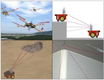
Advances in technology and manufacturing have created various types of location measurement systems that can be used for robotics, security and surveillance systems, and so on. Most existing sensors have been designed to measure the distance in the same flat plane. However, current robot appli-cations are expanding rapidly from the flat surface to a wide range of terrestrial, airborne, and undersea environments. Re-cently, much attention has been paid to developing different types of mobile robots such as flying robot [1], swimming robot [2], or jumping robot [3] that can operate in large three dimensional environments. Therefore, the objective of this paper is to develop a cost effective and energy efficient three dimensional location measurement system that can be incorporated into a wide range of mobile robot platforms in the areas of distributed robotics and security and surveillance as shown in Fig. 1.
There have been considerable efforts to secure wide-ranging observations for two dimensional applications. A commonly used approach was to have larger numbers of sensors installed around the circumference of a robot (e.g., sonar rings of Mobilerobots Pioneer P3-DX [4] or infrared sensor array [5]). Alternatively, a sensor system capable of rotating around a vertical axis was designed (e.g., Hokuyo scanning laser range finder (LRF) [6]). We have also de-veloped an infrared proximity sensor that provides full 360 degree coverage with variable rotation angle and speed [7].
G. Lee, N. Noguchi, N. Kawasaki, and N. Y. Chong are with the School of Information Science, Japan Advanced Institute of Science and Tech-nology, Ishikawa, Japan {geun-lee, n-noguchi cbr250rr, nobuya k, nakyoung}@jaist.ac.jp
Fig. 1. 3D range sensor application scenarios
Three dimensional location measurement systems have been implemented in different ways such as pan-and-tilt positioner and Laser Radar (LADAR). The pan and tilt mechanism enables sensor beams to sweep up and down and to the left and right at various angles by generating two independent rotation motions with respect to a vertical axis and a horizontal axis, respectively. A wide range of sensors mounted onto the pan and tilt positioner has been applied to surveillance [8], SLAM [9], grasping [10], and robotic eye mechanism [11]. However, the overall system tends to become heavy and bulky. Similarly, three dimensional laser scanners have been recently proposed by combining a tilting motion and Hokuyo LRF [12]-[14], or by placing two SICK LMS 200 LRFs in mutually perpendicular directions [15]. However, several questions remain as to how the difference between latitude and longitude resolutions and substantial blind spots can be resolved. On the other hand, LADAR employs the same operation principle like radars and light from laser beams [16]. Through analysis of the pulsed laser light reflected from objects, LADAR can obtain the positions, velocities, and other geometric features of objects. Due to its capability to observe large spaces with very high precision, LADAR has a large number of applications in geography and atmospheric physics, industrial systems, and robotics [17]-[21]. However, LADAR turns out to be a very complicated system, as it needs additional optical components such as mirror, photo-detector, and receiver electronics.
In the most fundamental sense, one simple and easy-to-implement idea for three dimensional sensing is to mount existing sensors developed for two dimensional applications
rotation device motor drive gantry part function device stud bolt dimension selector flange nut crank Joint-1 Joint-2 flange ball bearing link rod Joint-3 Gear-1 base board Gear-2 stepper motor motor container
Fig. 2. Mechanical structure of 3D positioner TABLE I
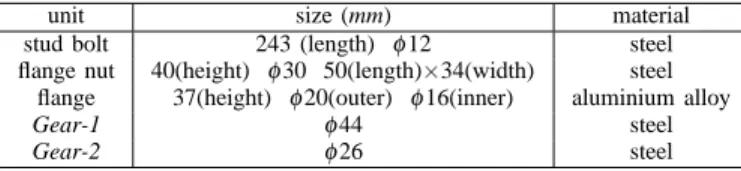
MECHANICAL SPECIFICATION OF IMPORTANT COMPONENTS
unit size (mm) material
stud bolt 243 (length) φ12 steel flange nut 40(height) φ30 50(length)×34(width) steel
flange 37(height) φ20(outer) φ16(inner) aluminium alloy
Gear-1 φ44 steel
Gear-2 φ26 steel
onto a three dimensional positioner. Along the lines of this idea, this paper presents a novel three dimensional positioner enabling two dimensional range sensors to measure the distance to objects in all directions without blind spots. The main features of the positioner are summarized as follows: 1) a simple nut-and-bolt and link mechanism; 2) continuous spiral trajectories; and 3) a single motor driven system that helps reduce the size, weight, mechanical complexity, and cost. Moreover, we effectively integrate two dimensional and three dimensional positioning functions in this work.
II. PROTOTYPE DEVELOPMENT
A. Mechanical Design
Fig. 2 shows the schematic view of the proposed three dimensional positioner that consists of the following four components: motor drive, gantry, rotation device, and func-tion device. The motor drive includes one Tamagawa Seiki SP5423-2AA0 stepper motor, a motor driver, and a gear. The gantry part consists of a motor container and a stud bolt with a 4 mm pitch. The rotation device includes a crank, a link rod, a base board, a flange, a ball bearing, and a gear from the top down to the bottom. The crank, the link rod, and the base board are fabricated using Nippon Polypenco MC901 MC nylon. The function device is composed of the dimension selector made from the same MC nylon and a flange nut. Detailed specifications of key components are summarized in Table I.
Specifically, the motor drive generates the rotation motion of 0.72 degree per one motor step. The gantry part is to
flange ball bearing Gear-1 Gear-2 stud bolt flange nut motor container
Fig. 3. Assembly details between the rotation device and the stud bolt
support the superstructure of the positioner. Through
Gear-1, the rotation by the motor is transmitted to the flange. As
the base board fastened to the flange rotates, the function device connected through Joint-1 triggers the same motion. Various types of sensors can be mounted onto the distal end of the rotation device. The function device represents a spiral pattern according to the thread of the stud bolt. It should be emphasized that the dimension selector determines either two or three dimensional range observations that will be explained in the next section.
As illustrated in Fig. 3, we install the stud bolt into a threaded hole located on the center of the motor container bottom surface. The rotation device and function device are then successively screwed into the bolt. Joint-1 connects the dimension selector of the function device with the crank of the rotation device. In the rotation device, 2 and
Joint-3 at each end of the link rod are joined with the crank and
the base board, respectively. The flange is attached to the bottom of the base board. As we bore a hole with the same dimension of the ball bearing into the top surface of the motor container, the bearing can be housed in the surface, and Gear-1 is located underneath the bearing. Moreover, we force Gear-1 and Gear-2 to interlock smoothly. Practically, in our current prototype, the reduction ratio between the gears is set to 1 : 2.86. Finally, Fig. 4-(a) shows the snapshots of the prototype. The dimension of the prototype is presented in Fig. 4-(b), where the red dashed circle indicates a radius of gyration required when the rotation device rotates.
B. Spiral Motion Control
Fig. 5 illustrates the overall control schematic. The Atmel AVR ATmega328P microcontroller is used to control rotation motions by the stepper motor and to feed measured data to an outside component through a communication link (e.g., RS-232C). Here, the measured data is two-fold. One is the motor feedback data, and the other is the sensor measurement data. Meanwhile, the controller forwards the control signals of both the step and direction to the motor driver. The direction signal sets the direction of rotation and each pulse on the step signal causes the controller to rotate the motor one step in that direction. The rotor position of the motor is fed to the controller.
(a) assembled 3D positioner 2 40 m m 70 m m 120 mm 60 mm radius of gyration
a
r
a
r
b
r
b
r
(b) dimensions of 3D positioner Fig. 4. 3D positioner prototypeFig. 5. Overall control schematic
We now explain how the rotation by the stepper motor allows the proposed positioner to exhibit spiral motions. Ac-cording to the step and direction command of the controller, the motor rotates. Then, the base board rotates an angle determined by the gear reduction between 1 and
Gear-2, and the crank moves up and down while rotating. Since
the crank is directly connected with the flange nut, it ascends or descends along the thread of the stud bolt according to the vertical location of the flange nut, resulting in spiral motions. Simultaneously, the flange nut hanging from the bolt rotates.
III. OPERATION CONTROL FUNCTIONS
A. 3D Observation Operation
As mentioned in the previous section, the motion of the crank in the positioner represents a spiral pattern along the thread of the stud bolt. To apply the spiral motion to
(a) ascending while rotating clockwise
(b) descending while rotating counterclockwise
Fig. 6. Ascending and descending motions of the crank in the positioner
three dimensional observations, we define the following two specific points located on the bolt: the starting and the turning points. The starting point psindicates the lower limit for the crank’s descent and its initial position. On the other hand, the turning point pt is the upper limit for its ascent. If the positioner operates continuously, it ascends from ps until it reaches pt. Once the positioner reaches pt, it starts to descend toward ps. By doing each of the above processes, it repetitively moves between ps to pt until the stop signal is transmitted from the controller (see Fig. 5). For this, two Switronic SSM-001 and SSM-003 micro switches are utilized to set two points, and two switches are mounted on the based board and the stud bolt, respectively.
Fig. 6 illustrates ascending and descending motions of the crank. The black arrows at the crank are the sensor (beam) pointing direction at each instant. When the crank ascends from ps while rotating with a spiral pattern, the positioner enables the sensor on the crank to cover hemispheric ranges where the crank positioned at pt is the zenith of the hemi-sphere (see Fig. 7-(a)). Similarly, when the crank descends from pt, the positioner also obtains the same hemispheric coverage. Consequently, if two positioners are located at the upper and lower sides, respectively, a combined spheral coverage can be obtained as shown in Fig. 7-(b).
Moreover, when the crank ascends and descends,
Joint-1 and Joint-2 rotate in the same directions (see Fig. 6).
However, Joint-3 changes the rotation direction when the crank becomes the radius of gyration as shown in Fig. 4-(b). Even though these joints are all passive types, the rotation direction can be controlled according to the length of the link rod that can be adjusted to control the coverage range
(a) hemispheric coverage (b) combined spheral coverage Fig. 7. Illustration of 3D sensor coverage range
of the positioner.
B. Transformation between 2D and 3D Observation
Specific ranges of data required will vary according to the task and arena. Therefore, we need to develop a more efficient sensing approach desirable under certain conditions. To this end, we devised a mechanical unit capable of transforming sensing ranges from 3D to 2D and vice versa. It is necessary to make a few slight modification to the basic 3D positioner design, as will be explained below.
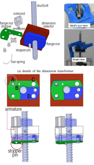
Fig. 8-(a) illustrates the details of an additional unit, enabling the positioner to select either 2D or 3D operation. The proposed dimension transformer comprises a Maruha Electric MD-282 solenoid and armature, a flange nut stopper, a stopper pin, three rivet pins, and a bar spring. The solenoid is mounted on the dimension selector, and the flange nut stopper is mounted underneath the flange nut. When the solenoid turns off, its armature is connected to the stopper pin as illustrated in Fig. 8-(b). At the point A, the stopper pin passing through the flange nut slightly protrudes from the flange nut stopper. Both ends of the bar spring are fixed at the point B and the point D through the point C where
B and D indicate different contact surfaces. This is the 3D
operation mode illustrated in Fig. 8-(b).
By the time the positioner controller controls on signal (see Fig. 5), the solenoid turns on electrically and pulls its armature. As illustrated in Fig. 8-(c), there is a gap between the armature and the stopper pin. Then, the flange nut stopper by the elastic force of the bar spring rotates slightly and the stopper pin is sucked into the side of the armature. Consequently, the rotation from the crank is blocked since there is no joint between the dimension selector and the flange nut. In other words, the rotation is not transmitted to the flange nut through the dimension selector as illustrated in Fig. 8-(c). This is the mode of 2D operation. Conversely, if the solenoid turns off, the stopper pin returns to the 3D operation mode by pushing the armature.
IV. EXPERIMENTAL RESULTSANDDISCUSSION
To demonstrate the validity and effectiveness of the pro-posed 3D sensor positioner, this section discusses some results of simulation and experiments. We performed simula-tions to examine how the positioner generates desired spiral
(a) details of the dimension transformer
(b) selection of 3D mode (c) selection of 2D mode Fig. 8. Operation dimension transformer between 2D and 3D
motions, and how all the possible combinations of individual parts affect the effective sensing range. The dynamic simula-tion model of the posisimula-tioner is created with SolidWorks [22] and incorporated into a well-known multi-body dynamics analysis software RecurDyn [23].
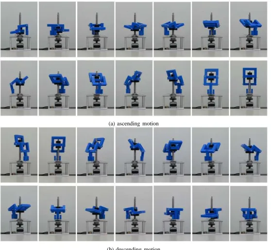
First, Fig. 9 shows continuous snapshots for the ascending and descending motions of the prototype. We could observed that the positioner generates desired spiral motions from the start point to the target point. As presented in our video clip, the positioner also operates the ascending and the descending motions according to the starting and turning points realized by the micro switches. It is also confirmed that the overall integration of the positioner system and its controller can be considered quite satisfactory for continuous observation operations.
Next, we check whether the proposed 3D positioner pro-vides uniform hemispheric coverage while exhibiting contin-uous spiral trajectories. An imaginary sensor beam trajectory is shown in Fig. 10. The spiral-in and spiral-out trajectories are clearly seen in the figure, which depends on the height of the crank on the stud bolt. From the result, we can
(a) ascending motion
(b) descending motion
Fig. 9. Continuous snapshots for 3D operations (from the upper left to the lower right)
confirm that the positioner performs a continuous motion that allows sensor beams to scan the surface area of the upper hemisphere.
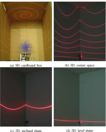
To examine the positioner’s motion accuracy according to different operation modes, 3D, 2D, and transformation between 2D and 3D functions were tested. To visualize the positioner trajectory, a laser beam sensor was mounted on the crank as illustrated in Fig. 6. Experiments were performed in a cardboard box and a corner space. Experiment results for 3D and 2D functions are shown in Fig. 11, obtained by performing high-speed photography. Figs. 11-(a) and (b) clearly show that the positioner provides a hemispheric coverage while rotating with a spiral pattern. Figs. 11-(c) and (d) present the 2D observation data for different planes. Consequently, the proposed positioner can provide robots with an efficient, fully adaptive sensing scheme. We should emphasize that these various positioner functions were realized through a single motor.
V. CONCLUSIONS
This paper presented a new 3D positioner enabling ex-isting 2D range sensors to measure the distance to objects in all directions without blind spots. The main features of the proposed positioner could be summarized as follows: 1) a simple nut-and-bolt and link mechanism; 2) continuous
spiral trajectories over the upper hemisphere; and 3) a single motor driven system. Furthermore, an integrated 2D and 3D operation functions was also demonstrated through simulations and experiments successfully. From the results so far, we have confirmed that the proposed positioner can be cost-effectively applied to mobile robots for 3D exploration and surveillance missions. As our future studies, we will perform the design optimization of link length in order to minimize the positioner size while providing desired sensor beam coverage. We will then develop recognition algorithms for different sensors corresponding to the positioner trajec-tory, and install the sensor positioner system into a mobile robot platform to evaluate their performance in real-world conditions.
REFERENCES
[1] D. Gurdan, J. Stumpf, M. Achtelik, K.-M. Doth, G. Hirzinger, and D. Rus, “Energy-efficient autonomous four-rotor flying robot controlled at 1 kHz,” Proc. IEEE Int. Conf. Robotics and Automation, pp.361-366, 2007
[2] N. Kato, “Control performance in the horizontal plane of a fish robot with mechanical pectoral fins,” IEEE Journal of Oceanic Engineering, vol.25, no.1, pp.121-129, 2000
[3] U. Scarfogliero, C. Stefanini, and P. Dario, “Design and development of the long-jumping ‘Grillo’ mini robot,” Proc. IEEE Int. Conf.
Robotics and Automation, pp.467-472, 2007
(a) front view
(b) floor plan
Fig. 10. 3D sensor beam trajectory: simulations
[5] J. Pugh, X. Raemy, C. Favre, R. Falconi, and A. Martinoli, “A fast on-board relative positioning module for multi-robot systems,”
IEEE/ASME Trans. Mechatronics, vol.14, no.2, pp.151-162, 2009
[6] http://www.hokuyo-aut.jp/02sensor/
[7] G. Lee and N. Y. Chong, “Low-cost dual rotating infrared sensor for mobile robot swarm applications,” IEEE Trans. Industrial Informatics, vol.7, no.2, pp.277-286, 2011
[8] Y. Xu and D. Song, “Systems and algorithms for autonomous and scalable crowd surveillance using robotic PTZ cameras assisted by a wide-angle camera,” Autonomous Robots, vol.29, no.1, pp.53-66, 2010 [9] P. Jensfelt, S. Ekvall, D. Kragic and D. Aarno, “Integrating active mobile robot object recognition and SLAM in natural environments,”
Proc. IEEE Int. Conf. Intelligent Robots and Systems, pp.5792-5797,
2006
[10] A. Saxena, L. Wong, M. Quigley, and A. Y. Ng, “A vision-based system for grasping novel objects in cluttered environments,” Int.
Journal of Robotics Research, vol.27, no.2, pp.157-173, 2008
[11] R. Beira, M. Lopes, M. Praga, J. Santos-Victor, A. Bernardino, G. Metta, F. Becchi, and R. Saltaren, “Design of the robot-cub (iCub) head,” Proc. IEEE Int. Conf. Robotics and Automation, pp.94-100, 2006
[12] T. Yoshida, K. Irie, E. Koyanagi and M. Tomono, “3D Laser Scanner with Gazing Ability,” Proc. IEEE Int. Conf. Robotics and Automation, pp.3098-3103, 2011
[13] J. Morales, J. L. Martinez, A. Mandow, A. Pequeno-Boter, and A. Garcia-Cerezo, “Design and Development of a Fast and Precise Low-Cost 3D Laser Rangefinder,” Proc. 2008 IEEE Int. Conf. Mechatronics, pp.621-626, 2011
[14] K. Ohno, T. Kawahara, and S. Tadokoro, “Development of 3D laser scanner for measuring uniform and dense 3D shapes of static objects
(a) 3D: cardboard box (b) 3D: corner space
(c) 2D: inclined plane (d) 2D: level plane Fig. 11. 3D and 2D sensor beam trajectory: experiments
in dynamic environment,” Proc. 2008 IEEE Int. Conf. Robotics and
Biomimetics, pp.2161-2167, 2009
[15] S. Iwashina, A. Yamashita and T. Kaneko, “3-D map building in dynamic environments by a mobile robot equipped with two laser range finders,” Proc. 3rd Asia Int. Sym. Mechatronics, pp.1-5, 2008 [16] M. E. O’Brien and D. G. Fouche, “Simulation of 3D laser radar
systems,” Lincoln Laboratory Journal, vol.15, no.1, pp.37-60, 2005 [17] O. Naroditsky, A. Patterson IV, and K. Daniilidis, “Automatic
align-ment of a camera with a line scan LIDAR system,” Proc. IEEE Int.
Conf. Robotics and Automation, pp.3429-3434, 2011
[18] X. Yuan, C.-X. Zhao and Z.-M. Tang, “LIDAR scan-matching for mobile robot localization,” Information Technology Journal, vol.9, no.1, pp.27-33, 2010
[19] A. Desai and D. Huber, “Objective evaluation of scanning ladar configurations for mobile robots,” Proc. IEEE/RSJ Int. Conf. Intelligent
Robots and Systems, pp.2182-2189, 2009
[20] A. Nuchter, K. Lingemann, J. Hertzberg, and H. Surmann, “6D SLAM-3D mapping outdoor environments,” Journal of Field Robotics, vol.24, no.8-9, pp.699-722, 2007
[21] K. M. Nickels, A. Castano, and C. Cianci, “Fusion of LIDAR and stereo range for mobile robots,” Proc. 11th Int. Conf. Advanced
Robotics, pp.65-70, 2003
[22] Solidworks User’s Manual, http://www.solidworks.co.jp [23] Recurdyn User’s Manual, http://www.functionbay.co.jp