Study of A Computer-based Emergency
Operating Procedure with Desirable Features for Human Operators of Nuclear Power Plants
2018, September
Tulis Jojok Suryono
Graduate School of Natural Science and Technology (Doctor’s Course)
OKAYAMA UNIVERSITY
Abstract
Operating procedures are guidance for operators to monitor, make decision and take related counter actions in normal, abnormal and emergency conditions of nuclear power plants. The initial form of operating procedures, paper-based procedures (PBPs), have some drawbacks such as high operators’ workload and necessity of much time to find and execute procedures related to the events. Therefore, because of the development of computer and information technology, computer-based procedures (CBPs) were developed to overcome the problems. CBPs provide more benefits, such as dynamic information representation, providing navigational links to other necessary procedures, providing path tracking in the procedure and providing supplementary information related to the procedure.
In emergency condition, after identifying the accident based on the symptoms and anomalies in the plant, operators should take appropriate actions following the instructions in the emergency operating procedures (CBPs). Such counteractions, indicated by the change of states of components, consequently affect other plant components and also the plant behavior. The information (components influenced and future plant behavior) is important and useful for operators to help them to predict and anticipate the future condition of the plant. However, most of CBPs do not provide this additional information. The lack of this information will decrease the situation awareness of operators. In addition, in the era of resilience, operators are expected to have the ability to anticipate the future condition of the plant. Therefore, the thesis discusses the additional information as the desirable features for CBPs to increase the situation awareness of operators and to achieve resilience system.
MFM as a functional modeling is used to investigate how to derive the additional information. The counter actions are modeled by the control function of MFM, which is used to change the state of a function primitive of MFM model of PWR plant based on an operation knowledge described in the EOP of SGTR accident. The thesis also discusses the technique to derive the additional information using algorithm based on causal effect relation and influence propagation. The information is presented in the form of explanation sentences which is understandable by human operators. The information is displayed on the CBP user interface each time an operator selects a specified procedure step.
ii Acknowledgments
Firstly, I would like to express my sincere gratitude to my advisor Prof. Akio Gofuku for the continuous support of my PhD study and related research, for his patience, motivation, and immense knowledge. His guidance helped me in all the time of research and writing of this thesis. I could not have imagined having a better advisor and mentor for my PhD study.
I would like to convey my gratitude to Ministry of Research, Technology and Higher Education for granting scholarship Program for Research and Innovation in Science and Technologies (RISET-Pro) grant number 8245-ID for the completion of my doctoral studies. I would also like to acknowledge JSPS KAKENHI Grant Number 16H03136 which was partially supported my research activities.
I would like to thank Dr. Tetsushi Kamegawa and Dr. Taro Sugihara for the constructive comments in the interim presentation in our laboratory and also lab members for supporting my research activities in the laboratory. I would like also to thank my friends who always support during my life in Okayama in the past years.
Finally, most importantly, I would like to thank my parents, my lovely wife and my two daughters for the moral support and the prayer.
iii Contents
Abstract ... i
Acknowledgments ... ii
Contents ... iii
List of Figures ... v
List of Tables ... vii
1. Introduction ... 1
1.1. Background ... 1
1.2. Research theme ... 2
1.3. Thesis structures ... 4
2. Literature Review ... 5
2.1. Computer-based Procedures ... 5
2.1.1. Overview of Operating Procedures ... 5
2.1.2. Computer-based Emergency Operating Procedures ... 7
2.2. Operator Support Systems ... 11
2.3. Situation Awareness ... 15
2.4. Resilience Engineering ... 20
2.5. Functional Information ... 24
3. Techniques to Derive the Additional Information Based on MFM Models ... 27
3.1. Overview of MFM ... 27
3.2. MFM Symbols ... 28
3.3. MFM Reasoning ... 29
3.4. Influence Propagation ... 32
3.5. Modeling of a Counteraction by MFM Control Function ... 34
3.6. Algorithms to Derive the Additional Information ... 36
3.6.1. Components influenced ... 36
3.6.2. Future plant behavior ... 38
3.7. Explanation Sentences ... 39
iv
3.7.1. Components influenced ... 39
3.7.2. Future plant behavior ... 40
4. Modeling of PWR Plant and Emergency Operating Procedure ... 42
4.1. Outline of PWR Plant ... 42
4.2. MFM Model of PWR Plant ... 43
4.3. Modeling of EOP of SGTR ... 44
4.3.1. STEP 1: Occurrence of SGTR thereafter reactor trip and safety injection46 4.3.2. STEP 2: Check RCP restart criteria, if not meet, trip all RCPs, otherwise go to STEP 3 ... 48
4.3.3. Identification and isolation of faulted steam generator ... 50
4.3.4. RCS cooldown using steam dump through SG PORV or steam dump valve 51 5. Application Results and Discussions of Deriving Additional Information... 54
5.1. Reactor trip and safety injection ... 54
5.2. Check RCP restart criteria ... 59
5.3. Identification and isolation of faulted steam generator... 60
5.4. RCS cooldown using steam dump through SG PORV or steam dump valve . 62 5.5. Applicability Evaluations ... 63
5.5.1. Contribution to Situation Awareness ... 64
5.5.2. Contribution to Reduce Human Errors ... 65
6. Preliminary Design of CBP User Interface with the Desirable Feature ... 67
6.1. Process of Displaying the Additional Information ... 67
6.2. Design of the CBP User Interface ... 69
6.3. Evaluation of the Design of the CBP User Interface ... 71
7. Conclusions and Future Works ... 74
References ... 76
v List of Figures
Figure 1.2-1. Outline of the research ... 3
Figure 1.2-2. Relationship among functional information, situation awareness and resilience engineering ... 4
Figure 2.1.1-1. Procedure hierarchy for various operation condition [7] ... 5
Figure 2.1.2-1. An example of CBP user interface (ImPRO) [15]... 8
Figure 2.1.2-2. Hierarchical structure of procedure, step and action [15] ... 9
Figure 2.1.2-3. Comparison between PBP and CBP operation [10] ... 9
Figure 2.2-1. Classification of operator support systems and HMI [22] ... 12
Figure 2.2-2. Information flow of direct and indirect supports ... 14
Figure 2.3-1. Situation awareness and decision making [26] ... 16
Figure 2.4-1. Different views of work and activities in safety-I [34] ... 21
Figure 2.4-2. Four cornerstone of resilience engineering [31] ... 22
Figure 2.4-3. Step to resilience (adopted from [38]) ... 22
Figure 2.5-1 Structure models of a gasoline and an electric car [6]... 25
Figure 2.5-2. Functional model of a car [6] ... 25
Figure 3.2-1. MFM symbol ... 29
Figure 3.4-1 Influence propagation ... 33
Figure 3.5-1. MFM control function ... 35
Figure 3.6-1. Algorithm to derive components influenced information ... 37
Figure 3.6-2. Algorithm to derive future plant behavior information ... 39
Figure 4.1-1. Simplified diagram of PWR plant ... 42
Figure 4.2-1. MFM model of simplified of PWR plant ... 43
Figure 4.3-1. MFM model of counter actions of reactor trip and safety injection .. 47
Figure 4.3-2. MFM model of RCP restart criteria operation ... 49
Figure 4.3-3. MFM model isolation of ruptured SG operation ... 51
Figure 4.3-4. MFM model of RCS cooldown using steam dump valve operation . 52 Figure 5.1-1. Part of MFM model related with reactor trip ... 55
vi Figure 5.1-2. Part of MFM model related with safety injection and stopping RCS
operation ... 57 Figure 5.2-1. Part of MFM model related with RCP restart criteria operation ... 59 Figure 5.3-1. Part of MFM model isolation related with ruptured SG operation ... 61 Figure 5.4-1. Part of MFM model related with RCS cooldown using steam dump
valve operation ... 62 Figure 6.1-1. Process of displaying additional information to the CBP user interface
... 68 Figure 6.2-1. Draft of layout of the CBP user interface ... 70 Figure 6.2-2. The initial display of the CBP user interface………..70 Figure 6.2-3 Displaying the additional information on the CBP user interface…...71 Figure 6-3-1 Method to evaluate the proposed CBP user interface……….72
vii List of Tables
Table 2.4-1. Safety-I and Safety-II [35] ... 21
Table 3.3-1. Definition of state of MFM ... 30
Table 3.3-2 Direct influence for upstream and downstream connections [56] ... 31
Table 3.3-3 Indirect influence with influencer relations [56] ... 31
Table 3.3-4 Indirect influence with participant relations [56] ... 31
Table 3.3-5 Rules of means-end relations ... 32
Table 3.5-1 MFM control functions ... 35
Table 4.2-1. Description of main functions and objectives... 44
Table 4.3-1. Simplified of EOP of SGTR [5] ... 45
Table 4.3-2. Parameters of modeling of counter actions for reactor trip ... 47
Table 4.3-3. Parameters of modeling of safety injection and stopping RCP operation ... 48
Table 4.3-4. Parameters of modeling of check RCP restart criteria operation ... 50
Table 4.3-5. Parameters of modeling of isolation of ruptured SG operation ... 51
Table 4.3-6. Parameters of modeling the RCS cooldown operation ... 52
Table 5.1-1. States of function primitives before and after the reactor trip operation ... 55
Table 5.1-2. Explanation sentences for the influences of reactor trip operation ... 55
Table 5.1-3. Future plant behavior after reactor trip operation ... 56
Table 5.1-4. State of function primitives before and after safety injection and stopping RCS ... 58
Table 5.1-5. Explanation sentences of plant behavior after safety injection and stopping RCP operation ... 58
Table 5.2-1. State of function primitives before and after check RCP restart criteria operation ... 59
Table 5.2-2. Explanation sentences of plant behavior after check RCP criteria operation ... 60
Table 5.3-1. States of function primitives after isolating of ruptured SG ... 61
Table 5.3-2. Explanation sentences of the influence of isolation of ruptured SG ... 61
Table 5.4-1. States of functions before and after RCS cooldown operation ... 63
viii Table 5.4-2. Explanation sentences of influence of RCS cooldown operation ... 63 Table 5.5-1 Contribution of additional information derived to situation awareness
for SGTR accident case ... 64 Table 6.1-1. Group of explanation sentences for isolate ruptured SG ... 68
Chapter 1
1. Introduction
1.1. Background
In case of an emergency situation of nuclear power plants, a lot of information, warning and alarm messages about anomaly of the plant indicated by the deviations of some components parameter (temperature, volume or pressure) from normal value will be delivered to the operators through display panels and annunciators. Operators should recognize the type of the information and alarm messages and then try to interpret, diagnose and decide what kind of event/accident happened in the plant and select some appropriate emergency operating procedures (EOP) to mitigate the accident. The counter actions should be conducted step by step following the instructions in the EOP to bring the plant back to safe operation condition and to prevent the release of radioactive material to the environment.
Nowadays, most of modern nuclear power plant main control rooms are assembled with computer-based procedures (CBPs) to increase the usability and functionalities of EOP by providing dynamic representation of procedure and display only relevant steps based on operating mode and plant status [1]. In addition, the performance of operators can be increased by using CBPs in terms of reducing workload, completion task time and operators’ errors in transition between procedures [2]. Therefore, CBPs are developed and intended to make it easier for operators to monitor and control the reactor during mitigation the accident and to prevent the potential of human error caused by the misconduct of operators.
Despite the benefits offered by the CBPs, most of them do not provide functional information which provide additional information related with the purpose of procedure step and the impact of their counter actions to other components and the plant behavior. This additional information is useful for operators to understand the purpose of the instructions in the procedure. In addition, it is also important to predict and prepare the next counter actions related with the future event of the plant caused by their counter actions. This thesis studies a propose CBP with the additional information feature. The feature is one of the desirable features of the CBP as proposed in [3]: functional information display, time remaining display, and dynamic
2 operation permission system. The additional information (components influenced and future plant behavior) is displayed on the CBP user interface when operators select a specific procedure step on the CBP user interface. By providing this additional information, operators will have some views of the impact of their actions before taking the counter actions. It will increase the situation awareness of operators during emergency condition.
The operator actions following the instruction in the procedure can be classified as cause-effect relations because changing the level or state of a component will impact the state of other components in the system. It is relevant with the concept of cause-effect relation through control function in multilevel flow modeling (MFM)[4, 5]. Therefore, the counter actions are modeled by the control function in MFM. In addition, the control function is applied to the MFM model of PWR plant. Then by implementing cause-effect relation and influence propagation, the additional information of the impact of their actions following the simplified EOP of SGTR accident of a PWR plant of Mihama Unit 2 NPP in Japan in 1991 [6] is investigated.
1.2. Research theme
This thesis proposes the functional information as the desirable features for a computer-based emergency operating procedure to increase the situation awareness of operators in order to reduce the potential of human error and to achieve resilience.
The functional information is information related with the effects of their counteractions to mitigate the accidents to the other system components and future plant behavior. The functional information, which is displayed on the CBP user interface, is useful for operators to help them to understand the purpose of the procedure steps, to make decision and to take the counter actions. In addition, it is also important for predicting and preparing the next counteractions related with the future plant behavior. Figure 1.2-1 summarizes the outline of the research.
The functional information is useful for improving the situation awareness of operators during mitigation the accident. The increasing of situation awareness will reduce the potential to human error and make it easier to achieve the resilience
3 Figure 1.2-2 shows the relationship among functional information, situation awareness and resilience engineering. Functional information, as mentioned in [7] has some features such as:
- It provides information about the role and purpose of each component which can be correlated with the system behavior
- It contains causal relation information which is useful for estimating the effect and influence of a counter actions qualitatively
- It has hierarchical modeling ability which is useful to understand system behavior in various level of aggregation.
- It contains linguistic representation which is important to present the result of causal inference to operators in understandable way.
The above features of functional information will support gathering information, interpreting the gathered information and anticipating future events in situation awareness. The achievement of capabilities in situation awareness then encourage the capabilities of monitoring and anticipating to achieve the resilience system.
The applicability of providing the additional information to the CBP user interface can be confirmed from some studies results which mention that CBPs should provide high level information related to the procedure goals which help operators to understand the system as an object of action and recognize the intention of counter actions. In addition, some studies also give results that providing the functional information will increase the situation awareness of operators, especially the information of future plant behavior
Emergency
Plant MFM model
Counter actions
•EOP
•MFM control function
•Influence propagation
Functional information
• Component influenced
• Future plant behavior
CBP GUI
Situation
Figure 1.2-1. Outline of the research
4 Figure 1.2-2. Relationship among functional information, situation awareness and
resilience engineering
1.3. Thesis structures
The thesis consists of seven chapters. Chapter 1 introduces the background and methodology of the research. Chapter 2 provides the review of some literatures about the operator support system and computer-based procedure, the situation awareness of operators in the plant, and overview of functional modeling and its implementations.
Chapter 3 introduces the techniques to derive the additional information. Chapter 4 presents the modeling the simplified PWR plant and the emergency operating procedure which is used to mitigate the accident applied to the PWR plant. Chapter 5 describes the application results and discussions of deriving the additional information and the applicability evaluations related with contributions to increasing the situation awareness and to reduce human errors. Chapter 6 introduces the preliminary design of the CBP user interface with the desirable feature. Finally, Chapter 7 concludes the thesis and some future works.
5
Chapter 2
2. Literature Review
2.1. Computer-based Procedures
This section discusses the overview of operating procedures which describes the hierarchy of operating procedures based on the level of anomalies happened in a plant from normal condition to severe accident conditions. Then, the discussion is only focused on emergency operating procedures (EOPs) and the development of computer-based emergency operating procedures.
2.1.1. Overview of Operating Procedures
Operation procedures provide information and guidance for operators to operate and monitor the plant during normal operation; and help them to make decision and taking counter actions during an emergency condition to mitigate the accident and to bring the plant into safe operation condition. The information and guidance are combined to minimize human error. Figure 2.1-1 shows the hierarchy of procedures for various operation conditions [8]. According to Figure 2.1-1, system operating procedures are used for normal plant operation, such as how to start up and to shut down the plant and operating the plant in normal power operation. Operators have to make sure that the plant is operated within specified limits and conditions.
Figure 2.1-1. Procedure hierarchy for various operation condition[8]
6 During the life time of the plant, some anomalies may happen in the plant.
Based on the anomalies, the plant conditions can be divided into three conditions:
abnormal conditions, accident/emergency conditions, and severe accident conditions depending on the severity of the anomaly. In abnormal conditions, the anomalies do not cause any significant damages to safety related components and can be handled by normal control systems. The anomalies are indicated by the alarm messages and changing the parameter level of components from the normal setpoints. In this case, operators should implement an appropriate alarm response procedure to identify the anomalies. In some cases, the abnormal operation may change to a more complex operation condition if the malfunctions happened in core cooling system or in a support system. Operators should do the counter actions to compensate the malfunctions or faults following the abnormal operating procedures (AOPs). Examples of abnormal conditions are malfunction of a component of normal running plant and a fault in the function of a component of control system [8].
Moreover, accident or emergency condition, as defined by the IAEA is
“deviations from normal operation more severe than anticipated operational occurrences, including design basis accidents, beyond design basis accidents and severe accidents” [8]. Examples of accident conditions are steam generator tube rupture (SGTR), loss of coolant accident (LOCA) and loss of offsite power (LOOP). In case of emergency, the procedure used is emergency operating procedure (EOP). Operators should follow the EOP to control the plant and cannot only rely on their knowledge and experiences.
Finally, the last procedure or guidance is severe accident guidelines (SAGs), which is used to mitigate severe accident conditions. Severe accident conditions are accidents which include significant core degradation. SAGs are used when the EOPs cannot effectively preventing the core damage. Compared with EOPs which focus on preventing core damage, SAGs concentrate on maintaining other barriers for protecting the release of radioactive materials to public.
Another important thing derived from Figure 2.1-1, is the transition between individual groups of procedures (AOPs, EOPs and SAGs). It is owing to
7 the fact that in emergency condition, operators will work with unusual situation and unexpected plant behaviour in stressful situation. Therefore, they need reliable guidelines to properly make decision and take the actions to mitigate the abnormal or accident condition in the limited time available. An example is the transition between AOPs and EOPs which defines the entry condition into EOPs, reactor trip or emergency core cooling system actuation [8].
2.1.2. Computer-based Emergency Operating Procedures
Operators as humans have important roles in monitoring and controlling the plant. As the nature of humans, they have some limitations. They cannot only rely on their knowledge acquired from education and training and their working memory during conducting their works. Some factors, such as panic, confusing and stressful situation may affect and degrade their performance and capabilities, especially in an emergency condition. Therefore, some guidance or operating procedures are needed to help them to overcome the problems. Literature [9]
mentioned that good procedures will help operators to reduce physical/mental workload, to reduce the potential of human errors, and to maintain their performance. In case of accident conditions, good emergency operating procedures (EOPs) will aid operators to mitigate the accidents.
Initially, in traditional main control rooms of nuclear power plants, EOPs are available in the form of printed documents as paper-based procedures (PBPs).
However, PBPs have some drawbacks in terms of how to obtain information and their interactive abilities [10]. Other disadvantages are it is hard for operators to arrange, scan and read the PBP while conducting monitoring and controlling tasks; and it will take a long time in the diagnosis process of the plant status [11].
Moreover, there are some cognitive workload related to the working with the PBPs, such as managing multiple procedures at one time, keeping track the currently used procedures, going through some loops before obtaining the correct information to diagnose the plant status [12]. Furthermore, the static information presented in the PBPs which does not express the actual plant condition [12] also make it difficult for operators to manage the PBPs.
8 Due to some disadvantages of PBPs mentioned above and because of the development of computer and information technology, computer-based procedures (CBPs) were developed. CBPs are designed to help operators and reduce workload related to the usage of PBPs in monitoring and controlling nuclear power plants. CBPs have been introduced in modern and advanced main control rooms of nuclear power plants, such as COMPRO [13] , COPMA-II [14], N4 Procedure [15], IMPRO [16, 17] and CPS [11]. Figure 2.1-2 shows an example of CBP user interface (ImPRO) [16].
Figure 2.1-2. An example of CBP user interface (ImPRO) [16]
The CBP shown in Figure 2.1-2 uses a flowchart and logic tree diagram format.
The flowchart represents the procedure and steps in a hierarchical structure owing to the fact that the objective of a procedure is achieved by completing the objectives of successive steps. In addition, some appropriate actions should be conducted to achieve the objective of each step. The hierarchical structure of procedure, step and action is provided in Figure 2.1-3 [16].
9 Figure 2.1-3. Hierarchical structure of procedure, step and action [16]
CBPs are integrated with visual display units (VDUs) and computer input devices (keyboard, mouse and/or touchscreen) and are located on the operators’
workstation desks. In addition, in case of the malfunction of CBP, a backup should be provided, usually paper-based procedure. In this case, the seamless transition from CBP to PBP should be considered.
Figure 2.1-4. Comparison between PBP and CBP operation [11]
Figure 2.1-4, adopted from [11], summaries the difference between PBP and CBP comparison. In traditional main control rooms with PBP operations, operators should conduct monitoring and controlling the plant while finding the necessary information and guidelines by scanning and reading the PBPs. These conditions will increase the operators’ cognitive workload and reducing operators’ situation awareness. The impacts are, it will take long time to collect
10 and diagnose the plant status that may endanger the plant behaviour and increase the potential of human errors. On the other hand, in CBP operations, all the necessary data can be provided at the operator consoles. It will make it easier for operators to collect the information, judge the exact plant status and then make correct decision and take the appropriate actions. Therefore, CBPs have positive impacts on the performance of operators by reducing time for completion the task, reducing workload and reducing errors in transition between procedures [18] .
CBPs can be divided regarding the functionality provided by the CBPs:
Type 1 CBP, Type 2 CBP and Type 3 CBP [18]. The type 1 CBPs (electronic procedure) is an electronic version of the PBP with little additional functionality.
The procedures are presented in text or graphical format. The type 2 CBPs (Computer-based procedures) provide more functionalities such as automatic information retrieval and display, automatic step logic processing and display of results to support operators’ decision making. The Type 3 CBPs (CBPs with procedure-based automation) incorporates all the functionalities of the Type 3 CBPs including the ability to send control commands. This type of CBPs enables to deal with multiple procedure steps.
In general, as described by [19], CBPs contain identity (title, procedure number, revision number, and date), steps of action in the form of verb and a direct object, warning, cautions, notes and supplementary information. The information is presented on the CBPs in the form of texts, graphics or combination of texts and graphs. Furthermore, some major issues related with the implementation of CBP in nuclear power plants are also considered [17]:
- Writing the procedure correctly and kind of information should be presented in the procedure.
- Format of the correct procedure and presentation of information in the procedure for easy comprehension
- Execution of correct procedure without any mistakes.
- Marking the procedure that has been conducted by one operator so that other operators in a team can know the current steps of the procedures.
11 Related to these issues, IEC standard [20] recommends some detailed design requirements for designing the computer-based procedures. Some requirements discussed in the IEC standard, for examples are types of information should be displayed, how to present the information in understandable way and CBPs features.
In addition, it also discusses the detailed design requirements, verification and validation of CBPs, integration with other support systems and training of operators for using the CBPs. O’Hara et.al in NUREG-6634 [21] also mentions the requirements for designing CBPs. Most of the standards require that the design of CBPs should consider the human factor engineering in order to reduce the potential of human errors.
2.2. Operator Support Systems
Human role is the most important for NPP safety because operators are human being, human operators operate NPP, humans engineers determine safety criteria and operators check up the fulfilment [22]. Operators also have the main role to monitor and control the reactor. As to control functions, some elements should be considered:
information, identifying the situation, control decision making and control decision realization. In order to successfully and safely achieve their tasks, operator support systems are developed which will help operators in enhancing the operator performance by preprocessing the raw data, interpreting the plant state, prioritizing goals and providing advices [23].
There are some classifications of operator support systems. Fist classification is based on the above elements: informational support system, support system for situation evaluation, support system for making a control decision and support system for control decision realization. [22]. Another classification is based on the integration with the human machine interface (HMI) as can be seen in Figure 2.2-1 [23]. In traditional main control rooms (MCRs), which most of the systems are controlled by analog systems, the operator support systems are installed as independent systems to provide additional information [23]. On the other hand, in modern main control rooms, the operator support systems are integrated with HMI [23]. Comparing with the traditional MCR which operators may not use the information from the support systems because of the high cognitive workload, the additional information of support
12 systems provided in modern MCR is very useful and can reduce the workload.
Therefore, the purposes of operator support system are to process and present information and advice to the operators [22] and to support cognitive process activities. In addition, operator support systems offer some benefits to operators in terms of increasing availability and reliability; reducing operation and maintenance cost; reducing equipment failure, faster fault detection and diagnosis; assisting in many areas which are difficult or time consuming; and assisting in planning and decision making.
Figure 2.2-1. Classification of operator support systems and HMI [23]
Lee et al [23] mentioned some type of operator support systems which are intended to support cognitive activities:
- Support systems for the monitoring/detection activity
The purpose of monitoring and detecting activities, which are conducted by the instrumentation and alarm systems, is to detect the abnormal situation. The anomalies are indicated by the variation of instrumentation level or the changes of color or the sounding of the alarms. If there are a lot of alarms repeatedly turn on and off during the abnormal situation, it will cause operators confusion and panic. Therefore, to overcome this problem, the interface of main control room should be improved by providing fully digitalized and computer-based systems with large display panel and computer displays. In order to efficiently display the information and to make it easier for operators to find a specific control or an indicator, the features of key support should be provided in the computer displays
13 [23]. Another solution to overcome the problem is by providing advanced alarm system which has capabilities to categorize, filter, suppress and prioritize the alarms that let operators to focus on the most important alarms.
- Support system for situation assessment activity
Situation assessment is the activity that relates with the situation analysis, situation modeling and situation explanations. This activity is much easier to be conducted if it is supported by the fault diagnosis systems and alarm analysis systems. The fault diagnosis system is useful for operation plans based on event- based procedure because it provides expected faults for fast and easy situation assessment. However, for symptom-based procedure of operation plans, which the procedure is determined by comparing the procedure entry conditions with the current parameters, a system that suggests the appropriate procedure for a given situation will be more useful than a fault diagnosis system [23].
- Support system for the response planning activity
Response planning activity is conducted after assessing the situation following the instructions or steps of written procedures. Initially the written procedure is paper- based procedures. The information written in paper-based procedures is fixed and in natural language which in some cases difficult to understand and may cause operators to skip the procedure steps and make omission errors. Therefore, computer-based procedures (CBPs) were developed to overcome the drawbacks of paper-based procedures. CBPs provide information about procedures and steps, relation between the procedures and steps, and parameters needed to operate the plant. In order to prevent the omission errors, CBPs offer the feature of check-off plan and a brief of candidate operations.
- Support system for the response implementation activity
Although the response planning activities are based on operating procedures, operators may still make errors in executing the selected operation in response implementation activities. This type of error is a commission error and should be prevented by the response implementation support for example operation
14 validation system [23]. The purpose of the support system is to detect faulty operation and warn operators about them. Another example of response implementation support to prevent the commission error is the dynamic operation permission proposed by Gofuku et al [24]. The main idea of the system is to prevent only obvious commission errors and let operators do whatever they like as long as they follow the operation procedures.
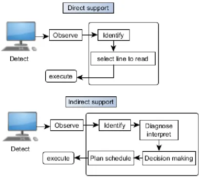
Based on how operators process the information, operator support systems are divided into direct support and indirect support systems [25]. In the direct support, the gathered information can be directly used to execute the actions without any significant interpretations. Therefore, it is needed that in the direct support systems, the information should be provided in the form of everyday language which is understandable by the operators and with less interpretation efforts. CBP, if it is considered as a kind of HMI, is an example of direct support system.
Figure 2.2-2. Information flow of direct and indirect supports
On the other hand, in the indirect support systems, operators need to interpret the perceived information before taking counter actions. Figure 2.2-2 summaries the
15 processing information for direct and indirect support systems [25]. It can be seen from the figure that in indirect support systems, after observing and identifying the information, operators should diagnose and interpret the information. The results can be used for decision making and plan schedule. Then, the actions can be conducted.
The direct support systems are more suitable for recovery action using the instruction and information provided in the EOP without interpreting the information.
In emergency situation, operators work in stressful condition. Therefore, they need clear and understandable instructions to execute the actions without any interpretation to mitigate the accident in limited time condition. While the indirect support systems are useful for interpreting the current condition based on the anomalies in the plant in order to recognize what has occurred and what is going on in the plant. The information from alarms, indicators and monitor lights should be interpreted and the results are used to make decisions.
2.3. Situation Awareness
Situation awareness (SA), in general can be defined as the ability of operators to establish and keep the adequate understanding of “what is going on” in the system for the successful of task performance. The SA can be measured by considering characteristic of the task and the aim of analysis. The concept of situation awareness initially was used in military to make the soldiers aware of the existence of the enemy.
Currently, the concept is adopted to aviation, nuclear power plant and emergency response [26]. There are several definitions about situation awareness (SA). However, mostly used definition is made by Endsley [27]: “the perception of the elements in the environment within a volume of time and space, the comprehension of their meaning, and the projection of their status in the near future”. Endsley also mentioned SA as a state of knowledge that results from a process (situation assessment).
Figure 2.3-1 summaries the definition of situation awareness. There are three levels of situation awareness: Level 1 (gathering information), Level 2 (Interpreting the gathered information) and Level 3 (anticipating future states). In case of nuclear plant, the Level 1 of SA is characterized by the needs of main control room operators to know the state of components, parameter levels such as pressure and temperature
16 level of a pressurizer in PWR plant, and alarm information regarding the anomaly in the plant. The ability of operators to understand, to analyze, to classify and to integrate the information perceived in Level 1 is the feature of Level 2 of SA. Finally, in Level 3 of SA, based on the achievements in Level 1 and 2 of SA, operators should be able to predict and anticipate the future events and impact of their actions.
Therefore, situation awareness is how operators know the current state of the plant [28]. The situation awareness can be used to anticipate future plant behavior, to create appropriate operation plan and to prevent potential failures [29].
Figure 2.3-1. Situation awareness and decision making [27]
In some cases, there are some factors or reasons that cause people may fail in achieving the situation awareness. It can be happened, especially in Level 1 and Level 2 of SA as mentioned by Endsley [27] and in [26]. In Level 1 of SA it can be caused by the unavailability of the data, the difficulty to perceive the data, failure to observe
17 the data and misperception of data. In addition, the lack of mental model, the use of incorrect mental model and memory failure are the factors that cause the fail in achieving SA in Level 2 of SA. Furthermore, there are some indications that people losing the correct situation awareness, such as: ambiguity, confusion, lack of required information, failure to maintain critical tasks and failure to meet expected target [26].
In nuclear power plant operation, situation awareness is very important and should be improved. There are some skills that can be improved to enhance the situation awareness in the area of planning, problem solving, attention, team coordination, knowledge and communication [26].
There are some factors that affect the situation awareness: individual factors and system factors [30]. Individual factors consist of attention and working memory.
Attention is related with the operator receiving information relevant with the task and whole description of the plant state. Working memory is used to store the information perceived in level 1 of SA and then to integrate with the new information for level 2 of SA and finally to determine how the future plant behavior is affected by the information in level 3 of SA. In order to manage attention and working memory, some aspects such as mental models, goal-driven processing, and automaticity should be considered [27]. Mental models are indicated by the ability of operators to achieve SA by processing and understanding a large amount of information. It can be established through training and experience. In addition, a specific goal (to develop SA) should be as a basis in the process of perceptions, interpretations and judgements to achieve the goal-driven processing. Moreover, automaticity is represented by the actions which need few attentional resources.
On the other hand, the system factors consist of interface design and system complexity. SA can be improved by providing good interface design which has information integrated from various sources or presents only information that operator must attend [31]. There are some external factors that influence the situation awareness: task, system, and individual [27]. The task environment includes task complexity, workload and pressure and stress. In an emergency condition, some tasks should be conducted to bring the plant to a safe operation state in limited time. In some cases, this condition will make them stress and then reduce the situation awareness. In addition, the necessary information provided by the system also affect
18 the situation awareness. Emergency operating procedures with insufficient information provided can cause operators to make a mistake in making decision and taking the actions to mitigate the accident. Finally, the individual also affects the situation awareness in terms of ability to achieve the situation awareness, ability to process the information, and objectives to interpret the environment.
Situation awareness can be simplified as the ability of operators to know what is going on around them. It is relevant with the concept of four cornerstone in resilience: learning, monitoring, anticipating and responding [32]. The features provided in the functional information will increase the ability of operators in perceiving and comprehending the information and also predicting the future event in situation awareness, which in turn will support the ability of monitoring and anticipating in resilience engineering. Monitoring or “knowing what to look for”
expresses that operators of a main control room should monitor the plant status and be able to find the initiating event related with the anomaly indicated by alarm and changes of parameter levels of components in the plant. In addition, the ability of operators to direct the potential changes and their impacts due to the counteractions (automatic or human actions) is a part of anticipating or “knowing what to expect”.
It is also related to the ability to identify the possible future behavior, conditions or state changes that affect the functionality of the system. The next section will discuss the resilience engineering.
In an emergency situation, operators may feel confuse, nervous, panic and stress during their activities to identify, control and mitigate the accidents. In some cases, it will reduce the situation awareness of the operators, which in turn it will increase the potential to human error and will endanger the plant. Therefore, in order to keep and increase the situation awareness, the situation awareness of operators should be regularly assessed or measured. There are some methods to measure the situation awareness, as mentioned in [33]:
- Freeze probe techniques
As the name, this technique freezes a random task and blanks all displays and screens and applies a set of SA queries regarding the current situation. The queries are developed by the Subject Matter Experts (SME). Then,
19 participant should response the queries based on their knowledge and understanding, and the results are compared to the state of the system at the freeze point and the SA scores are calculated. Despite the benefit, which is the “direct” SA assessment, this technique has some drawbacks in terms of the level of intrusion during the task and the validity because it more relies on the memories of the participants. An example of this technique is Situation Awareness Global Assessment Technique (SAGAT) which is described in [27]
- Real time probe techniques
This technique is the development of freeze technique in which the task proceeds in real time and is not frozen. Although, this technique still has problems as in the freeze probe technique, the advantage is, the level of intrusion can be reduced. Literature [34] mentions Situation Present Assessment Method (SPAM) as an example of real time probe technique.
- Self-rating techniques
These techniques are conducted as post trial and intended to derive the subjective rating of participants’ perceived SA through a rating scale. The techniques are easy, quick and low cost to implement and do not have intrusion. However, the drawbacks of the techniques are related with the collection of SA data post-trial and their sensitivity. The Situation Awareness Rating Technique (SART) is an example of self-rating techniques [33].
- Observer techniques
The SA is measured by SME and based on predefined observable SA related behaviors expressed by participants during task performance. These techniques can be used in the real worlds because they have no impact on the task being performed although they have some questions related to the validity. An example of the technique is the Situation Awareness Behavioral Rating Scale (SABARS) which is used to assess infantry SA in field training exercises [33].
20 - Performance measures
The SA is assessed based on the performance of the participants during the task and recorded to determine the indirect measure of SA. In military fields, the performance is indicated for example by the “kills”, “hits” or mission success or failure [33].
- Process indices
In these techniques, the way of operators maintains the SA during task performance is recorded. For example, using eye tracker to measure participant eye movements during task performance, which is used to gather information about which parts that got more attention by the participants [33].
Furthermore, in the field of nuclear power plants, as mentioned in [26], some skills of operators should be improved to enhance the situation awareness: planning, problem-solving, attention, team coordination, knowledge and communication.
2.4. Resilience Engineering
Safety, in general can be defined as a condition in which there are no undesired issues such as incidents or accidents. It also can be defined as the ability of system to ensure that the disturbances to workers, the public and the environment are acceptably low [35]. Regarding the concept of safety, Hollnagel [35] defined the safety into Safety-I and Safety-II.
Safety-I focuses on what goes wrong in the system and assumes different views of work and activities. “Things go right” if the system is functioned and people work as expected. On the other hand, if there are malfunctions or failures it is said that
“things go wrong”. Figure 2.4-1 summarizes the different views. The level of safety in safety-I is determined by how many things go wrong in the system.
21 Figure 2.4-1. Different views of work and activities in safety-I [35]
Moreover, safety-I concerns about finding the cause of the events, developing an appropriate response and action to mitigate and eliminate the events that harm the system. Another concern is the prevention of transition from normal to abnormal state by increasing compliance and eliminating variability [35].
Unlike Safety-I, the concern of Safety-II is “what goes right” which means that systems should be functioned under varying conditions and more focus on the understanding of why things go right. If the system goes wrong, the first thing to do is to understand how it always goes right and do not have to find the causes which only describe the failure [35]. Literature [36] summarizes the difference between the concept of safety-I and safety-II as can be seen in Table 2.4-1.
Table 2.4-1. Safety-I and Safety-II [36]
Safety-I Safety-II
Definition Determined by the number of things go wrong
Determined by the number of things go right
Management of safety Reactive, respond when something happens
Proactive, try to anticipate developments and events Accidents explanations Caused by failures and
malfunctions
Things basically happen in same way, regardless of the outcome
Human factor view Liability resource
The concept of Safety-II is relevant with the resilience engineering. After the Fukushima nuclear power plant accident in 2011, the concern of safety concept change from safety-I to safety-II. The purpose of resilience engineering is to prevent things from going wrong and to assure that things go right. A system is said to be resilience if it can adjust its functioning before, during, or following changes and disturbances [37].
22 Moreover, resilient engineering is not about reaching a level of safety but how well the organization performs and also does not characterize a state or condition but focuses on how process or performance are carried out [26]. Therefore, becoming resilience is different from becoming safe.
Figure 2.4-2 shows the principles of resilience engineering or the four cornerstones of resilience engineering [32]. “Knowing what to do” is related with the ability to focus on the actual which is how to respond to regular and irregular disturbances by applying a set of responses. “Knowing what to look for” is the ability to monitor a risk or a potential risk in the near future. It is related with the ability to address the critical. In addition, “knowing what to expect” is the ability to address the potential, which is how to anticipate potential changes, deviations, pressure and their consequences. Finally, the ability to address the factual is important in “knowing what has happened”, which is how to learn from experience both successes and failures.
Figure 2.4-2. Four cornerstone of resilience engineering [32]
Figure 2.4-3. Step to resilience (adopted from [38])
23 There are some steps for people or systems to achieve resilience [38], as can be seen in Figure 2.4-3. These steps related with the improving the four abilities differently but not independently. First, for the dysfunctional system, the system only has ability to respond the regular and irregular condition in effective and flexible manner. Then the abilities are improved to respond and to monitor. The ability to monitor related with the monitor short term developments and threats and revise the risk models. In this level, a system is in the reactive safety management system. If the system can improve its abilities with the ability to learn from the past events and understand what happened and why, it becomes in the level of proactive safety management system. Finally, the system is resilience if it develops all the abilities including to learn, to respond, to monitor and to anticipate (related with the long-term threats and potential).
This thesis focuses on the ability to monitor and to anticipate. As mentioned before that monitoring is the ability to monitor a possible threat in the near term which happens in the environment and the system itself that need a response. In order to properly monitor the system and the environment, a set of valid and reliable indicators is needed [39]. Moreover, the time and resources are required to be available and need to have a monitor strategy which involve skills and knowledge [40]. In case of nuclear power plant, it includes looking at the right instruments and indicators (alarm and trends) in the control room, looking through the procedure and monitor the procedure progress to ensure that it is properly completed. If the indicators are absent, operators should rely on their plant knowledge, situation awareness and problem solving skills [39].
On the other hand, anticipating is the ability to anticipate the potential changes, disturbances, changing operating conditions in the near future and their consequences.
It is related to the ability to address the potential and knowing what to expect and more influenced by learning from the past. It also includes the capability to see things from different views. Anticipating, compare with monitoring, it is not data-driven and rarely a time-critical function. Factors affecting the ability to anticipate are, for examples, knowledge and experience, quality of information and the operating procedures [41]
The operating procedures have correlation with the ability to anticipate provided that they have an explicit purpose of each procedure and notes and warning to indicate
24 that something happened in the system due to the deviation of parameter level of components. Monitoring and anticipating require operators to look forward in the procedures and in the operations as a whole as a means to get ready for the future events [39].
2.5. Functional Information
Nuclear power plants are equipped with automatic systems which will be actuated when an anomaly happened in the plant in order to trip the reactor to stop the fission reaction, and so on. However, the role of humans as nuclear operators is very important to maintain the safe operation and to mitigate the accident and also bring back plant to a safe condition. As mentioned in the previous section, the roles of operators include monitoring and controlling tasks. In order to complete the task properly, necessary information is needed for the operators. Such information are, for examples, the status of components or equipment, operating state of equipment, values of process parameters and condition of equipment and structures [42].
Presentation of information should simple and support the operators to perceive information easily, and also avoid misunderstanding and cognitive complexity.
The common information display systems provide the behavioral and structural information which is useful to understand the plant situation. However, because of the absence of information from the intentional aspect of plants, it is difficult to understand the goal and purpose of counter actions mentioned in operating procedures or suggested by an operator support system [43] Therefore, the concept of functional information [43] was introduced which express the system in a high level of abstraction and why a component exist in the system [7]. As mentioned by Gofuku in [7] that “functional information can be a language to bridge a human and a machine as it corresponds with the goal-oriented thinking and the understanding process of a human”. In addition, functional information should be displayed together with behavioral, structural and operational information. Functional information describes the reason and background of components that are important for operators to understand the plant situation and the suggested actions by the operating procedure.
The functional information is also useful for understanding the anomalous situation
25 in a system, and finding the plausible counter actions beyond that has been prepared in the operating procedures [7].
In order to get the functional information, systems are represented in functions and objectives that are interconnected using inference relations (functional modeling).
The inference relations indicate the cause and effect relations among function and between functions and objectives. The functional modeling can be explained by giving an example of car as discussed in [7] and shown in Figure 2.5-1 and Figure 2.5-2. There are two types of car based on the generating the driving force, by gasoline (Figure 2.5-1. a) and by electric power (Figure 2.5.1.b). The structure, components and principle to generate the driving force between the two types of cars are different.
However, the two types of the cars have the same purpose or function as means to travel or to carry baggage. Therefore, in terms of function or purpose, the two cars can be redrawn in the same hierarchical model as can be seen in Figure 2.5-2.
a. Gasoline engine car b. Electric car
Figure 2.5-1 Structure models of a gasoline and an electric car [7]
Figure 2.5-2. Functional model of a car [7]
26 Literature [7] mentioned that functional information has some benefits such as:
• System’s behavior can be associated with the role and purpose of each component. It is useful for displaying information how to overcome an anomaly situation.
• The influence and cause-effect relation, in the functional modeling can be used to predict the qualitative effect and influence of an operation or a system failure.
• The system’s behavior can be understood by the hierarchical structure in the functional modeling.
• The semantic gap in communication between operators and computer is reduced because of the capability of linguistic representation in functional modeling.
27
Chapter 3
3. Techniques to Derive the Additional Information Based on MFM Models
3.1. Overview of MFM
Multilevel flow modeling [4, 45, 46] was developed to model a complex plant system in terms of goals, functions, multiple levels of means-end and part-whole abstraction [46]. The means-end concept is used to model the system functions (means) to achieve goal/subgoals (end). In addition, in the part-whole concept, systems can be represented as a whole or subsystems in a hierarchical way [47]. MFM has three basic concepts: goals (objectives or purposes of the systems); functions (means to obtain the goals); and physical components (equipment to build the system) [48].
Gofuku [49] mentioned that by changing the abstraction level, it will make it easier to deal with a complicated system such as nuclear power plants for designing and managing the abnormal situation of the system. MFM has been implemented, for example, for operator support system in supervisory control [50, 51] and dynamic operation permission system [24, 52]. In addition, MFM can be used to express the information related to the plant condition in linguistic form. This functional information is very important for supporting the operators conducting their tasks to monitor and control the plant.
MFM is a method to represent complex industrial system in term of functions and objectives and the interconnection among them in high level of abstraction. Unlike other object-oriented modeling, MFM offers some benefits. In other object-oriented modeling (such as UML or hierarchical colored Petri-net), as mentioned in [53], the validity of diagnosis result is the main focus and do not reveal the diagnosis process to the operators. It means that operators do not understand what happened in a diagnostic system based on other-oriented modeling techniques. On the other hand, MFM provides comprehensive diagnosis based on perspective of human on the objective of the system. MFM breaks down the system into means-ends and whole- part dimension. In the means-ends dimension, MFM depicts the relationships among functions to achieve the system objective. On the other hand, the system is described
28 in different levels of aggregation in whole-part dimension. In addition, MFM provide realization relation which corresponds physical components with their functions, for example, function of transporting water can be realized by a pump. Furthermore, another important aspect of MFM is its ability to conduct consequence reasoning which is very useful for assessing the plant situation and system performance. The consequence reasoning is based on influence propagation, which indicates that the change of state of a function or objective will change the state of other neighboring functions or objectives (downstream connections). Regarding this study, the consequence reasoning and influence propagation are very useful to comprehensively gather the proposed additional information (components influenced and future plant behavior).
3.2. MFM Symbols
Figure 3.2-1 shows the MFM symbols used for constructing an MFM model. The symbols consist of functions primitives (such as source, transport and storage) and relations (influence, means-end and control). The function primitives correlate with the plant components. For example, a transport function is correlated with a pipe and a tank is represented by a storage function. An MFM model generally consists of mass flow structures, energy flow structures, control structures and objectives.
Each function primitive is connected by influence relations (influencers or participants). The influencer means that the relation influence the amount of material delivered by a transport function connected to a flow function (source, sink, storage or balance). If the transport function is passively provided or received material from the flow function, it is said that the relation is participant. Moreover, other relations are means-end relations which connect flow structures with objectives (produce, maintain, destroy and suppress) or connect function primitives with flow structures (produce-product and mediate). The flow sturctures or functions represent means to achieve objectives (end).
29 Figure 3.2-1. MFM symbols
3.3. MFM Reasoning
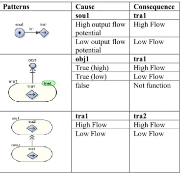
As mentioned in previous section that MFM is a tool to represent the complex industrial plants in block of symbols that correlated with functions and goals. In addition, it is also a tool to analyze and reason about the system performance based on relations between states of functions and objectives. Cause-effect relations are used to conduct reasoning in MFM. Owing to the fact that MFM decomposes a complex system in means-ends and whole part dimensions, the cause-effect in both dimensions has to be considered [54]. Therefore, there are two patterns related with the cause-effect relations involving “goal to function” and “function to function” in MFM models: influence relation and means-end relations [45].
Influence relations
The flow structures are constructed by the interconnected function primitives. The interconnections also created the cause-effect relations between states of function primitives. The relations are called influence relations. There are two types of influence relations: direct influences and indirect influences. As mentioned before that the cause-effect relations are based on the states of the function primitives, the state of the function primitives in the MFM model should be defined as provided in Table 3.3-1.
30 The definition of the states of MFM is based on [55]. However, in this thesis, some modifications have been proposed in order to cover some conditions in real plants. Such modification, for example, is to treat “no flow” in “transport” function primitive, which indicates that there is no mass/energy transferred from one component to another component. The underlined states indicate the modified parts of the definition. The “no volume” state is additionally defined to treat no liquid mass condition of a tank-type component.
Table 3.3-1. Definition of state of MFM
Symbols States
source normal, high output flow potential, low output flow potential, no output flow potential
sink normal, high input flow, low input flow, no input flow transport normal, high flow, low flow, no flow
storage normal, high volume, low volume, no volume barrier normal, leak
balance Normal (balance), unbalance (fill or leak) threat exist (high), exist (low), non-exist objective true (high), true (low), false
In direct influences, the influence is indicated by how transport functions influence other function primitives. The function primitives connected to a transport function in the mass or energy flow will be influenced by the state of the transport function in both its upstream and downstream directions [54]. On the other hand, if the transport function is influenced by other function primitives, it is called indirect influences [54]. The influencer and participants connections impact the influence in the indirect influence but not in the direct influence. Literature [55, 57, 46] describe the detail about the formulas for direct influence and indirect influence and some examples are provided in this thesis. The examples of rule for direct influence for both upstream and downstream connections, adopted from [56] are provided in Table 3.3-2. On the other hand, the rule for indirect influence is different between with influencer relations and participant relations, as can be seen in Table 3.3-3 and Table 3.3-4, respectively.
![Figure 2.1-1. Procedure hierarchy for various operation condition[8]](https://thumb-ap.123doks.com/thumbv2/123deta/5838050.1037835/14.892.182.768.801.1003/figure-procedure-hierarchy-various-operation-condition.webp)
![Figure 2.3-1. Situation awareness and decision making [27]](https://thumb-ap.123doks.com/thumbv2/123deta/5838050.1037835/25.892.150.775.426.916/figure-situation-awareness-decision-making.webp)
![Figure 2.5-1 Structure models of a gasoline and an electric car [7]](https://thumb-ap.123doks.com/thumbv2/123deta/5838050.1037835/34.892.181.753.583.762/figure-structure-models-gasoline-electric-car.webp)
![Table 3.3-3 Indirect influence with influencer relations [56]](https://thumb-ap.123doks.com/thumbv2/123deta/5838050.1037835/40.892.183.714.213.429/table-indirect-influence-influencer-relations.webp)