Damage Identification in CFRP Grid Structures by Strain Monitoring with FBG Sensor Network
__________________________________________________________________________________________________________
MASATARO AMANO, YOJI OKABE, NOBUO TAKEDA, HAJIME TAKEYA, AND TSUYOSHI OZAKI
ABSTRACT:
Advanced grid structures (AGS) made of carbon fiber reinforced plastic (CFRP) have often been applied to aerospace structures because of some advantages, such as the load transfer only in the direction of reinforcing carbon fibers in ribs and the fail-safe structure.
In this research, the authors constructed a health monitoring system for the AGS to identify damages in the structures.
First, the authors performed low-velocity impact tests to the ribs of CFRP unidirectional laminate. As a result, it was found that a partial crack appeared because of the micro-buckling of the carbon fibers. After that, an improved finite element modeling of AGS was proposed using 3D beam elements and liner constraint equations, which can represent the partial crack appropriately. The calculation results showed that the longitudinal strains of ribs only near the damaged locations changed drastically.
On the basis of the above results, multiplexed fiber Bragg grating (FBG) sensors were integrated into the AGS to measure the longitudinal strains of all ribs. Then, in order to identify damaged ribs robustly from the measured strain changes, a statistical damage recognition method was proposed based on the consecutive outlier analysis. Finally, the authors verified experimentally this health monitoring system. An AGS plate of about 0.5m
× 0.5m was manufactured and 39 FBG sensors were attached on the lower surfaces of the ribs. Two partial notches were formed artificially in two ribs, and the changes in longitudinal strains of the ribs between the intact and the damaged states were measured with the FBG sensors under the concentrated load applied on one nodal point. Then the damage recognition method was applied to the measured strain changes. As a result, the damaged regions could be well identified automatically. Hence, this system was found to be effective to the health monitoring of the AGS.
_____________
Y. OKABE: Dept. of Aeronautics and Astronautics, School of Engineering, The University of Tokyo, 7-3-1 Hongo, Bunkyo-ku, Tokyo 113-8656, Japan E-mail: [email protected]
M. AMANO and N. TAKEDA: Dept. of Advanced Energy,
Graduate School of Frontier Sciences, The University of Tokyo H. TAKEYA and T. OZAKI: Advanced Technology R & D Center,
Mitsubishi Electric Corporation
INTRODUCTION
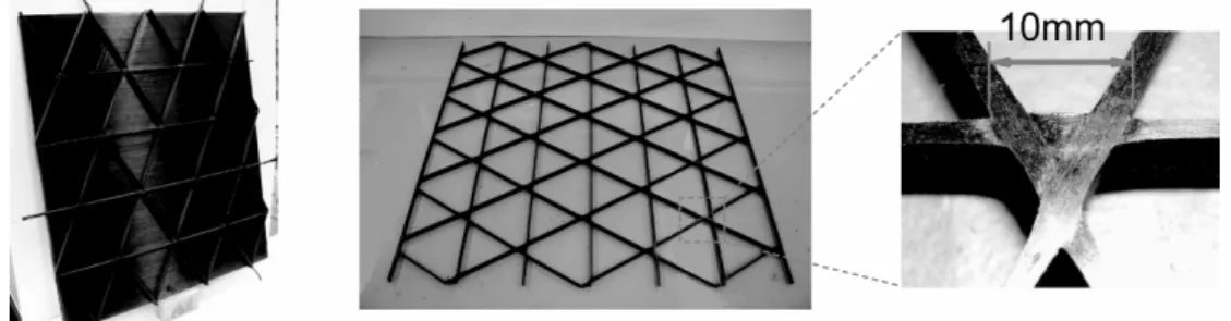
In recent years, a grid structure [1] made of carbon fiber reinforced plastic (CFRP) unidirectional composites, named as an advanced grid structure (AGS), has often been applied to aerospace structures (Figure 1). This structure has several advantages compared with other conventional structures [2]: (1) since ribs carry only axial forces, the weakness in the transverse direction of the CFRP unidirectional laminates is negligible. (2) AGS is a fail-safe structure because the fracture of a rib hardly affects other ribs. Although AGS has been restricted because of its difficult fabrication, recent fabrication technologies overcome the difficulty and AGS is now obtaining attention again [3].
Figure 1: Advanced grid structures made of CFRP unidirectional composites.
In order to improve the reliability of the AGS, the authors are constructing a structural health monitoring (SHM) system for the AGS with fiber Bragg grating (FBG) sensors for static strain measurement. Since all ribs of the AGS are composed of CFRP unidirectional laminates, optical fiber sensors can be easily embedded into the ribs during the manufacturing process. Furthermore, axial strain of all ribs can be measured with few optical fibers by multiplexing many FBGs into one optical fiber, because all ribs connect beyond every intersection [4].
As a preliminary research, the authors performed low-velocity impact test to the ribs to investigate the damage types caused by impact loadings. On the basis of the observation results of the impact damage, an improved finite element modeling of AGS was proposed and the change of the longitudinal strain in each rib was investigated through the calculation. Then, in order to identify damaged ribs robustly from the strain changes measured by FBG sensors, a statistical damage recognition method was proposed based on the consecutive outlier analysis. Finally, the authors verified experimentally the effectiveness of this health monitoring system.
DAMAGE CHARACTERISTICS
In this research, impact loadings, such as tool dropping or impact of debris, are considered as damage source. Hence, transverse low-velocity impact test was carried out.
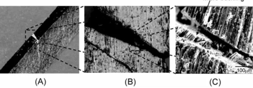
A drop weight impact tester (Dynatup 930-I, Instron Co.) was used for the test and the specimen was cut from fabricated AGS. Figure 2 is a group of photographs representing impact damage features taken with (A) a digital camera, (B) an optical microscope and (C) a scanning electron microscopy (SEM), respectively. As shown in Figure 2(A) and (B), rib cracking and fiber discontinuity were observed. Moreover, as shown in Figure 2(C), since the fracture surface is relatively flat, this damage feature was found to be the result of fiber
micro buckling. On the other hand, rib intersections were also investigated under the same impact loading. However, no damage feature was observed in the intersections. From these results, the partial crack in ribs is considered as the target of our SHM system.
Figure 2: Photographs taken with (A) a digital camera, (B) an optical microscope and (C) SEM. These represent the damage feature of a rib caused by low-velocity impact.
ANALYTICAL DISCUSSION
On the basis of the damage observation, an analytical model was constructed using finite element analysis (FEA) to confirm whether monitoring of the axial strains of ribs could be effective for damage detection.
Figure 3 illustrates the schematic of the model with 3D beam elements. At first, every beam element was divided into two elements in thickness direction, (d) and (i). The thicknesses of the two elements, td and ti, are determined from the length of a partial crack in a rib. Then, the following five constraint equations were introduced between the two elements with the function, Linear Constraint Equations, which ABAQUS offers [5].
2 0
2 3 3
1
1i − d −ti i −td d = u
u θ θ , u2i −u2d =0,
2 1 0
3
3 + =
−
− d i d i
i t t
u
u θ , θ1i −θ1d =0, θ2i −θ2d =0 (1) where u and θ represent displacement and rotation of nodes. In addition, subscripts represent the local coordinates as shown in Figure 3 and superscripts represent the corresponding regions. After assuming a partial crack in a certain location in a rib, we determine td from the length of crack and set all mechanical properties of the crack elements about 0.
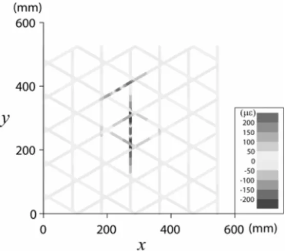
By using this model, the authors calculated the strains along fiber direction. Figure 4 illustrates the calculation modeling, where specimen was loaded of 1000N at one point and four edge lines were simply supported. The dimensions of the panel are about 53cm × 55cm × 1cm and the length and the width of each rib are about 93mm and 1.8mm. In the calculation, we assumed two damage points as shown in Figure 4 (td = 5mm).
At first, strains were calculated in two types of structural conditions: (1) undamaged, εintact, and (2) damaged at two ribs, εdamaged, where ε represents rib longitudinal strains of all elements as vector form. Then, the difference Δε = εdamaged − εintact was calculated. The
calculated Δε was visualized in Figure 5 as a contour map. Δε near damaged ribs largely deviated from 0. In contrast, Δε of other ribs almost equal 0. Hence two damage locations can be distinguished clearly. This result indicates that the AGS inherently has redundancy and the Δε can be used for damage detection.
Figure 3: Schematic of damage modeling with 3D beam elements.
Figure 4: Finite element model of AGS. Figure 5: Contour map of Δε. STATISTICAL DAMAGE RECOGNITION
The next step for constructing SHM system is to judge from measured data whether the condition of the structure has deviated from its normal operational condition. Hence a new statistical damage recognition system was proposed for this SHM system.
As mentioned above, Δεi changes drastically only near damaged ribs. Thus Δεis near damaged ribs can be considered as outliers in the whole data. Moreover, the others are so small that they can not be distinguished from measurement errors that generally follow normal distribution. Hence we assume that the others also follow normal distribution.
From these assumptions, a concept of damage recognition is proposed. When the changes in the longitudinal strains of some ribs have largely deviated from others, namely they can be considered as outliers, we can judge damage existence and identify approximate
damage locations. In this research, in order to recognize some data to be outliers, a statistical discordancy test is utilized [6, 7].
Discordant outliers in a data set are the data that are inconsistent with the rest of the data and therefore are considered to be generated by an alternate mechanism to the other data. They are compared to the rest under some objective criterion to be judged statistically likely or unlikely. One of the most common tests for a two-sided discordancy test of a single outlier in a normal sample is based on deviation statistics and given by
⎟⎟⎠
⎞
⎜⎜⎝
⎛ − −
= s
x s
T x x min x
max ,
max (2)
where x, x and s correspond to the measured data, the mean and standard deviation of the data, respectively. If T exceeds a threshold value corresponding to certain significant level, the corresponding data x is determined to be an outlier. In this research, we regard changes in longitudinal strains at all ribs Δεi as random variables X1, X2, …, Xn and a set of measured data x1, x2, …, xn is the sample of the variables. Since multiple outliers should be detected in this research, we also introduced ‘a consecutive test of up to k outliers’. At first, we estimate the number of contaminants k in the sample, which is determined by the number of outliers in the most serious structural damage conditions in AGS. Then, the equation (2) is modified as follows.
(j k)
s x s
x T
j j j
j
j min 1,2, ,
, max
max ⎟⎟ = K
⎠
⎞
⎜⎜
⎝
⎛ − −
= x x
(3)
where xj and sj correspond to the mean and standard deviation in subsamples S1, S2, …, Sk, where Sj is the set of data excluding x1, x2, …, xj-1. First, we calculate T1 in the complete sample, where T1 determines the most deviated sample as x1. Then, we calculate T2 in the sample of n-1 data without x1, and so on. Hence, x1, x2, …, xk (for prescribed k) are the samples that have possibility to be outliers in subsamples S1, S2, …, Sk. Once k data are removed, no outliers must exist in the rest of data. This consecutive procedure of reducing size in reverse order aims to protect against masking effects. Then, we determine λi(β), where the probability P[Ti > λi(β)] = β (for i = 1, 2, …, k) follows
[ λ ( )β ] =α
⎭⎬
⎫
⎩⎨
⎧∪k Ti > i
P 1 (4)
Subsequently, a level-α test operates as follows. If Tk > λk(β) then x1, x2, …, xk are discordant. Otherwise we conclude Tk to be normal and proceed by examining Tl for l = k-1, k-2, …, 1. When Tl > λl(β), we conclude that x1, x2, …, xl are adjudged discordant at level α, namely they are outliers. Thus, when existence of outliers is determined, we can conclude that damage exists. Moreover, the outliers tell us approximate regions of the damage.
EXPERIMENTAL VERIFICATION OF SHM SYSTEM
In order to verify the effectiveness of this SHM system, the strain measurement system of AGS with integrated FBG sensor network was actually established. Figure 6 shows the measurement system with multiplexed FBG sensors. The dimensions of the AGS panel are almost the same with them used for the above FEA. 34 plies of CFRP unidirectional prepregs were laminated in each rib (68 plies were laminated at cross points). In this experiment, 39 FBG sensors were multiplexed into seven optical fibers and attached on lower surface of ribs as shown in Figure 7.
Figure 6: Experimental setup. Figure 7: Serial numbers of ribs where FBG sensors were attached. 20th and 27th ribs were partically notched.
At first, the specimen was one point loaded on one nodal point with Instron1185(4400R) at the crosshead speed of 1.0mm/s. Under the loading condition, strains εintact were measured with an ASE light source, an optical switch (OSW8108, THORLABS Inc.) and a FBG sensor monitor (FB200, Yokogawa Electric Co.).
Subsequently, the specimen was unloaded at the same speed. Then, 20th and 27th ribs were partially notched as shown in Figure 8. Afterward, the specimen was loaded again and strains εdamaged were measured under the same boundary conditions. Finally, from the measurement results, the change of strains Δε = εdamaged − εintact was calculated.
Figure 9 represents measured Δε for all ribs. As shown in this figure, Δεis near 20th and 27th ribs, which were the damaged ribs, were much larger than other ribs and could be distinguished clearly as mentioned in the analytical discussion by FEA.
Figure 8: Photograph of partial notch.
Figure 9: Changes of strains Δεi versus rib serial number i.
Subsequently, the statistical outlier analysis was conducted for the measured Δε. In this research, we chose the significant level α = 0.05 and the estimation of the number of contaminants in the sample k = 5, which was determined by this experimental condition. A corresponding λi is shown in Table 1 [7]. As a result, 19th, 20th, 21th and 27th ribs are judged to be outliers. From the result, we can conclude as follows; this structure has a possibility of damage, and the damage must be near the outliers. Since the region estimated from the experimental results was the same as the real damaged region, we concluded that the SHM system for AGS was realized.
CONCLUSIONS
In this research, the authors proposed and realized a structural health monitoring system for AGS with embedded FBG sensor network.
In the beginning, in order to investigate impact damage that we should focus on, a low velocity impact test was conducted. According to the experimental result, we found that rib partial cracking caused by fiber micro buckling was the typical damage in AGS. Then, we calculated the change in strains induced by damage in AGS with an improved finite
i λi(β) 1 3.31 2 2.88 3 2.69 4 2.55 5 2.47
Table 1: Critical values for 5%
consequtive test for up to k = 5 outliers in a normal sample n = 40.
element modeling of AGS. The result confirmed that the change of static strains in fiber direction at all ribs was sensitive to rib cracking in AGS. After that, a statistical damage recognition method based on the concept of consecutive outlier analysis was also proposed and introduced in the SHM system to determine existence and regions of damage automatically.
Finally, we experimentally discussed whether our proposed SHM system could detect damage automatically. We actually constructed a strain measurement system of AGS with multiplexed FBG sensors and measured the change in strains of all ribs. In this experiment, we introduced rib partial notches in two ribs of AGS as impact damage. Then, we conducted the consecutive outlier analysis for the measured signals to determine whether the specimen was damaged and where the damage existed in the specimen. The result of the experiment proved that the system could clarify the existence and approximate region of damage in AGS.
ACKNOWLEDGEMENTS
This study was conducted as a part of the “Civil Aviation Fundamental Technology Program - Advanced Materials & Process Development for Next-Generation Structures”
project under contract with RIMCOF (R&D Institute of Metals and Composites for Future Industries), founded by the METI (Ministry of Economy, Trade and Industry), Japan.
REFERENCES
1. R.R. Meyer, O.P. Harwood, and J.I. Orlando, “Isogrid design handbook,” NASA-CR-124075, NASA Center for Aerospace Information (CASI). (1973)
2. H.-J. Chen and S.W. Tsai, “Analysis and optimum design of composite grid structures,” Journal of Composite Materials, 30, 503-534. (1996)
3. S.M. Huybrechts, T.E. Meink, P.M. Wegner, and J.M. Ganley, “Manufacturing theory for advanced grid stiffened structures,” Composites: Part A, 33, 155-161. (2002)
4. H. Takeya, T. Ozaki, and N. Takeda, “Structural health monitoring of advanced grid structure using multipoint FBG sensors,” in Proceedings of SPIE, Vol. 5762, SPIE, pp. 204-211. (2005)
5. ABAQUS Analysis User’s Manual &Theory Manual, ABAQUS Version 6.5 Documentation, Hibbitt, Karlsson &Sorensen, Inc. (2004)
6. K. Worden, G. Manson, and N.R.J. Fieller, “Damage detection using outlier analysis,” Journal of Sound and Vibration, 229, 647-667. (2000)
7. V. Barnett and T. Lewis, Outliers in Statistical Data, 3rd Edition, John Willey & Sons. (1994)