Increasing pose comprehension through augmented reality reenactment
21
0
0
全文
(2) 2. Fabian Lorenzo Dayrit et al.. One alternative that relaxes this limitation is to record the motion in a video, which allows the viewer to watch it at anytime and is widely accepted, especially for training videos. Unfortunately, using recorded video in turn poses a problem. The three-dimensional aspect of human motion may be lost since a standard video is a sequence of two-dimensional images and can only be watched from the viewpoint where it was captured. Viewers can, in most situations, infer the three-dimensional motion from the video. However, in the presence of any ambiguity, viewers may be unable to comprehend the exact motion, which can be problematic for those trying to imitate it. Augmented reality (AR) may offer us a solution to this problem. AR presents a virtual object, e.g. some textual information or a rendering of a real person, in a real world environment [4]. An example system that applies AR technology to human motion is YouMove [3] The system records the instructor’s motion using an RGB-D camera and displays it in stick figure form on a mirror in front of a learner who then tries to imitate the motion. One drawback of this system is that it does not render the appearance of the instructor, which seems essential for a more immersive experience of learning or watching performances. In this work, we propose the concept of a reenactment [9]. A reenactment is a rendering of a human actor, e.g., an instructor or a performer, and is presented to viewers through their smartphones, tablet PCs, and head-mounted displays. The reenactment can be viewed from any viewpoint, which is determined interactively and intuitively using AR technologies. Some types of reenactments are highly dependent on environment and must be presented at the place where they were captured, such as a parkour performance. Otherwise, they are independent of the environment and can be presented anywhere the viewer likes. One way to generate reenactments is novel view synthesis (NVS), which is a technique of rendering novel views of an object or scene. NVS specifically of humans is a well-studied topic [1] [6] [25] [26] [32] and these methods produce lifelike views, but they are mostly unsuitable for casual users, because their capturing processes are complicated. For example, all of these studies make use of multicamera systems, which must be set up at the target environment and calibrated before capturing. Additionally, it is next to impossible to capture motions with a handheld camera. This paper thus proposes a user-friendly system for capturing, synthesizing, and viewing reenactments. For easier capturing, it only uses a single RGB-D sensor data. We here focus on location-specific reenactments, but the techniques to generate these can easily be applied to location-agnostic ones. The main contributions of this work are: – We introduce the concept of reenactments, originally proposed in our previous paper [9]. Reenactments potentially have a wide range of applications, including training motions, watching performances, recording sports, etc. Our proposed system implements reenactments with AR technology, which lets users intuitively choose the viewpoint, and displays the reenactments in a natural way in the same location that the actor was captured. This kind of presentation through AR is novel, when compared to the existing methods of NVS. We also improve on the method described in the previous paper in order to generate reenactments of higher quality..
(3) Increasing Pose Comprehension through Augmented Reality Reenactment. 3. – We propose a new method for NVS from a single RGB-D sensor’s data, using a combination of Malleson et al.’s method [18] with view-dependent texture mapping (VDTM) [10]. In Malleson’s method, the human body is modeled as a piecewise combination of rigid body parts. We texture each body part individually using VDTM, taking into account the pose of the person in each captured RGB image as well as the camera positions. The novelty of this method is that it treats each captured RGB image as a view of each body part, allowing us to acquire multiple views of each body part with a captured sequence from a single RGB-D sensor, which VDTM can then use as textures. – We quantitatively evaluate the performance of our AR reenactment system in terms of its effectiveness in learning specific poses. We show that by viewing the AR reenactments, users are more easily able to comprehend ambiguous poses. We also subjectively survey the visual quality of the synthesized reenactment, as well as its applicability, and compare it to our previous work [9]. We found that while the visual quality is not at the level of standard video, it is much improved, and is enough to be easily comprehensible. The rest of the paper is organized as follows. We present related work in Section 2. We give the methodology of the system in Section 3. We describe experiments in Section 4, and summarize this paper in Section 5.. 2 Related work Our system helps users learn motion with AR by utilizing a form of NVS. In this section, we discuss some prior research in these fields.. 2.1 Learning motion with AR One common usage of AR is displaying virtual markers on real-world objects. For example, Hondori et al. [14] developed a system for users who have suffered a stroke that generates AR targets to reach for, grasp, or point to. These are repetitive motions that are often used in daily life, and are key to the process of rehabilitation. A similar system has been developed by Velloso, Bulling, and Gellersen [23] for physical exercises. It automatically provides feedback to the user on the parts of the motion that need improvement. Virtual arrows and labels can also be overlaid on specific locations, directing users to correctly perform complicated procedures such as assembly [12]. Alternately, the assembly components can also be completely simulated within the AR environment [24]. AR can also aid users who wish to learn, for example, the drums [28]. The system projects the target timing directly onto the drum pads, and provides instant feedback to the user, improving the user’s experience. The AR used in these applications excel at specifying targets for motion, but when there is no target or the motion is more complex than just hitting a target, a more explicit way to display motion is required. One system that does this is YouMove [3], which overlays an actor’s motions onto the viewer’s reflection in a mirror, making it easy for viewers to copy difficult motions. The viewers also had the ability to rotate the motion of the actor to better see where they may have made mistakes. However, the actor’s motions are overlaid as stick figures and not.
(4) 4. Fabian Lorenzo Dayrit et al.. as the appearance of the actor himself, which may introduce some confusion. On the other hand, we attempt here to render the appearance of the actor performing the motion using a form of NVS.. 2.2 Novel view synthesis One way to synthesize novel views of an object is by reconstructing and texturing a 3D model of that object, for example by generating a visual hull [19] from several images and converting it into the 3D model [17], as Pag´es et al. [20] do. This is model-based rendering, and once the 3D model has been reconstructed, it can easily be rendered and viewed from any viewpoint. However, it is usually not so easy to make this kind of rendering realistic, at least in the case of human motion. Humans move fluidly, folds appear in clothing, skin deforms in a certain way, and it is difficult to simulate this with simple polygons. With image-based rendering [22] (IBR), on the other hand, a large number of images are used to provide the appearance of the object. One major method of IBR is view-dependent texture mapping (VDTM) [10] which takes a simplified version of an object’s geometry and chooses images as textures based on viewpoint similarity. However, it assumes that the object is static, so it cannot be used for humans in motion. Another class of IBR renders an articulated object, such as an actor [27] or an article of clothing [11] [13] [31], by first searching for images with poses similar to the target pose, then slightly warping them to fit. Other methods of NVS specifically of humans in motion capture a moving actor using several cameras simultaneously in order to synthesize novel views. For example, Zitnick et al. [32], split up a scene into foreground and background, then interpolate between two captured cameras’ views. Waschb¨ usch et al. [25] use depth sensors to capture and merge point clouds. De Aguiar et al. [1] first create a detailed mesh model of the actor and then deform it using correspondences from multiple views. Multiple RGB-D sensors may also be used in real-time, e.g. for the purpose of teleconferencing [2] [5] [8]. The requirement of multiple views, however, may be difficult to fulfill for the casual user, due to the requirement of multi-camera systems which are difficult to set up and almost impossible to use as a mobile application. These may be combined with the pose-based criteria mentioned above in order to reduce the number of cameras needed for capturing. Carranza et al. [6] use sillhouette in order to reconstruct a model, which they then apply texture to. However, this method still requires several cameras in order to get the sillhouette from multiple angles, as well as to extract the texture. With depth sensors, the actor’s pose can be more easily estimated using, for example, skeleton tracking [21]. For example, Ye et al. [29] use three handheld Kinect sensors in order to capture an outdoor scene with multiple actors. The point clouds from each Kinect are integrated in order to reconstruct and texture a surface model of each actor, and the estimated human pose is used to help with this. Another example is Malleson et al. [18], who use a single Kinect sensor for capturing human motions and depth images. They take a more model-based approach, shaping each individual body part with voxels using the depth images and estimated human pose. Our previous system [9] uses a model-based approach as well, using a cylinder as each body part instead of its detailed shape model. In this article, we newly.
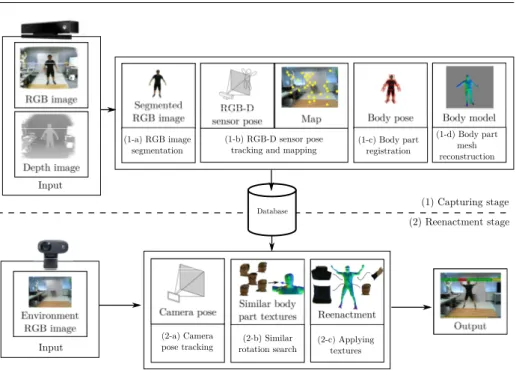
(5) Increasing Pose Comprehension through Augmented Reality Reenactment. (1-a) RGB image segmentation. (1-b) RGB-D sensor pose tracking and mapping. 5. (1-c) Body part registration. (1-d) Body part mesh reconstruction. Input (1) Capturing stage Database. (2) Reenactment stage. Input. (2-a) Camera pose tracking. (2-b) Similar rotation search. (2-c) Applying textures. Fig. 1: Overview of our proposed system.. adopt Malleson et al.’s method [18] to obtain a body model in order to increase the quality of the output. Since the appearance of the actor can change in the course of recording due to, e.g., lighting, we apply view-dependent texture mapping in order to texture the body model.. 3 AR reenactment system In this section, we describe the proposed AR reenactment system, which renders an actor’s performance from a novel, user-chosen viewpoint using RGB-D images captured from a single sensor. Figure 1 illustrates an overview of the system, which consists of two stages: Capturing stage and reenactment stage. The capturing stage (1) generates the 3D body model of actors from RGB-D images while estimating the body pose and relative camera pose for texturing purposes. First, we acquire RGB-D frames and extract the appearance of an actor by segmenting the actor in the RGB images (1-a) in each frame. The system also estimates the camera pose and generates the map of the environment using a simultaneous localization and mapping (SLAM) system, PTAMM1 [7] (1-b). It creates a map of feature points purely from RGB images and tracks the camera’s location relative to the map.. Here, the map is constructed as a collection of 3D points with visual information so that the system can estimate the camera pose in the reenactment stage. Body part registration (1-c) allows us to estimate the actor’s pose and build the actor’s body 1 PTAMM is a version of Parallel Tracking and Mapping [16], which is a visual SLAM system..
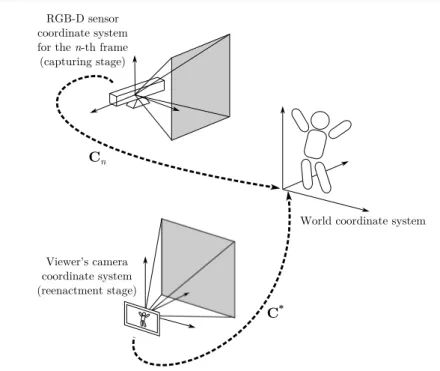
(6) 6. Fabian Lorenzo Dayrit et al.. model, which is a piecewise model made up of rigid 3D mesh models of body parts. In each frame, each body part’s pose is estimated, which enables us to reproduce the motion of the actor in the next stage. In body part voxel reconstruction (1-d), we combine these estimated poses with the depth image data in order to build up each body part’s shape. For the capturing stage and the reenactment stage, we assume that the RGB-D sensor and the viewer’s camera are calibrated using, e.g., [30]. The reenactment stage (2) renders the virtualized actor on a mobile display in an AR manner. For this, we use the captured appearance and motion in order to overlay images of the environment captured in real-time with a reenactment, i.e., a novel view of the actor. To render the view of the actor at the place the actor was captured, the proposed system uses the map stored in the database. It tracks the camera pose relative to the map (2-a), rendering the actor’s reconstructed body model as if it was being viewed from the viewer’s current location. Next, for each body part in our virtual view, we select the RGB images based on the similarity of actor poses (2-b), similar to the VDTM method. Finally, we apply the selected RGB images as textures to each body part (2-c). In the following section, we describe the different coordinate systems our system uses and how to transform between them, and how we calibrated the depth sensor to our camera pose tracker. Next, we describe the capturing stage and the reenactment stage. 3.1 Definition of coordinate systems and sensor calibration Figure 2 shows the coordinate systems in use. In the system, the world coordinate system is defined as a unique base of the coordinate system for both the capturing and reenactment stage, and is set as the camera pose in the first frame in the capturing stage. The camera pose is treated as a transform from a sensor coordinate system (i.e. RGB-D sensor or viewer’s camera) to the world coordinate system. Here, it should be noted that in practice, 3D points regained from the depth sensor on the RGB-D sensor and those in the SLAM system’s map are usually in different coordinate systems. Additionally, the depth sensor is distinct from the RGB camera, and thus there may be some slight translation or rotation between them. In order to correctly render our reenactment with the model, we must calibrate the transformation parameters, i.e. rotation R, translation t and scale s, among the coordinate systems. Fortunately, PTAMM [7] tracks a number of map points, which are feature points with estimated 3D coordinates in the world coordinate system. We can project each map point into the depth image to get the corresponding pairs of 3D points, which then gives us the transformation parameters. Given M map points, with pm as the position of the m-th map point relative to the RGB camera and qm as the corresponding point based on the depth image, we obtain the transformation from the skeleton tracker coordinate system to the RGB camera coordinate system as follows: M X ¯ ¯t, s¯) = arg min (R, kpm − (sRqm + t)k2 . (1) (R,t,s) m=1. This least squares problem can be solved by using singular value decomposition. From this point on, all points based on the depth sensor are assumed to have been.
(7) Increasing Pose Comprehension through Augmented Reality Reenactment. 7. RGB-D sensor coordinate system for the n-th frame (capturing stage). Cn. World coordinate system. Viewer's camera coordinate system (reenactment stage). C*. Fig. 2: Relationship among RGB-D sensor coordinates, viewer’s camera coordinates, and world coordinates.. transformed into the unique world coordinate system defined in the RGB camera coordinate system, i.e. the camera pose estimated from SLAM.. 3.2 Capturing stage In this section, we detail the processes (1-a) to (1-d), which estimate the camera’s and actor’s pose in each frame and reconstruct the actor’s body model. As the input for the processes, a user captures a sequence of RGB-D frames of an actor performing a motion sequence, consisting of RGB images {In |n = 1, ..., N } and depth images {Dn |n = 1, ..., N }. (1-a) RGB image segmentation We segment the actor from the background of the RGB images in order to achieve correct body part registration and correct texturing in the reenactment stage. Here, we employ the “BodyIndexFrame” functionality from the Kinect SDK, which tells us which depth pixels belong to our actor and which belong to the background. (1-b) RGB-D sensor pose tracking and mapping To obtain camera pose Cn for the n-th frame, we use PTAMM [7]. Cn can also be interpreted as the transformation from the current camera coordinate system to the world coordinate system. PTAMM also provides a map of the environment that is constructed of 3D points gained during visual SLAM, as well as their descriptors. This map is in the world coordinate system, which in our system is equivalent to the camera pose in the first frame, i.e. C1 is the 4 × 4 identity matrix..
(8) 8. Fabian Lorenzo Dayrit et al.. (1-c) Body part registration In order to build an accurate model of the actor’s body, we use Malleson et al.’s method, described in [18]. They define a model of the actor’s body that consists of body parts. In each frame n, each body part b has transform Tb,n , which defines its pose, i.e., its rotation and translation, for that frame. Each body part also has a voxel volume Vb , which defines its shape. Pose and shape are closely related, because the accuracy of the reconstructed shape depends on the accuracy of the estimated transforms: in order to correctly shape each body part, each volume must be correctly aligned in each depth image, and this process is called body part registration. For body part registration, Malleson et al. use a combination of point-to-point and point-to-plane ICP, with an additional constraint given by Kinect skeletal pose estimation, in order to register each body part in each frame. ICP works better with incremental transforms, and so given the previous frame’s transform Tb,n−1 , the current frame’s transform Tb,n is defined using a transform delta ∆T: Tb,n = ∆TTb,n−1 .. (2). ∆T is calculated over a number of iterations, until convergence, by minimizing the cost function: p s o (∆T), (∆T) + ws Eb,n Eb,n (∆T) = Eb,n (∆T) + wo Eb,n. (3). p o where Eb,n (∆T) is the point-to-plane term, Eb,n (∆T) is the point-to-point term, s and Eb,n (∆T) is the skeletal pose constraint term. Relative weighting coefficients wo and ws are applied to the terms. For our system, wo is set to 1 and ws is set to half of the number of voxels in Vb . For the point-to-plane term and point-to-point terms, we register the body part by attempting to fit the 3D points belonging to the body part on frame n − 1 to the 3D points on frame n, taking into account the difference in camera pose. The 3D points that belong to the body part are obtained by calculating the 3D coordinate of each depth pixel in depth image Dn−1 and taking those 3D points that are within the volume corresponding to the body part. Each volume has predefined dimensions according to the body part and takes the body part transform Tb,n−1 . For the first frame, we set each body part transform to the one estimated by the Kinect skeleton tracker. p Point-to-plane ICP term: The point-to-plane ICP term Eb,n (∆T) returns the sum of squared distances between each 3D point belonging to body part b on frame n − 1, which is regained from depth image Dn−1 , and the tangent plane on the corresponding point on the surface of frame n, which is a set of 3D points regained from depth image Dn . The point correspondences for point-to-plane ICP are defined as the point pairs having the same depth pixel coordinates across Dn and Dn−1 , taking into account the difference in camera pose between Cn−1 and Cn and the body part transform delta ∆T. o Point-to-point ICP term: The point-to-point ICP term Eb,n (∆T) similarly returns the sum of squared distances between each 3D point belonging to body part b on frame n − 1, which is regained from depth image Dn−1 , and the corresponding point on the surface of frame n, which is a set of 3D points regained from depth image Dn , with the difference being that the point correspondences are calculated using optical flow between color images In−1 and In ..
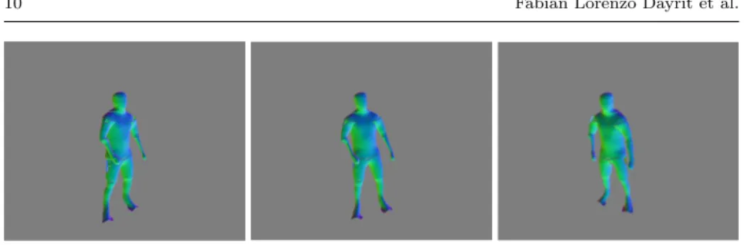
(9) Increasing Pose Comprehension through Augmented Reality Reenactment. 9. s Skeleton constraint term: The skeleton constraint term Eb,n (∆T) returns a measure of distance between the calculated body part transform Tb,n and the estimated body part transform T∗b,n acquired from the Kinect skeleton tracker.. In order to be able to solve the cost function linearly the small rotation angle assumption is used to define the transform ∆T as: 1 α −γ tx −α 1 β ty ∆T = [∆R|∆t] = (4) γ −β 1 tz . 0 0 0 1 The derivative of Eb,n (∆T) can then be computed for each component (α, β, γ, tx , ty , tz ), obtaining a 6 × 6 symmetric linear system, which is solved as in [15]. ∆T is composed onto Tb,n after each iteration. (1-d) Body part mesh reconstruction After estimating transform Tb,n for body part b in frame n, the corresponding depth image Dn is then used to reconstruct its 3D shape as a mesh model. For this process, we basically follow the method [18], with a slight modification. Here, the 3D shape of each body part is reconstructed as a surface model using the voxelspace signed distance function (SDF) [15] and the marching cubes algorithm [17]. Voxel volume Vb has predefined width Wb , height Hb , and depth Db and contains Wb ×Hb ×Db voxels. For each voxel, scores can be calculated indicating the average observed signed distance from the surface. Due to such uncertainties as fluctuating depth measurements, each depth image’s contribution should be limited. Thus, the SDF is truncated to the range [−µ, µ]. In addition to this, signed distances beneath the opposite side of the surface will usually be incorrect, as the opposite side is unobserved; therefore, to make the truncated SDF calculation more robust, each frame’s contribution that are less than −µ is ignored in order to avoid interfering with any possible surfaces on the other side. More concretely, the score is defined as follows: N X FDn (v) F (v) = , (5) N ∗ (v) n=1. µ FDn (v) = η(v) 0. : : :. µ ≤ η(v) − µ ≤ η(v) < µ , η(v) < −µ. (6). where η(v) is the signed distance from the surface to voxel v taking into account the transform Tb,n , µ is a predefined constant to truncate the SDF, and N ∗ (v) is the number of frames excluding those with η(v) < −µ. In the original method [18], depth pixels are assigned to body part volumes in order to avoid updating the wrong body part; however, we do not do this in our method. The volumes that we used had many overlapping regions at the joints, and assigning depth pixels to one body part or the other interfered with the voxel building. Skipping this depth pixel assignment usually results in slightly larger body part models; however, since we use view-dependent texturing, the quality of the output does not degrade. Finding the zero-crossings will thus give an estimate of surface locations. We apply the marching cubes algorithm [17] in order to convert these voxels into a mesh for each body part, as in Fig. 3..
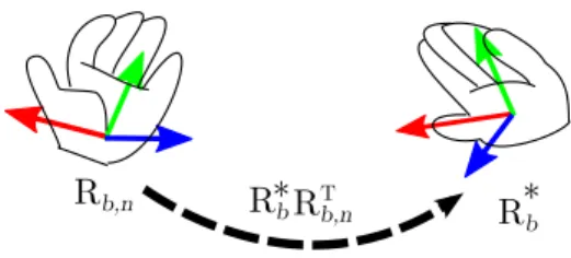
(10) 10. Fabian Lorenzo Dayrit et al.. Fig. 3: The generated body part meshes from different angles.. The system stores segmented RGB images {In |n = 1, ..., N }, camera poses {Cn |n = 1, ..., N }, body part transforms {Tb,n |b = 1, ..., B, n = 1, ..., N }, body part meshes {Mb |b = 1, ..., B}, and the map in the database.. 3.3 Reenactment stage In the reenactment stage, the viewer captures environment images in real-time using a mobile device and the system overlays these images of the real world with the reenactment, in the manner of AR. The following details the process for reenacting the pose (i.e., the pose of each body part b, Tb,n ) in the n-th frame overlaid on the real-time image I ∗ . (2-a) Camera pose tracking In order to render the reenactment in the place it was captured, we first estimate the viewer camera pose C∗ for real-time image I ∗ captured by the viewer, again using the visual SLAM technique [7], allowing us to estimate the camera pose in the world coordinate system which was defined in the capturing stage. We use the tracked camera pose C∗ in order to transform each body part to the viewer camera coordinates: T∗b = C∗ C−1 n Tb,n ,. (7). where b is the body part id and n is the frame. (2-b) Similar rotation search We then apply the appearance of the actor to the transformed body parts by using view-dependent texture mapping. Most existing techniques for NVS use multiple RGB/RGB-D cameras and sensors in order to reduce invisible regions due to occlusion [32] [6] [1] [25]. Since our system captures from a single RGB-D sensor, it instead uses appropriate RGB images over the course of the entire recording. We find appropriate textures for each body part using the similarity of the rotation components of their transforms as a metric. As in Fig. 4, we want to find frame n with the rotation that is closest to the rotation computed by equation (7): n ¯ b = arg min Φ(R∗b RT b,n ),. (8). n. where Φ(R) converts rotation matrix R into its axis-angle form and returns the angle, i.e., the magnitude of the rotation..
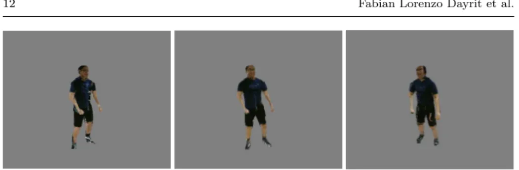
(11) Increasing Pose Comprehension through Augmented Reality Reenactment. Rb,n. T R*b Rb,n. 11. R*b. Fig. 4: The difference between captured body part rotation Rb,n and virtual rotation R∗b is expressed as another rotation R∗b RT b,n .. Fig. 5: Left: checking for occlusions by projecting different body part volumes onto a texture. Right: unoccluded regions for the chest body part.. (2-c) Applying textures We map all x∗ , the 3D positions of all visible pixels on the surface of the body parts, onto the corresponding transformed mesh as xn¯ b , which are then projected onto the 2D image in order to get the color at the corresponding pixel of RGB image In¯ b . xn¯ b = Tb,¯nb T∗−1 x∗ , (9) b x2D = ρ(xn¯ b ),. (10). where ρ(x) transforms a point into pixel coordinates by multiplying by the camera matrix and dividing by the z-coordinate. Since the actor is reenacted from a viewpoint different from those at which the textures were originally captured, it should be noted that xn¯ b can be occluded by other body parts as shown in Fig. 5. Background pixels can be detected by referring to the results of actor/background segmentation. In this case, we consider it to be an extraneous part caused by the simplified geometry model, and we show instead the corresponding pixel on the real-time image. To handle occlusion, we take the following strategy. First, the system detects the occlusion in In¯ b for body part b by projecting each body part in the appropriate pose for the n ¯ b -th frame, i.e. Tb,¯nb onto the In¯ b , testing for depth map rendered for all body parts(see Fig. 5). If the body part is not occluded, the projected body part and the depth map coincide. Otherwise the body part lies farther than the depth map and the system finds the next-best frame instead of In¯ b and repeats the process until it finds one in which the corresponding pixel is not occluded. The output is shown in Fig. 6. Finally, we overlay the environment image with the synthesized reenactment, as shown in Fig. 7..
(12) 12. Fabian Lorenzo Dayrit et al.. Fig. 6: Textured meshes for the surface model shown in Fig 3.. Fig. 7: Environment image overlayed with reenactment. 4 Experiment We implemented the proposed reenactment viewing system on a mobile device and evaluated its effect on users’ comprehension of actor’s poses. In this experiment, the effectiveness of the system is evaluated by checking the pose errors defined between the true pose and the pose recognized by subjects from the system’s output. We then confirm the quality and applicability of the proposed reenactment system compared to the previously developed system. 4.1 Implementation We captured motion sequences of performances using a Microsoft Kinect 2. We implemented our AR reenactment system on a Microsoft Surface Pro 2 with 4GB RAM and 1.60GHz processor. For skeleton tracking as well as actor-background segmentation, we relied on the implementation in the Kinect SDK [21]. Our body model contains 15 body parts, seen in Fig. 8. With this configuration, we achieved an interactive FPS ranging from 8 to 12 frames per second during reenactment. 4.2 Evaluation In order to evaluate the system, we experimentally tested users’ comprehension of actor’s poses with the reenactment compared with their comprehension with.
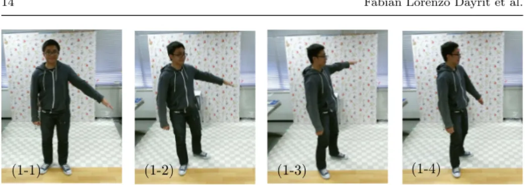
(13) Increasing Pose Comprehension through Augmented Reality Reenactment. 13. Fig. 8: 15 body parts used for body modeling.. conventional 2D images and video using 21 subjects. The experiment consists of two parts. Pose angle estimation. In the first part of experiments, users were tasked with estimating the angle of the actor’s arm. The actor was asked to form four different poses with specific angles between his arm and torso, and we captured these poses with both our proposed system and a conventional camera, as shown in Fig. 9. Each pose was captured from a different viewing angle, as illustrated in Fig. 10 and detailed in Table 1, in order to test the effect of viewing direction on angle comprehension. In order to aid our system in collecting textures, we also captured the actor from different points of view, asking him to hold the pose as still as he could. For each pose, we showed half of our users the conventional image, and the other half were made to view the pose as an AR reenactment using our proposed system. Users alternately viewed either the conventional image or the AR reenactment per pose. Specifically, users were divided into Group A and Group B. Users in Group A were shown Pose (1-1) and (1-3) in conventional images and Pose (1-2) and (1-4) using the proposed system, while those in Group B were shown the opposite. Users were asked to form the angle using a compass while viewing the pose. We then calculated the mean absolute error (MAE) for all users for the viewers of the conventional image and of the proposed system. Table 1 also shows the results of the experiment. The proposed system’s errors were generally lower than the conventional result. We can see that as the viewing angle of the conventional image increases, the arm angle estimation error also.
(14) 14. Fabian Lorenzo Dayrit et al.. (1-1). (1-2). (1-4). (1-3). Fig. 9: Conventional images depicting the poses which were shown to the users for pose angle estimation. In each pose, the actor forms a different angle with his arm. Each image is also taken from a different viewing angle.. Actor Arm direction. Viewing angle. Actor's front. Camera Fig. 10: Viewing angle shown from the top. A value of 0◦ means that the actor is facing the camera. Arm direction is always perpendicular to the actor’s front. Table 1: Pose angle estimation results. For the users’ answers, the mean absolute errors (MAE) for both the conventional images (conv.) and the proposed system (prop.) were calculated.. Pose Pose Pose Pose. (1-1) (1-2) (1-3) (1-4). Arm angle. Viewing angle. Conv. MAE. Prop. MAE. 47◦ 68◦ 95◦ 32◦. 0◦ 26◦ 46◦ 57◦. 7.25◦ 6.70◦ 10.48◦ 10.59◦. 7.62◦ 9.01◦ 3.11◦ 4.90◦.
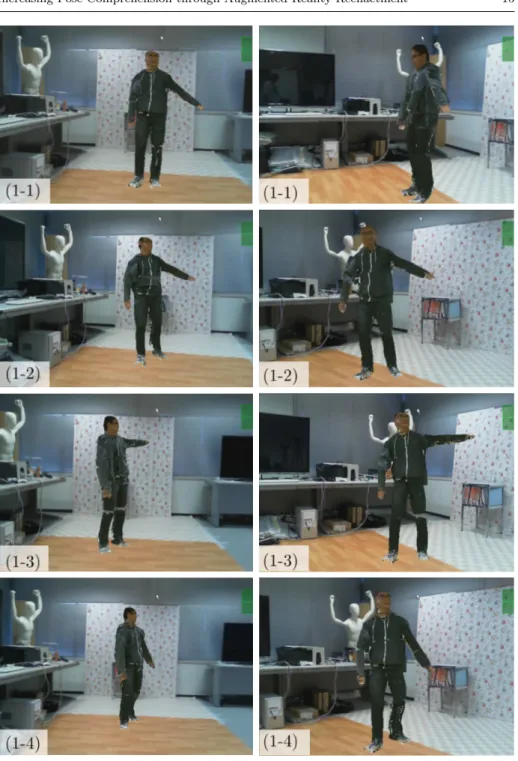
(15) Increasing Pose Comprehension through Augmented Reality Reenactment. 15. (1-3). Fig. 11: Poses (1-1)–(1-4) for pose angle estimation from the front (top row) and side (bottom row), viewed using the AR reenactment system..
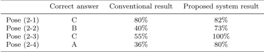
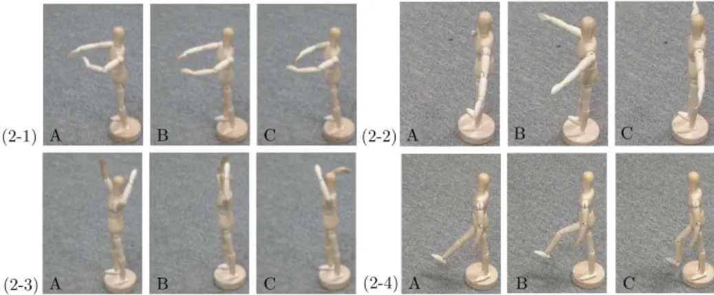
(16) 16. Fabian Lorenzo Dayrit et al.. Table 2: Pose matching results. Conventional and proposed system results refer to the rate of correct answers.. Pose Pose Pose Pose. (2-1) (2-2) (2-3) (2-4). Correct answer. Conventional result. Proposed system result. C B C A. 80% 40% 55% 36%. 82% 73% 100% 80%. tends to increase. Because the proposed system allows users to view the actor’s pose from wherever they want (see Fig. 11), they could choose to view it from the viewpoint that allows for the easiest estimation, i.e. from directly in front of the actor. We also note that for the proposed system, the MAE is higher for Poses (1-1) and (1-2) than for (1-3) and (1-4). We consider that this may be caused by the order of poses which are shown to users: group A users are shown Pose (1-1) first, then Pose (1-3), while group B users are shown Pose (1-2) first, then (1-4). This means that it takes some time to get used to our system. Pose matching. In the second part of experiments, users were tasked with discerning the actor’s pose. We formed four poses with a small mannequin and had the actor perform these poses, which we captured both with a conventional camera and our proposed system (Figs. 12 and 13). Similarly to the angle estimation, we captured the actor from different points of view in order to aid our texture selection, asking him to hold the pose as still as he could. For each of the four initial poses, we also formed two similar poses with the mannequin, shown in Fig. 14, making 12 poses in all. We alternately showed users the conventional image, and the AR reenactment. Users in Group A viewed Pose (2-1) and (2-2) using the conventional images and (2-3) and (2-4) using the proposed system, and users in Group B viewed the opposite. Users chose the closest pose from three mannequins’ poses (Fig. 14). We decided to let the users choose between mannequin poses because these would not contain cues, e.g. clothing folds, shadows, etc., that would relate them to the conventional image. Users were encouraged to view the AR reenactment from different viewpoints. Table 2 shows the results for this experiment. Users scored higher with our system than with conventional images for all poses. We consider that this is because the poses are not very discriminative from the frontal views that were shown to the users, while our system can provide side views.. 4.3 Survey We gave users a survey on the quality and applicability of the system, comparing it to the quality and applicability of our previous system [9]. First, users were shown the “Exercise” motion sequence rendered using our previous method, i.e., using cylinders for each body part, as in Fig. 15 (left). Users were then asked to answer the survey in Table 3. Next, users were shown the same sequence rendered using.
(17) Increasing Pose Comprehension through Augmented Reality Reenactment. (2-1). (2-4). (2-3). (2-2). 17. Fig. 12: Conventional images depicting the four poses that were shown to the users for pose matching.. (2-1). (2-2). (2-4). (2-3). Fig. 13: Poses in Fig. 12 viewed from the side.. (2-1) A. B. C. (2-2) A. B. C. (2-3) A. B. C. (2-4) A. B. C. Fig. 14: The mannequins to match the poses to. Correct answers are C for 1, B for 2, C for 3, and A for 4. our proposed method, as in Fig. 15 (right)2 . Users were then asked to answer the same questions a second time for the proposed system. The survey shows that while users were not entirely satisfied with the quality, they were positive toward the reenactment. The answers to Q1 shows that enough 2 A visual comparison of the two rendering http://yokoya.naist.jp/ fabian-d/arreenactment.htm. methods. can. be. found. at.
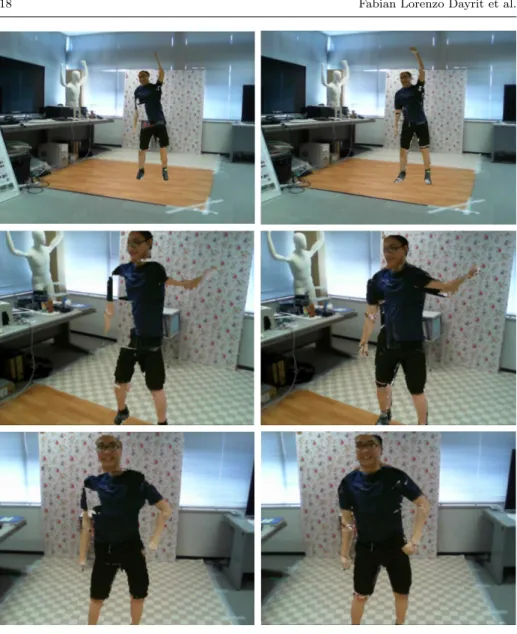
(18) 18. Fabian Lorenzo Dayrit et al.. Fig. 15: Left: “Exercise” sequence viewed with the previous, cylinder-based system. Right: The same frames viewed with the proposed system.. holes and artifacts exist in the rendering that they disturb the users’ experience of the previous system. These holes are the result of the rough 3D modeling of the target. The output quality has been improved for the proposed system by employing the state of the art body modeling method [18]. Q2 shows that most of the users thought that the motion was smooth enough, with the proposed system scoring higher. Q3 asks whether the synthesized reenactment looks like the original video. If viewed from the original capture point, it should strongly resemble the video since it is using the same video frames as textures. If viewed from elsewhere, however, it must be believable enough to look like it was captured from that.
(19) Increasing Pose Comprehension through Augmented Reality Reenactment. 19. Table 3: Survey, answers are from 1 (strongly disagree) to 5 (strongly agree). Question. Ave. ([9]). Ave. (proposed). 2.62 3.71 3.81. 3.86 4.29 4.24. I would prefer to watch the reenactment over the conventional video for... Q4 ...performances. 3.10 Q5 ...training videos. 4.05 Q6 ...sports recordings. 3.52 Q7 ...videos of daily life. 2.43. 3.62 4.57 4.05 3.29. Q1 Q2 Q3. I am not bothered by holes and artifacts in the reenactment. The reenactment’s motion is smooth. The reenactment resembles the conventional video.. viewpoint, and as the answers to Q3 show, most users felt that it accomplished this task, with the proposed system’s output being closer to the conventional video due to having a more accurate body model. Reactions to the listed applications were also positive. The highest-scoring application were training videos and sports recordings. Users scored our proposed system higher in all aspects compared to our previous system, which shows a marked improvement in quality. 5 Conclusion In this work, we have developed and implemented a system to capture human motion and show its virtualized motion. The process of capturing only requires a single RGB-D camera, which makes it easier for non-expert users. For showing the motion, the system synthesizes reenactments that can be viewed from arbitrary viewpoints using a mobile device. The reenactments are rendered by reconstructing the actor’s body parts using 3D mesh models and texturing them using the RGB video sequence. The reenactment’s virtual view is based on a map of feature points in the environment which we generate using visual SLAM during capturing and reuse in order to render the reenactment relative to its original capturing location. The reenactments are comprehensible by users and generally resemble the video they were based on. Users of the system are able to more precisely estimate body angles at any viewing angle. For cases involving ambiguous poses, the proposed system benefits the users by allowing them to view the pose from multiple angles. Its output quality is also higher, compared to our previous system. For future work, we would like to explore additional applications of the system. Users indicated that they would use the system for watching training videos, and we agree that the ability to watch a motion from any desired angle would be a boon to learners. Reducing the holes and artifacts in the output until it completely resembles a conventional video is another possible avenue of research. Acknowledgements This work was partially supported by JSPS Grant-in-Aid for Scientific Research Nos. 23240024 and 25540086.. References 1. de Aguiar, E., Stoll, C., Theobalt, C., Ahmed, N., Seidel, H., Thrun, S.: Performance capture from sparse multi-view video. ACM Trans. on Graphics 27(3) (2008).
(20) 20. Fabian Lorenzo Dayrit et al.. 2. Alexiadis, D.S., Zarpalas, D., Daras, P.: Real-time, full 3-D reconstruction of moving foreground objects from multiple consumer depth cameras. IEEE Trans. on Multimedia 15(2), 339–358 (2013) 3. Anderson, F., Grossman, T., Matejka, J., Fitzmaurice, G.: YouMove: Enhancing movement training with an augmented reality mirror. In: Proc. ACM Symposium on User Interface Software and Technology, pp. 311–320 (2013) 4. Azuma, R.T.: A survey of augmented reality. Presence 6(4), 355–385 (1997) 5. Beck, S., Kunert, A., Kulik, A., Froehlich, B.: Immersive group-to-group telepresence. IEEE Trans. on Visualization and Computer Graphics 19(4), 616–625 (2013) 6. Carranza, J., Theobalt, C., Magnor, M., Seidel, H.: Free-viewpoint video of human actors. ACM Trans. on Graphics 22(3), 569–577 (2003) 7. Castle, R., Klein, G., Murray, D.: Video-rate localization in multiple maps for wearable augmented reality. In: Proc. IEEE Int. Symposium on Wearable Computers, pp. 15–22 (2008) 8. Dai, B., Yang, X.: A low-latency 3D teleconferencing system with image based approach. In: Proc. ACM SIGGRAPH Int. Conf. on Virtual-Reality Continuum and Its Applications in Industry, pp. 243–248 (2013) 9. Dayrit, F.L., Nakashima, Y., Sato, T., Yokoya, N.: Free-viewpoint AR human-motion reenactment based on a single RGB-D video stream. In: Proc. IEEE Int. Conf. on Multimedia and Expo, 6 pages. (2014) 10. Debevec, P., Taylor, C., Malik, J.: Modeling and rendering architecture from photographs: A hybrid geometry- and image-based approach. In: Proc. ACM SIGGRAPH, pp. 11–20 (1996) 11. Hauswiesner, S., Straka, M., Reitmayr, G.: Image-based clothes transfer. In: Proc. IEEE Int. Symposium on Mixed and Augmented Reality, pp. 169–172 (2011) 12. Henderson, S., Feiner, S.: Augmented reality in the psychomotor phase of a procedural task. In: Proc. IEEE Int. Symposium on Mixed and Augmented Reality, pp. 191–200 (2011) 13. Hilsmann, A., Fechteler, P., Eisert, P.: Pose space image based rendering. In: Proc. Computer Graphics Forum, vol. 32, pp. 265–274 (2013) 14. Hondori, H., Khademi, M., Dodakian, L., Cramer, S., Lopes, C.V.: A spatial augmented reality rehab system for post-stroke hand rehabilitation. In: Proc. Conf. on Medicine Meets Virtual Reality, pp. 279–285 (2013) 15. Izadi, S., Kim, D., Hilliges, O., Molyneaux, D., Newcombe, R., Kohli, P., Shotton, J., Hodges, S., Freeman, D., Davison, A., Fitzgibbon, A.: KinectFusion: Real-time 3D reconstruction and interaction using a moving depth camera. In: Proc. ACM Symposium on User Interface Software and Technology, pp. 559–568 (2011) 16. Klein, G., Murray, D.: Parallel tracking and mapping for small AR workspaces. In: Proc. IEEE and ACM Int. Symposium on Mixed and Augmented Reality (2007) 17. Lorensen, W., Cline, H.: Marching cubes: A high resolution 3D surface construction algorithm. In: Proc. ACM SIGGRAPH, vol. 21, pp. 163–169 (1987) 18. Malleson, C., Klaudiny, M., Hilton, A., Guillemaut, J.Y.: Single-view RGBD-based reconstruction of dynamic human geometry. In: Proc. Int. Workshop on Dynamic Shape Capture and Analysis, pp. 307–314 (2013) 19. Matusik, W., Buehler, C., Raskar, R., Gortler, S., McMillan, L.: Image-based visual hulls. In: Proc. ACM SIGGRAPH, pp. 369–374 (2000) 20. Pag´ es, R., Berj´ on, D., Mor´ an, F.: Automatic system for virtual human reconstruction with 3D mesh multi-texturing and facial enhancement. Signal Processing: Image Communication 28(9), 1089–1099 (2013) 21. Shotton, J., Sharp, T., Kipman, A., Fitzgibbon, A., Finocchio, M., Blake, A., Cook, M., Moore, R.: Real-time human pose recognition in parts from single depth images. Communications of the ACM 56(1), 116–124 (2013) 22. Shum, H., Kang, S.B.: Review of image-based rendering techniques. Visual Communications and Image Processing pp. 2–13 (2000) 23. Velloso, E., Bulling, A., Gellersen, H.: MotionMA: Motion modelling and analysis by demonstration. In: Proc. ACM SIGCHI Conf. on Human Factors in Computing Systems, pp. 1309–1318 (2013) 24. Wang, Z., Ong, S., Nee, A.: Augmented reality aided interactive manual assembly design. The International Journal of Advanced Manufacturing Technology 69(5-8), 1311–1321 (2013).
(21) Increasing Pose Comprehension through Augmented Reality Reenactment. 21. 25. Waschb¨ usch, M., W¨ urmlin, S., Cotting, D., Sadlo, F., Gross, M.: Scalable 3D video of dynamic scenes. The Visual Computer 21(8-10), 629–638 (2005) 26. W¨ urmlin, S., Lamboray, E., Staadt, O., Gross, M.: 3D video recorder. In: Proc. Pacific Conf. on Computer Graphics and Applications, pp. 325–334 (2002) 27. Xu, F., Liu, Y., Stoll, C., Tompkin, J., Bharaj, G., Dai, Q., Seidel, H.P., Kautz, J., Theobalt, C.: Video-based characters: creating new human performances from a multiview video database. ACM Trans. on Graphics 30(4), 10 pages. (2011) 28. Yamabe, T., Nakajima, T.: Playful training with augmented reality games: case studies towards reality-oriented system design. Multimedia Tools and Applications 62(1), 259–286 (2013) 29. Ye, G., Liu, Y., Deng, Y., Hasler, N., Ji, X., Dai, Q., Theobalt, C.: Free-viewpoint video of human actors using multiple handheld Kinects. IEEE Trans. on Cybernetics 43(5), 1370–1382 (2013) 30. Zhang, Z.: A flexible new technique for camera calibration. IEEE Trans. on Pattern Analysis and Machine Intelligence 22(11), 1330–1334 (2000) 31. Zhou, Z., Shu, B., Zhuo, S., Deng, X., Tan, P., Lin, S.: Image-based clothes animation for virtual fitting. In: Proc. ACM SIGGRAPH Asia, 4 pages. (2012) 32. Zitnick, C., Kang, S., Uyttendaele, M., Winder, S., Szeliski, R.: High-quality video view interpolation using a layered representation. ACM Trans. on Graphics 23(3), 600–608 (2004).
(22)
図
+7
関連したドキュメント
We classify groups generated by powers of two Dehn twists which are free, or have no “unexpectedly reducible” elements.. In the end we pose similar problems for groups generated
We also describe applications of this theorem in the study of the distribution of the signs in elliptic nets and generating elliptic nets using the denominators of the
Key words: Benjamin-Ono equation, time local well-posedness, smoothing effect.. ∗ Faculty of Education and Culture, Miyazaki University, Nishi 1-1, Gakuen kiharudai, Miyazaki
In Section 3 the extended Rapcs´ ak system with curvature condition is considered in the n-dimensional generic case, when the eigenvalues of the Jacobi curvature tensor Φ are
Keywords: continuous time random walk, Brownian motion, collision time, skew Young tableaux, tandem queue.. AMS 2000 Subject Classification: Primary:
We present sufficient conditions for the existence of solutions to Neu- mann and periodic boundary-value problems for some class of quasilinear ordinary differential equations.. We
In Section 13, we discuss flagged Schur polynomials, vexillary and dominant permutations, and give a simple formula for the polynomials D w , for 312-avoiding permutations.. In
Analogs of this theorem were proved by Roitberg for nonregular elliptic boundary- value problems and for general elliptic systems of differential equations, the mod- ified scale of
