Sound Reproduction System With Adaptive Compensation of Temperature Fluctuation Effect
4
0
0
全文
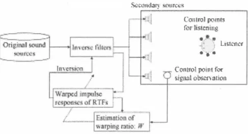
(2) おωf凶判「獄、utÇ;ç車. …iべl:,1. Cotrl.roi poi剤約 ぬr listenin皇 _ ,'_、 ,. i:. ). しぬi:ctíl't. 6淳、. COI.llrol point fQf. Sìlgl凶101絡釘、注tÎO'l. Fig. 1.. Con自guration of the proposed adaptive algorithm for the sound reproduction system. otherwise g(凧W) is g附n by. where αis a step-size parameter. In the second term on the right-hand side of Eq. (7), the partial differentiation is given by. ( �-1. 一. jb =. 伽,W) =古{乞G(k)eJ結m 2::. +. 仰併. 一d占(何π刈)け} 2 2ε:{何d(加例n吋)ト. 一90 。。. 最{. (3). _;:-1. 九一 目. + +一. W. G(叩 {_;:-1 [å� j )H(収(k)]} J åW. (4). where To is the original room temperature and Tt is the room temperature after fluctuation at time t. \ '-' .. ,-- \" r-\ '". wh巴re. 2-G(k,W). θW. 2.3. A daptive A lgorithm for Warping Ratio Estimation. � テG(内m. 也巴 = :T θW N 1 L--. k=号. (. ). l. + E 仰刷仰)μEJ 2工斗ヰ指併i持栴叫糾4品保元子立 k=N-¥. j. In practice,白隠しthe adaptation algorithm is performed at a particular control point for eπor observation. Next, the warping ratio obtained by the aJgorithm is applied to other control points at which their reproduced signals are not observed by the sys tem, Using the above-mentioned procedure, we can compensate the temperature fluctuations at all controJ points.. oo qべU 可li. α. w w 一W h. W. 一 一. +. W. (7). k )m l W2N jr. h ( :N. 伽一 明. e. Using the squar巴d eπor and the i-th warping ratio 11パz), the(i+l)ーth wa中ing ratio W(i+l) can be updated by th巴 steep 巴st d巴scent method, as shown below:. j出. W一 h一. X(k). J. 日開. (k). J. .. otherwiseδg(m,W)jθW can be given by. where. (6). ". G. d(n) = ;:-1 {G(k,W)H(k)X(k)} ;:-1 {. } denotes the inverse DFT operator. G(k, W) is G(k) wa中ed w油wa巾ng ratio W, H(k) is the inverse filter of G , and is the input signal of the system. (9). (. GW併m +ル ゐ:...l...-. (5). and. ;:{恭仇. where;: {・} denotes the D打ope削or. If W(i) is greater than or equal to 1, the partial differentiationθg(m,W) jθW inEq. (9) is given by. M 1一. e=乞{ d(η)一d(η)} 2,. d(n. (8 ). ) ハU l. d(rπ1). ,. 義;: {g(m, W)}. 日 Z M T fitτ …. The theoretical warping ratio is defined by two t巴mperature val ues, as shown inEq. (4). However, the compensation of impulse responses of RTFs based on this value cannot be guaranteed to be suitable because there are bias and e町ors m白e measur巴ment of temperature using thermometers. Each thermometer shows the temp巴rature at only one point in the room, and temp巳ra時 tures in the transfer channel of sound are not always uniform. Therefore, in this section, we propose an automatic method of estimating the warping ratio using the observed signal from a microphone placed at only one of the control points In this method, the warping ratio that minimizes th巴 squared error巴between observed s剖19na必1 and estimated signal lβs sought. The squarl閃巴d eπor is defined as. [G(k,W)H(k)X(刈}. 22::{d(n)一ct(η)}. The theoretical value of the warping ratio is defined as the ratio of two sound speeds. e. 2 ε {μ何川d(仰(何仲η.
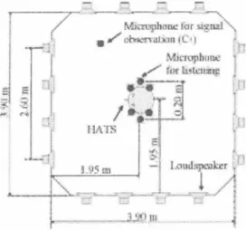
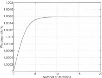
(3) The impulse respons巴s are measured before and after tem perature fluctuation. Here, we attempt to warp from the im pulse responses ofRTF, TFa, which were measured at 29.20C to those of RTF, TFb, which were measured at 28. 1 oc. A lthough the theoretical value of the warping ratio W is calculated to be 1.00161 using Eq. (4), lhe compensation of RTF based on this value cannot be guaranteed to be suitable because there are bias and eπors in the measllrement of temperature. A ccord ingly, we search for the suitable warping ratio by the proposed method. Herea仇er, we define TF� as TFa warped by the theo retical warping ratio ofTFa, and TF� as the TFα warped by the suitable warping ratio of TF.αー 3.2. Inverse Filter Design. Fig. 2. Layout of acoustic experiment r∞m.. ぐa. c吾首.:. (�. ・一事/ffA-m. ro 伽 到陵町 _...- M îc. C. CErn. Fig.3. A 汀angemenl of microphones.. Table 1Measurement conditions of impulse responses. TSP signal lenglh sampling frequency quantizatio叩 addition for averaging. I I I I. 131072 points 48∞OHz 16 bits 4 times. Using the impulse responses TFo, TFa, TF�, and TF�, we dc sign inverse filters for the multichannel sound reproduction sys tem. The inverse filters are designed by lhe least-norrn solution (LNS) in the frequency domain [3). The impulse responses, in which lhe signal length is 7200 points, are transforrned into the frequency domain by FFT with a length of 32768, and in verse filters are deterrnined. These inverse filters are filtered by a band-pass filter in which the passband range is 150-10000 Hz, and are then transforrned into the time domain by a 32768・pOlOt inverse FFT We define白inverse filters ofTFo, TFα, TF�, and TF� as INV o, INVα, INV�, and INV�, respectively. .. 3.3.. The proposed algorithm searches for the warping ratio using the only observed signal at C7・ We apply the warping ratio at C7 to出e compensation of temperature !luctllation at other control points (Cj-C6). Hence, we perforrn the supervised adaptalion at only C7. In contrast, we戸rforrn lhe unsupervised adaptation at other control points. The initial solution of the warping ratio is set to be 1.00000, and the process is repeated 20 times. The step-size parameterαshown in Eq. (7) is 0.00∞ 1, which is obtained empirically. The input signal of system X(k) is an impulse response of lhe band-pass filter the passband range of which is 150-10000 Hz. 3.4.. 3. NUMERICAL EVALUATION. To investigate lhe effect of lhe proposed adaptive algorithm for the sound reproduction system, we evaluate the signal-to-noise ratio (SNR ), which represents lhe repr<吋ucuon accuracy, USlOg lhe impulse responses measured in a real acoustic environment. In出is paper, we assume that lhe number of secondary acoustic sources of lhe reproduclion syslem is 16, lhe number of control poinls for listening is six, and lhe number of control points for signal observation is one. 3.1.. Measurement of Impulse Responses. in Table 1.. Experimental Results. Figure 4 shows the behavior of the updated warping ratio in the iterative adaptation. This result indicates that the warping ratio converges at about 1.00158. The relationship between the number of iterations and squared eπor from the desired signal is shown in Fig. 5, where the solid line indicates the eπor observed at C7, and the dashed line indicates the averaged eπor observed at Cj-C6・ The squared e汀or e is defined by Eq. (5). These results show that the 巴汀ors are found to converge monotonically at all control points, and are reduced by about 18-19 dB. This result reveals lhat th巴 unsup巴rvised adaptation can be achieved by the proposed algorithm, and although the convergence of this algorithm is not guaranteed, it could be proved experimentally. Figure 6 shows the SNR s. The SNR is defined as SNR. [dB]. =. 10 log. εηId(n)12 Ln Id(π) - d(n)12. ( 12). where d(n) is the observed signal and d(n) is the desired sig nal. Before the warping process, the SNR at C7, which is the contol point for signal observation, is 5.7 dB. A fter the warp ing process by the proposed method, the SNR was improved by 17.4 dB. On the other hand, the improvement of the averaged SNR at Cj-C6 is 16.9 dB. In order to compare the differencc of warping ratios, the SNR s by the theoretical warping ratio is also shown in Fig. 6. From these results, there is almost no dif二 ference between these warping methods. These results indicatc that we can realize a high-quality sound reproduction system using this adaptation algorithm.. 口叫d qべu 旬。A. The impulse responses used in lhis study are measured in an acoustic experiment r∞m, in which lhe reverberation Lime is about 0.15 seconds. The layout of the experiment r∞m is shown in Fig. 2. Four loudspeakers as secondary sources are placed in each wall. Head and torso simulator (HATS) is placed at the center of the region surrounded by loudspeakers. Six posト tions (Cj-C6), at two ears of the HATS and 0.05 m in front and behind them, are selected as control points at which the micro・ phones are set, as shown in Fig. 3. The microphone for signal observation (C7) is自xed at the posiLion 1.50 m from HATS cen ter 60 degrees to the right from the face front of HATS. Time stretched plllse (TSP) [8) was used as the sOllnd source signal for measuremenl. The measurement conditions are listed. Numerical Condition.
(4) 4. CONCLUSIONS. We described a m巴thod for compensating temperature fluctua tion by Iinear time warping to avoid出e degradation of repro duction accuracy of a sound reproduction system. We proposed an adaptive aJgorithm for warping ratio estimation. In numer ical simulation using real environmental data, we can improve the reproduction accuracy at each control point by about 17 dB, in which a difference in temperature is 1.loC. In this study, we assume that the distribution of tempera ture is uniform everywhere in the room, however, the distribu・ tion of the room temperature is not uniform in出e real environ ment. Therefore, we must further investigate the performance of the proposed algori出m asumming various temperature dis tributions. 1.002 1.001B 1.0016 1.0014 ?:! 。1.0012 '". Z. 四1.001. E. ;;; 1.000B ?:!. This work was pa口Iy supported by CR EST (Core R esearch for Evolutional Science and Technology) in Japan.. 5. 。. A cknowledgements. 20. 15. 10. Number 01 iterations. Fig. 4. R elationship between the number of iterations and the. warpmg ratlo.. REFERENCES. [4] S. J. Elliott, I. M. Stothers and P. A. Nelson, "A multiple 巴汀or LMS algorithm and its application to出巴 actlve con司 tro1 of sound and vibration, " IEEE Trans. ASSP, Vo1. 35, No. lO, 1987, pp. 1423-1434. [5] T. Hikichi and F. Itakura, '寸ime variation of room acous tic transfer functions and its effects on a mu1ti-microphone d巴reverberation approach, " Workshop on Microphone Ar rays: Theory, Design & Application, CAlP, 1994.. -. [3] A. Kaminuma, S. Ise and K. Shikano, "A method of de signing inverse system for multi司channel sound reproduc tion system using 1east-norm-so1ution, " Proc. of Active99, Vo1.2, 1999, pp.863-874. -6. -. [2] M. Miyoshi and Y. Kaneda, "Inverse filtering of room acoustics, " IEEE Trans. ASSP, Vo1.36, No.2, 1988, pp.145-152.. au nu qζ 41 41 {国 司 }』 ロヒ 凶. [ 1] 1. Bauck and D. H. Cooper, "Generalized transaural stereo and applications, " J. Audio Eng.Soc., Vol.44, NO.9, 1996, pp.68 3-705. 一一Microphone lor signal 0凶e刊ation (C7) ーーーCo明trol points (Cl-C6). ー14 ー16. -20L O. [8] Y. Suzuki, F. Asano, H. -Y. Kim, and T. Sone, "An op timum computer-generated pulse signa1 suitable for the measurement of very long impulse responses, " J. Acoust Soc.Am., Vo1.97, No.2, 1995,pp.1119-1 123. 10. Number 01 iterations. 15. 20. squared eπor. 30 25 20. Proc. of The seventh Western Pacがc RegionaL Acoustics. [7] Y. Tatekura, H. Saruwatari and K. Shikano, "Compen sation of Temperature Auctuation in Inverse System of Sound Field R eproduction by Linear Warping Process ing, " Proc. of the 1刀h International Congress on Acous tics (ICA2001人3P.05, 2oo l .. 5. Fig. 5. R elationship between the number of iterations and the. [6] A. Kaminuma, S. Ise and K. Shikano, "R obust sound reproduction-system design against the head movement," Conference (WESTPRAC VII) , Vol. J , 2∞0, pp.489-492.. 、 、 、 一ー 司ーー-ーーーーーーーーーーーーーーーーーーー. -18. 白 て3. c: Z ({). 15 10. B111 1111 .111 JII .目 1. 1. 11里RSthird l 1111固 Fig. 6. Comparison of the reproduction accuracy at each control. point before and after warping by the adaptive method.. ハU A斗&.
(5)
図
関連したドキュメント
It is suggested by our method that most of the quadratic algebras for all St¨ ackel equivalence classes of 3D second order quantum superintegrable systems on conformally flat
At the same time, a new multiplicative noise removal algorithm based on fourth-order PDE model is proposed for the restoration of noisy image.. To apply the proposed model for
Keywords: continuous time random walk, Brownian motion, collision time, skew Young tableaux, tandem queue.. AMS 2000 Subject Classification: Primary:
By the algorithm in [1] for drawing framed link descriptions of branched covers of Seifert surfaces, a half circle should be drawn in each 1–handle, and then these eight half
We use the monotonicity formula to show that blow up limits of the energy minimizing configurations must be cones, and thus that they are determined completely by their values on
While conducting an experiment regarding fetal move- ments as a result of Pulsed Wave Doppler (PWD) ultrasound, [8] we encountered the severe artifacts in the acquired image2.
approah, whih is based on a step by step onstrution of the walks [6, 5℄.. We repeat in Setion 3 the proof
Hence, for these classes of orthogonal polynomials analogous results to those reported above hold, namely an additional three-term recursion relation involving shifts in the
