of Nanostructured TiNi Alloys Processed by
High-Pressure Torsion
著者
AWANG SHRI Dayangku Noorfazidah Binti
year
2014
その他のタイトル
高圧ねじり加工で作製したナノ構造TiNi合金の表面
評価と生体適合性
学位授与大学
筑波大学 (University of Tsukuba)
学位授与年度
2014
報告番号
12102甲第7097号
URL
http://hdl.handle.net/2241/00126608
Surface Characterization and Biocompatibility of
Nanostructured TiNi Alloys Processed by High-Pressure
Torsion
Dayangku Noorfazidah Binti AWANG SHRI
Doctoral Program in Materials Science and Engineering
Submitted to the Graduate School of
Pure and Applied Sciences
in Partial Fulfillment of the Requirements
for the Degree of Doctor of Philosophy in
Engineering
at the
i
Acknowledgements
First and foremost, all praise to Allah S.W.T for taught the mankind what they did not know.
I am deeply grateful to my supervisor Prof. Koichi Tsuchiya, for his guidance, vision and support throughout the course of my PhD work. I could not have asked for a better one, his continuous advice and encouragement have been very valuable to me. The dedication and care he provided to me during my PhD are qualities that I hope to be able to carry with me.
I would like to extend my warmest gratitude to Dr Akiko Yamamoto from Biometals Group in National Institute for Materials Science (NIMS) for giving me the opportunity to study biomaterials and corrosion in her lab. Her guidance and constructive comments is proven to be very helpful in order for me to finish this thesis.
I would also like to thank my thesis examiner; Prof Yoshio Sakka and Prof Hee Young Kim for their time and input into this thesis.
Many thanks to members in Microstructure Design Group: Dr. Seiichiro Ii, Dr. Satoshi Emura, Dr. Xiaohua Min, Dr. Alok Singh, and Dr. Julian Rosalie and Yoshimi Toyono for their support during my experiments and encouragement whenever I was in need. My gratitude is also given to my fellow friends: Dr Fanqiang Meng, Baozhen Jiang, Tiantian Li, Haotian Ni, Xuejiao Chen and Ji Xin for making the three years of my life in Tsukuba easier. I also would like to thank members in Biometals Group: Yuko Kohyama, Akemi Kikuta and Noriko Moriguchi.
I am personally indebted to many kind souls during my journey in finishing my PhD here in University of Tsukuba. I wish to express my loving gratitude to my Japanese sister, Mrs Tomomi Utagawa, who has helped me getting through with my life since day one. I would also like to
ii
acknowledge all my close friends that have been supporting me during my study. Thank you Mohd Muzamir Mahat, Ramli Junid, Agnieszka Witecka, Nor Akmal, Livia Lahat, Fauziana, Amir and Gaulthier for being there for me during good and bad time.
Last but not the least; I want to thank my family: my mother Hajah Aishah Abdullah and my father Hj Awang Shri Awang Putra, my brother, Awangku Nazrulddin and my sister, Dayangku Noor Zafirah for their love and support has always been the drive for me to finish my PhD. Thank you for helping me to get to where I am today.
iii
Table of Contents
Acknowledgements ... i
List of Figures ... vii
List of Tables ... x
Chapter 1 Introduction ... 1
1.1 TiNi Alloys ... 1
1.2 Biomaterials ... 3
1.2.1 Biomaterial and surface interaction ... 4
1.2.2 Protein adsorption ... 5
1.3 Surface Characterization ... 6
1.3.1 Surface characterization ... 6
1.3.2 X-ray Photoelectron Spectroscopy ... 6
1.4 Corrosion in biomaterial ... 8
1.4.1 General concept of corrosion ... 9
1.4.2 Corrosion resistance of TiNi alloys ... 11
1.4.3 Ni ion release ... 12
1.5 Severe plastic deformation... 12
1.5.1 Equal-channel angular pressing (ECAP) ... 13
1.5.2 Accumulative roll bonding (ARB) ... 13
1.5.3 Multi-directional forging (MDF) ... 14
iv
1.5.5 Parameter in estimating the strain in HPT ... 16
1.6 Research objectives ... 18
1.7 Thesis outline ... 18
1.8 References: ... 19
Chapter 2 Phase Analysis and Mechanical Properties Characterization of TiNi Deformed by High Pressure Torsion ... 23
2.1 Introduction... 23 2.2 Experimental Procedures ... 24 2.2.1 Material preparation... 24 2.2.2 Material characterization... 24 2.3 Results ... 25 2.3.1 Structural Evolution ... 25 2.3.2 Mechanical properties ... 27 2.4 Discussion ... 27 2.5 Conclusion ... 29 2.6 References ... 30
Chapter 3 Biocompatibility of Nanostructured TiNi Processed by High-Pressure Torsion .... 31
3.1 Introduction... 31
3.2 Experimental Procedures ... 32
3.2.1 Material preparation... 32
3.2.2 Cell cultures ... 32
3.2.3 Cytocompatibility Evaluation... 32
3.2.4 Nickel ion release ... 33
3.2.5 Protein adsorption analysis ... 33
v
3.3.1 Colony formation and morphology ... 35
3.3.2 Ni ion release ... 37
3.3.3 Protein adsorption behavior ... 37
3.4 Discussion ... 40
3.4.1 Effect of HPT on the colony formation behavior ... 40
3.4.2 Suppression of Ni ion release by HPT deformation ... 40
3.4.3 Effect of HPT on the protein adsorption behavior ... 41
3.5 Conclusion ... 42
3.7 References: ... 43
Chapter 4 Surface characterization of HPT deformed TiNi alloys ... 45
4.1 Introduction... 45
4.2 Experimental method ... 46
4.2.1 Sample preparation ... 46
4.2.2 X-ray photoelectron spectroscopy ... 46
4.3 Results ... 47
4.3.1 Surface characterization of Ti-50mol%Ni ... 47
4.3.2 Surface characterization of Ti-50.9mol%Ni ... 59
4.4 Discussion ... 67
4.4.1 Effect of HPT on the surface composition of TiNi ... 67
4.4.2 Effect of HPT on the TiNi passive film formation ... 68
4.4.3 Effect of cell culture to the passive film in TiNi ... 71
4.5 Conclusion ... 71
vi
Chapter 5 Electrochemical Characterization of TiNi alloys Deformed by High Pressure
Torsion ... 75 5.1 Introduction... 75 5.2 Experimental Methods... 76 5.2.1 Sample preparation ... 76 5.2.2 Electrochemical measurements ... 76 5.3 Results ... 77 5.3.1 OCP Measurement ... 77 5.3.2 Polarization curves ... 78 5.4 Discussions ... 81 5.5 Conclusion ... 84 5.6 Reference ... 85 Chapter 6 Conclusions ... 87
vii
List of Figures
Fig. 1.1 Schematic illustration of the crystal structure of TiNi (a) B2 cubic unit cell of austenite and (b)
B19’ monoclinic unit cell. ... 1
Fig. 1.2 Schematic representation of the shape memory effect of TiNi alloy [2]. ... 2
Fig. 1.3 Schematic representation of the superelasticity effect of TiNi alloy [2]. ... 3
Fig. 1.4 Surface properties governing behavior of implanted material [8]. ... 4
Fig. 1.5 Schematic representation of the process of protein adsorption on a solid surface [14]. ... 6
Fig. 1.6 An electron energy diagram for a Ni2+ showing the absorption of a photon and resultant expulsion of a 2p level photoelectron. ... 8
Fig. 1.7 Influence of fibroblast on the corrosion of biometallic material [37]. ... 12
Fig. 1.8 Schematic of ECAP process [48] ... 13
Fig. 1.9 Schematic of ARB process [49]. ... 14
Fig. 1.10 Schematic of MDF process [50]. ... 14
Fig. 1.11 Schematic illustration of HPT processing [52]. ... 16
Fig. 1.12 Parameters used in estimating the total strain in HPT. ... 17
Fig. 2.1 Schematic illustration of microhardness testing along the radial of the sample. ... 24
Fig. 2.2 (a) X-ray diffraction patterns of Ti-50mol%Ni before and after HPT deformation and (b) its corresponding FWHM at 2θ ~ 42º... 25
Fig. 2.3 (a) X-ray diffraction patterns of Ti-50.9mol%Ni before and after HPT deformation and (b) its corresponding FWHM at 2θ ~ 42º... 26
Fig. 2.4 Micro-hardness of (a) Ti-50mol%Ni and (b) Ti-50.9mol%Ni before and after deformation with different turns as a function of distance from the disk center. ... 27
viii
Fig. 2.5 Schematic illustration of the nanostructures of HPT deformed TiNi as observed by TEM
showing the nanograins (black) and amorphous (gray)region [17]. ... 29
Fig. 3.1 Giemsa-stained samples showing the colony on the Ti-50mol%Ni samples surfaces. ... 33
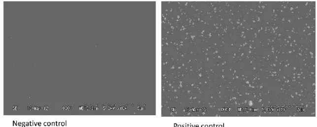
Fig. 3.2 SEM images of BHPT Ti-50mol% showing the negative and positive control. ... 34
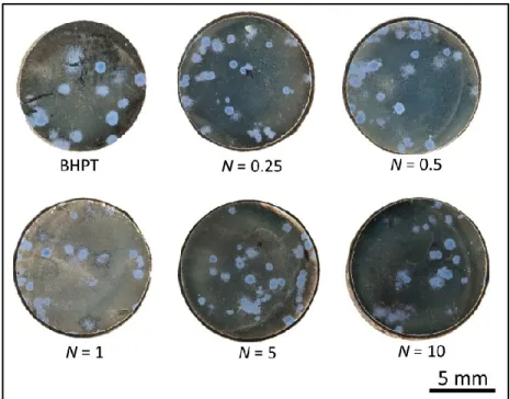
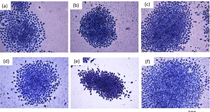
Fig. 3.3 Representative image showing colony morphology formed on the surface of (a) BHPT (b) N = 0.25 (c) N = 0.5, (d) N = 1, (e) N = 5 and (f) N = 10 Ti-50mol%Ni samples ... 36
Fig. 3.4 Representative image showing colony morphology formed on the surface of (a) BHPT (b) N = 0.25 (c) N = 0.5, (d) N = 1, (e) N = 5 and (f) N = 10 Ti-50.9mol%Ni samples ... 36
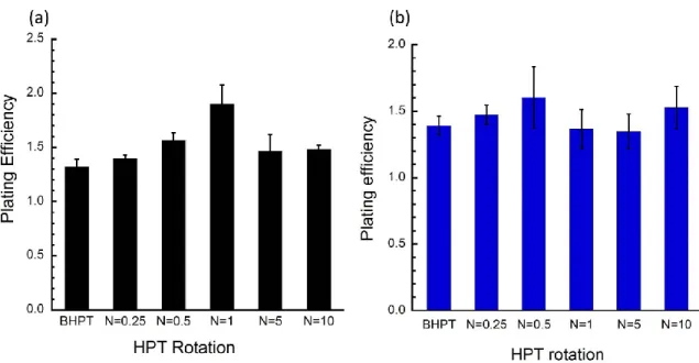
Fig. 3.5 Plating efficiency of (a) Ti-50mol%Ni and (b) Ti-50.9mol%Ni. ... 37
Fig. 3.6 Ni ion release from (a) Ti-50mol% Ni and (b) Ti-50.9mol%Ni as a function of HPT rotation. ... 38
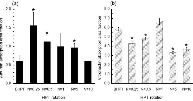
Fig. 3.7 (a) Albumin and (b) vitronectin adsorption on Ti-50mol%Ni as function of HPT rotation... 39
Fig. 3.8 (a) Albumin and (b) vitronectin adsorption on Ti-50.9mol%Ni as function of HPT rotation. ... 39
Fig. 4.1 A representative survey XPS spectrum of (a) BHPT 50mol% Ni and (b) BHPT Ti-50.9mol%Ni. ... 48
Fig. 4.2 Deconvolution of C1s peak on Ti-50mol% BHPT sample. ... 50
Fig. 4.3 Series of C1s peak of Ti-50mol%Ni (a) before and (b) after cell culture. ... 51
Fig. 4.4 Deconvoluted spectra of Ti 2p region of Ti-50mol%Ni BHPT sample. ... 52
Fig. 4.5 Deconvolution spectra of O 1s region of Ti-50mol%Ni BHPT sample. ... 52
Fig. 4.6 Series of O1s peaks of Ti-50mol%Ni (a) before and (b) after cell culture. ... 53
Fig. 4.7 Series of Ni 2p peaks of Ti-50mol%Ni (a) before and (b) after cell culture. ... 54
Fig. 4.8 Ratio of (a)Ti[Me] / Ti[Ox] and (b) Ni[Me] /Ni[Ox] as function of HPT rotation of Ti-50mol%Ni . .... 55
Fig. 4.9 Series of N 1s peaks of Ti-50mol%Ni after cell culture. ... 57
Fig. 4.10 Depth profile for (a) BHPT, (b) N = 0.25 and (c) N = 0.25 before cell culture. ... 58
Fig. 4.11 Depth profile for (a) BHPT, (b) N = 0.25 and (c) N = 0.25 after cell culture. ... 58
Fig. 4.12 Series of C 1s peaks of Ti-50.9mol%Ni (a) before and (b) after cell culture. ... 62
Fig. 4.13 Series of O1s peaks of Ti-50.9mol%Ni (a) before and (b) after cell culture. ... 63
Fig. 4.14 Series of Ni 2p peaks of Ti-50.9mol%Ni (a) before and (b) after cell culture. ... 64
Fig. 4.15 Series of N 1s peaks of Ti-50.9mol%Ni after cell culture. ... 66
Fig. 4.16 Depth profile of Ti-50.9 mol%Ni for (a) BHPT, (b) N = 0.25 and (c) N = 0.25 before cell culture. ... 67
Fig. 4.17 Ratio of proportion of the metallic Ni to metallic Ti on the film oxide of Ti-50mol%Ni as the function of HPT rotation. ... 68
Fig. 4.18 Schematic illustration of passive film formation. ... 70
ix
Fig. 5.2 Open circuit potential of (a) Ti-50mol%Ni and (b) Ti-50.9 mol%Ni in cell culture media... 79 Fig. 5.3 The potentiodynamic polarization of (a) Ti-50mol%Ni and (b) Ti-50.9 mol%Ni in cell culture media. ... 79 Fig. 5.4 Surface morphologies of (a) microcystalline (b) amorphous and (c) nanocrystalline Ti-50.2mol%Ni after corrosion in Hank's solution [10]. ... 83
x
List of Tables
Table 2.1 Degree of torsional deformation with different number of revolutions (edge of sample) ... 27 Table 4.1 Chemical composition of the Ti-50 mol%Ni surface samples as measured by XPS ... 49 Table 4.2 Chemical composition of the Ti-50 mol%Ni surface samples as measured by XPS after cell culture ... 49 Table 4.3 Summary of contribution for each species from Ti-50mol% O1s and C1s spectra before and after cell culture... 56 Table 4.4 Chemical composition of the Ti-50.9mol%Ni surface samples as measured by XPS ... 60 Table 4.5 Chemical composition of the Ti-50.9mol%Ni surface samples after cell culture as measured by XPS... 60 Table 4.6 Summary of contribution for each species from Ti-50mol% O1s and C1s spectra before and after cell culture... 65 Table 5.1 Corrosion parameter of Ti-50mol%Ni ... 80 Table 5.2 Corrosion parameter of Ti-50.9mol%Ni ... 80
1
Chapter 1 Introduction
1.1 TiNi Alloys
Titanium nickel (TiNi), an intermetallic compound, was discovered by metallurgist Willian J. Buehler at the Naval Ordinance Laboratory. The unique properties of an equiatomic TiNi alloys was discovered when he observed the major change in the atomic structure of the material due to temperature change [1]. The shape memory effect and superelasticity of TiNi alloys is attributed to its ability to exist in two different temperature-dependant phases: austenite and martensite. The high temperature austenite parent phase, stable under low stress is in cubic form with B2 structure. The low temperature martensite phase, stable under suitably higher stress condition, is monoclinic with B19’ structure. Fig. 1.1 illustrates the crystal structure of B2 and B19’.
Fig. 1.1 Schematic illustration of the crystal structure of TiNi (a) B2 cubic unit cell of austenite and (b) B19’ monoclinic unit cell.
2
Fig. 1.2 Schematic representation of the shape memory effect of TiNi alloy [2].
The inherent ability of this alloy to alter their type of atomic bonding which causes unique and significant changes in mechanical properties and crystallographic arrangement is termed as superelasticity and shape memory effect. This changes, occurs as results of martensitic transformation, as a function of temperature and stress.
The mechanism of the shape memory effect is described as follows. Upon cooling, the austenite phase starts to transform to martensite at Ms (martensite start temperature). Since the martensite phase has lower symmetry than the austenite phase, martensites with the same structure but in different crystallographic orientations (called variants of martensite) can be formed. For example, in B2 (cubic) to B19’ (monoclinic) transformation of Ni-Ti alloy, as many as 12 correspondence variants can be formed. Formation of martensite in the parent phase will cause a large strain due to the fact that the martensitic transformation is associated with a shape change. A combination of two or four variants may form in tandem to reduce this strain and this particular morphology is called self-accommodation. Variants in this morphology are twin-related to each other. Twins introduced upon martensitic transformation can act as a deformation mode if a stress is applied, since the twin boundary in Ni-Ti is mobile. This process is called detwinning as a favorably oriented variant grows at the expense of other less favorable ones. The deformation remains when the stress is released. Upon heating, the martensite variants revert to their original orientations in the austenite phase so that the original shape is restored. Ordinarily the shape memory effect is one-way as only the shape of the austenite phase is memorized.
Superelasticity at high temperatures is essentially due to a stress-induced martensitic transformation. When the SMA sample is at a temperature above Ms, in which the austenite phase is the dominant phase in a stress-free specimen, the martensite phase can be induced by application of an outer force. Once the
3
stress is released, the martensite is unstable at high temperature, thus the reverse transformation happens and the strain is recovered. The high elasticity of NiTi is not simply stretching the atomic bonds, but it is the result of changes in the crystal structure by stress.
Fig. 1.3 Schematic representation of the superelasticity effect of TiNi alloy [2].
The superelasicity and shape memory effect of TiNi alloys made it one of the common metals used in the biomedical application such as orthodontic archwires, stents and guidewires. Superelasticity of TiNi alloys allows for the use as archwires as it can exert light and constant force on top of good mechanical properties and corrosion resistance [2,3]. For the usage as stent, TiNi stents are self-expanding, taking advantage of their shape memory capabilities. Their superelasticity allows for the delivery of stents to the intervention site without kinking or permanently deforming [4].
1.2 Biomaterials
Another consideration in the usage of TiNi alloys as medical devices is its biocompatibility. A biomaterial was defined by American National Institute of Health "as any substance (other than a drug) or combination of substances, synthetic or natural in origin, which can be used for any period of time, as a whole or as a part of a system which treats, augments, or replaces any tissue, organ, or function of the body" [5]. Since this definition excludes application such as orthodontic brackets and surgical instruments, the most appropriate definition for a biomaterials is proposed by D. F William as "material intended to interface with biological system to evaluate, treat, augment or replace any tissue, organ or function of the body" [6].
Biocompatibility is described as "the ability of a material to perform with an appropriate host response in a specific application"[6]. In order for a material to be deemed suitable for biological application, it must be fulfilled several requirements. The materials should be able to perform its biological requirement without causing any cell death, chronic inflammation or other damage of cellular or tissue function [7]. Besides the structural requirement, the biocompatibility also plays a crucial roles as the its surface is directly exposed to the living organism.
4 1.2.1 Biomaterial and surface interaction
The interaction between metal surfaces and tissues is a complex matter. In the long term, metal ions release from the surface and specific biological activity of these metal ions may affect the tissue adjacent to the metal implants. To understand the implication of the metal used as biomaterials, we have to first understand the interaction between biological environments with the material.
The outermost atomic layer of general biomaterial surface at the moment of insertion in to the tissue is a combination of inorganic or organic oxides and hydroxides with low chemical reactivity and low solubility at physiological conditions. Different surfaces possess different basic water chemistries as represented by their elemental compositions and functionalities, such as –OH, −CH3, PO4, −NH2, −COOH, and −SiOH groups. This chemistry also gives rise to different free surface energies, water-retaining capacities, surface mobility, and other properties that may or may not be important for blood and tissue responses. Fig. 1.4 summarizes a few important surface chemical and physical properties believed to be relevant to in vivo behavior of biomaterials [8].
Fig. 1.4 Surface properties governing behavior of implanted material [8].
Biocompatibility of a material surface is closely related to the response of cells in contact with the surface and their adhesion. The initial response to a material placed in a biological environment is the adsorption of the water molecules. The extent and specific manner of interaction of the water molecules with the surface is dependent on the surface properties. These properties also determine the adsorption behavior of protein and other molecules. Within seconds to hours after implantation, adsorbed layer of protein covers the material surface. Then, the cells eventually reach the surface and interact with the surface through the protein layer [9]. Cellular responses are always mediated through proteins via their
5
ligands [10]. The cells can adhere, release active compounds, recruit other cells, grow in size, replicate or die depending on their interaction with the adsorbed protein [11].
1.2.2 Protein adsorption
Proteins are essential parts of organisms and involve in many essential processes within cells. Proteins are organic macromolecules built up from 20 different amino acids linked together by peptide bonds. Proteins are responsible for various functions such as forming part of extracellular matrix (ECM) for structural and mechanical support, cell signaling, and immune response and cell adhesion. Protein adsorption is a highly complex process. Protein adsorption can only take place if the Gibbs energy of the system decreases [12,13]. Proteins are surface-active and tend to accumulate at interfaces between the solid surface and liquid. Fig. 1.5 shows the schematic explanation of individual steps involved in the adsorption process of a protein molecule. The process and mechanism of protein adsorption and desorption can be explained as follows:
1. The protein molecules are transported from the solution towards the surface by diffusion and convection, influenced by solid surface electrostatic potential.
2. Protein attachment is driven by the decrease of the Gibbs energy in the system. The attachment of the proteins on the surface is influenced by their amino acid composition, size and their overall physical and chemical properties. The proteins also may change in structure upon adsorption
3. Interaction between the protein and surface might further alter the proteins’ structure.
4. Desorption and the diffusion back into the solution might occurs although it is less probable due to high number of interaction points with the surface and a more stable binding after protein unfolding.
6
Fig. 1.5 Schematic representation of the process of protein adsorption on a solid surface [14].
Albumin is one of the most popular proteins in the human blood plasma while vitronectin is one of the key proteins for cell attachment onto the substrate surface in vitro cell culture condition.It is reported that albumin adsorption onto a material surface reduces the pro-inflammatory activity of macrophage [15] and platelet-activated thrombogenesis [16]. Vitronectin is a glycoprotein present in plasma mediating cell adhesion to a substrate surface [17] and reorganizing cytoskeleton [18].
1.3 Surface Characterization
1.3.1 Surface characterization
Key factors in determining good compatibility between the material and the host tissue are surface wettability, roughness, chemical composition, electric charge and mobility, and corrosion resistance [19]. Atoms on the surface are mostly highly unstable leading to enhanced mobility and higher reactivity. These surface atoms can easily undergo phase transformation, segregation or even dissolution (corrosion). Thus, surface characterization of the biomaterial is important in determining its biocompatibility.
1.3.2 X-ray Photoelectron Spectroscopy
X-ray photoelectron spectroscopy (XPS) is a standard tool used in characterizing the biomedical surface. XPS method is based upon the photoelectric effect in which soft X-rays are used to excite core and valence electrons within the atoms of a surface. As the X-rays are focused upon a sample, the interaction of the X-rays with the atoms in the specimen causes the emission of the core level electron. If
7
the X-ray energy is large enough photoelectrons are expelled from the material and their kinetic energies (KE) are measured by the instrument. This excitation process is known as the photoelectric effect and is illustrated in Fig. 1.6. Differences in chemical elements within the near surface region are identified on the basis of their binding energy (BE), which is measured relative to the Fermi level (EFermi) of the
individual atoms. The KE and BE of the photoelectron are related via the following equation: KE = hv – BE – ϕspectrometer (Eqn. 1.1)
where hν represents the energy of the absorbed photon and ϕspectrometer is the work function of the
spectrometer.
One of the key features of XPS is that both elemental and chemical information are easily available. This allows XPS to provide information on the oxidation state and local bonding environment of atoms within a surface layer. Due to the high elemental sensitivity of XPS, changes in oxide chemistry can be monitored. The XPS also can be use to differentiate between atoms that have different bonding arrangements to allows for the quantitative analysis of surfaces. Not only that, XPS can be used for depth analysis and as a result, the thickness or structure of oxide overlayer can be visualized.
From the XPS survey spectrum, the elemental concentration of a surface containing two or more elements (except for H and He) can be determined using the following formula:
XA = (IA/SA)/(ΣN(IN/SN)) (Eqn. 1.2)
where XA, IA and SA represent the atomic concentration (in at%), the peak area and the relative sensitivity
factor (RSF) for element A in a surface having n elements, respectively. Any contributions of the energy loss background to the photoelectron peak intensities are removed using a subtraction algorithm [20].
8
Fig. 1.6 An electron energy diagram for a Ni2+ showing the absorption of a photon and resultant expulsion of a
2p level photoelectron.
1.4 Corrosion in biomaterial
Medical implants based on metals are mainly used in load bearing application such as joint replacement, for the fixation of bone fracture, or mechanical support for enlarged tubular organs such as arteries vessels in form of screws or stents. Also, metal is widely used in the field of oral surgery. The mechanical properties of metals such as high strength and stiffness allowed for their usage over a long time. The biocompatibility of metal is depending on its good corrosion resistance to avoid impairment of the material properties due to degradation. Corrosion and wear resistance plays a major role as the host tissue may be damaged from the leaking corrosion products or abrasive particles.
Although carcinogenesis by metal prostheses is extremely rare in humans, however there are concerns regarding the possibilities of carcinogenic hazard. Several epidemiological studies have demonstrated the carcinogenicity of several metallic alloys such as nickel, cobalt, chromium or lead compounds. Metal particles produced by mechanical wear or metal ions released by corrosion might be initiating factors for such malignancies [21]. Wear debris is not biologically inert as their accumulation in local tissue is associated with chronic inflammatory reaction, although the nature of which depends on the type or size of the particle [22], concentration and duration of exposure [23], and the surface characteristic of the implants [24].
9
Although metal used as an implant is typically inert due to their good corrosion resistance, the complexity of biological environment might alter their corrosion behavior. Upon insertion into host, these implants encounter different environment with complex physio-chemical nature and their interaction with tissues and body fluid further complicating the corrosion behavior [25]. The corrosion of metallic biomaterials also is a multifactorial factor that depends on the geometric, metallurgic and solution-chemistry parameters [26].
1.4.1 General concept of corrosion
Metal implant corrosion is controlled by (1) the extent of the thermodynamic driving forces which cause corrosion (oxidation/reduction reactions) and (2) physical barriers which limit the kinetics of corrosion [27]. The two parameters will be discussed in detail as below.
(1) Thermodynamic consideration on metallic corrosion
The most relevant form of corrosion related to metallic biomaterials is aqueous corrosion. The electrochemical reaction happens when the metallic biomaterials is exposed to the aqueous electrolyte. Two basic reactions that occur during corrosion are anodic reaction and cathodic reaction. Anodic reaction is the increase of the valence state of the metal atom in which the metal loses electrons during anodic reaction.
MMn+ + ne-
In cathodic reaction, the electron is consumed during the reaction. Depending on the nature of the electrolyte, the two most important reactions are the (1) reduction of hydrogen:
2H+ +2e- = H 2
and (2) the reduction of dissolved oxygen:
O2-+ 4H+ + 4e- = 2H
2O (in acidic solutions)
O2- + 2H
2O + 4e- = 4OH- (in neutral or basic solution)
For corrosion to occur, there must be a thermodynamic driving force for the oxidation of metal atoms. This driving force can be quantified thermodynamically using the Gibbs function, or free energy equation (the Gibbs function incorporates both the entropy and enthalpy changes of the above chemical reaction, or the total work to reach equilibrium).
10
At equilibrium, the chemical energy balances with the electrical energy, which can be quantified using the Nernst equation, which defines the electrical potential across an idealized metal–solution interface when in a solution.
(Eqn. 1.3)
where E0 is the standard electrode potential, R is the gas constant, T is absolute temperature, F is the Faraday constant, n is the number of electrons transferred, and aanodic and acathodic is the activities
(concentrations) of the anodic and cathodic reactants.
At low concentrations, the activity can be approximated to the concentration. In this situ- ation, there is a net dissolution of the metal and a current will flow. At equilibrium, the rate of the metal dissolution is equal to the rate of the cathodic reaction, and the rate of the reaction is directly proportional to the current density by Faraday’s law; therefore:
ianodic = icathodic = icorrosion (Eqn. 1.4)
and the Nernst equation can be rewritten:
E − E0 = ±β ln(icorr/i0) (Eqn. 1.5)
where β is a constant and i0 is the exchange current density, which is defined as the anodic (or cathodic) current density at the standard electrode potential. Current density is the current, measured in amperes, normalized to the surface area of the metal.
(2) Kinetic barrier formation of oxide films
The second primary factor that influences the corrosion process of metallic biomaterials is the formation of stable surface barriers or limitations to the kinetics of corrosion. The barriers prevent corrosion by physically limiting the rate at which oxidation or reduction processes can take place. One example of kinetic limitation to corrosion is the formation of metal oxide passive film on a metal surface. In general, the passive films prevent the migration of metallic ions from the metal to the solutions, the migration of anions from solution to metal, or the migration of electrons across the metal–solution interface[28]. In order to limit oxidation, passive films must have certain characteristics. They must be non-porous and must fully cover the metal surface.
Passivating oxide films spontaneously grow on the surface of metals such as titanium alloys or stainless steels. These oxide films are generally very thin (on the order of 5 to 70 Å) and may be
11
amorphous or crystalline. One of the more widely accepted models, by Mott and Cabrera [29], states that oxide film growth depends on the electric field across the oxide. The film will change its thickness by growth or dissolution until the rates of both are equal, giving rise to a film thickness that is dependent on metal oxide solution potential. If the interfacial potential is made sufficiently negative or the pH of the solution is made low enough, then these oxide films will no longer be thermodynamically stable and will undergo reductive dissolution, or there will be no driving force for the formation of the oxide, and the metal surface will become unprotected.
1.4.2 Corrosion resistance of TiNi alloys
The biocompatibility of TiNi alloys is derived from the passive titanium oxide (TiO2) layer on the
surface of the alloys. This layer acts as a barrier between the bulk TiNi and the human body. The formation of TiO2 in the air is due to the low formation energy of TiO2 in comparison to NiO. Titanium
has a four-fold greater affinity for oxygen than nickel [30]:
Ti(s) + O2(g) → TiO2(s) , ΔH = -956 kJ/mol Eqn. 1.6
Ni(s) + ½ O2(g) → NiO(s), ΔH = -241 kJ/mol Eqn. 1.7
As the oxide formation is favored thermodynamically, the passive layer on the TiNi alloys were mainly consists of TiO2 despite the high nickel content [31]. The strongly adherent surface layer of 2-10
nm thickness were generally observed [32-34]. Furthermore, the oxide layer is spontaneously regenerated in milliseconds even after damage which is considered as an advantage for the biomedical application of Ti-based alloys [35].
The presence of cells is shown to have a detrimental effect to the protectiveness of the metallic biomaterial passive films. Fig. 1.7 shows a scheme of the effect of the fibroblast on the corrosion behavior of metallic biomaterial. In the study by Hiromoto et. al, they have found that the presence of fibroblasts increases the passive current density and decreases the pitting potential [36]. The pH near the cells was also found to be lower than that of the bulk medium due to the accumulated dissolved metal ions near the cells. The decrease of the pH level of the medium near the cells leading to the initiation of crevice corrosion that will affect the structural integrity of the metallic implant.
12
Fig. 1.7 Influence of fibroblast on the corrosion of biometallic material [37]. 1.4.3 Ni ion release
Metal ion release has been often recognized as a cause of clinical failure or allergic reaction of metallic medical devices [38]. Measureable amounts of the metallic ions have been obtained in the tissues surrounding the implants as well as in the serum, body fluids, and urine [39]. For implanted Ni-containing alloys, wide variation in Ni ion release rate has been reported. The rate of Ni release range from 0.81-0.0081 mg/h per kilogram body weight totaling 5-500 mg/y for a 70 kg individual [40]. Ni ion release has been associated with carcinogenic, mutagenic, cytotoxic and allergenic reaction in the average patients [31,41]. The average percentages of metal sensitivity are approximately 10% for the general population, 22% for patients with well-functioning implants, and 60% for the patients with poorly functioning implants [42].
Although TiNi alloys are generally considered as biocompatible, nickel ion release can still be a problem. Presence of Ni within the oxide layer can lead to release of nickel ions into the surrounding media [43]. The formation of the oxide layer may result in the creation of a nickel-rich sublayer which can act as reservoirs of nickel ion release in the body as the nickel atoms are smaller than titanium and oxygen atoms, thus which allows the nickel atom to diffuse interstitially through surface oxide layers [44]. Various studies have been made to modify the surface structure of TiNi alloys to prevent Ni ion release into the surrounding such as by laser surface treatment [45], oxidation [46,47] or chemical passivation [34]. These findings emphasize the importance of controlling the nature and homogeneity of the TiNi oxide films.
1.5 Severe plastic deformation
Bulk nanostructured materials have gaining more interest in recent years due to its improved mechanical properties. Bulk nanostructured metals and alloys by severe plastic deformation have been
13
seen as new alternative in producing nanocrystalline materials. Previously, in achieving grain refinement in metal and alloys, available techniques are mechanical alloying, inert gas condensation, and electrodeposition. However, in recent years there are growing interests in fabrication of bulk nanostructured materials by using severe plastic deformation (SPD). SPD process is currently defined as “any method of metal forming under an extensive hydrostatic pressure that may be used to impose a very high strain on a bulk solid without the introduction of any significant change in the overall dimensions of the sample and having the ability to produce exceptional grain refinement.”[48].
1.5.1 Equal-channel angular pressing (ECAP)
In ECAP processing, a simple shear strain is introduced when the billet passess through the plane where the two channels meet. As the cross section of the billet remains unchanged, the billet can be repetitively go through the pressing, leading to accumulation of very large strain.
Fig. 1.8 Schematic of ECAP process [48] 1.5.2 Accumulative roll bonding (ARB)
In ARB process, the metal sheet is rolled to 50% thickness reduction. Then, the rolled sheet is cut into two and both halves are stacked together, thus restoring the original thickness of the sheet. The stacked sheet then were rolled together to half of the thickness. The repeating of rolling, cutting and stacking ultimately accumulated a large strain in the sheet [49].
14
Fig. 1.9 Schematic of ARB process [49]. 1.5.3 Multi-directional forging (MDF)
The principle of MDF is illustrated in Fig. 1.10 and it assumes multiple repeats of free-forging operations including setting and pulling with changes of the axes of the applied load. Multiple free-forging operations include repeated setting in three orthogonal directions. Since MDF is commonly performed in the temperature interval of 0.1– 0.5Tm, where Tm is the melting temperature, grain
refinement during MDF is usually associated with dynamic recrystallization [50]. This method can be used to obtain a nanostructured state in rather brittle materials because processing starts at elevated temperatures and the specific loads on tooling are relatively low.
15 1.5.4 High pressure torsion
High-pressure torsion (HPT) is one of the SPD methods that have been used to produce bulk amorphous and nanostructured materials. During deformation by HPT, a sample is subjected to shear straining under a high quasi-hydrostatic pressure between two anvils, leading to grain refinement and amorphization of the sample, producing nanostructured material with improved mechanical properties [51]. This technique has a limitation on the dimensions of the samples compared to other SPD technique. However, it may be useful for applications in miniaturized implants or biomedical devices. In this process, the mechanical properties of the materials can be altered by controlling the degree of deformation i.e. the number of rotation.
The principle of HPT processing is depicted schematically in Fig. 1.11. The samples is located between two anvils where it is subjected to compressive applied pressure, P, of several GPa and simultaneously it is subjected to a torsional strain which is imposed though rotation of the lower anvil. As a result of high imposed pressure, the deforming sample does not break even at high strains. Due to high shear strain imposed on the sample during HPT deformation process, HPT can be used to produced bulk samples with up to nanometer size grains (down to <30nm) which is beneficial to produce small, disc-shaped samples for fundamental studies on nanostructured materials.
16
Fig. 1.11 Schematic illustration of HPT processing [52].
1.5.5 Parameter in estimating the strain in HPT
In earlier work, there was difficulty in calculation of the precise torsional strain. However, in 1985, a Russian research group applied the principle of HPT to achieve intense deformation in a number of various metallic alloys [53]. The true accumulated strain, ε, was estimated by
Eqn. 1.8
where the φ is the rotational angle imposed by torsion straining, r is the radius of the disk and h is the dis thickness. Since φ·r/h >> 1and φ=2πN where N is the number of whole revolutions imposed on the disk, it follows that Eq 1.8 may be written as
( ) Eqn. 1.9
Fig. 1.12 shows the parameters used to estimate the accumulated straining imposed on the sample by HPT deformation.
17
(Eqn. 1.10)
where the r is the radius of the disks, and the incremental shear strain, d, is given by (Eqn. 1.11)
where h is the disk thickness.
By further assuming that the thickness of the disk is independent of the rotation angle, , it follows from formal integration that, since = 2N, the shear strain, , is given by
(Eqn. 1.12)
where N is the rotation number. Finally, in many investigations the equivalent von Mises strain is then calculated using the relationship [81-83]
(Eqn. 1.13)
Fig. 1.12 Parameters used in estimating the total strain in HPT.
rd dl h rd h dl d h
r
N
2
h
r
N
3
2
3
18
1.6 Research objectives
In the recent years, nanostructured TiNi alloys produced by severe plastic deformation has garnered attentions due to enhanced mechanical properties [54-57] and corrosion resistance [58,59]. However, not much works has been done on determining the effect of SPD process to the biocompatibility of TiNi alloys. As nanostructured TiNi may be proven beneficial in the usage as biomaterial, it is important to observed the effect of its structural and surface behavior to the stability of TiNi in biological environment. The overall goal of this study is to gain better understanding about the effect of HPT deformation on the phase and microstructural changes, biocompatibility, surface properties and corrosion behavior of the TiNi alloys.
1.7 Thesis outline
In this thesis detailed analysis of the effect of HPT deformation on the phase change, microstructural evolution, surface behavior and biocompatibility of TiNi alloys is presented.
In Chapter 2, detailed XRD and microhardness studies of TiNi alloys before and after HPT deformation are presented. In Chapter 3, the biocompatibility of the TiNi alloys before and after HPT deformation is analyzed. The cell growth behavior and colony morphology is shown to evaluate the impact of HPT to the cell behavior on TiNi alloys. Protein adsorption behavior analysis is also shown for two type of proteins: albumin and vitronectin.
The effect of HPT on the surface chemistry of TiNi alloy before and after cell culture is compared in Chapter 4. Detail analysis focusing on the change in major elements and also the oxide depth profile were done by analyzing the high resolution spectrum obtained from XPS. The electrochemical behavior of TiNi alloys before and after HPT is discussed in Chapter 5. Chapter 6 provides a summary of the results obtained in this work.
19
1.8 References:
[1] Kauffman GB, Mayo I. The story of nitinol: the serendipitous discovery of the memory metal and its applications. The Chemical Educator 1997.
[2] Thompson SA. An overview of nickel-titanium alloys used in dentistry. Int Endod J 2000;33:297–310.
[3] Gatto E, Matarese G, Di Bella G, Nucera R, Borsellino C, Cordasco G. Load-deflection characteristics of superelastic and thermal nickel-titanium wires. The European Journal of Orthodontics 2013;35:115–23.
[4] Morgan NB. Medical shape memory alloy applications—the market and its products. Mater. Sci. Eng. A 2004.
[5] Clinical applications of biomaterials. National Institutes of Health Consensus Development. Natl Inst Health Consens Dev Conf Summ 1983;4:10p.
[6] Williams DF. The Williams Dictionary of Biomaterials. Liverpool University Press; 1999. [7] Williams D. Definitions in Biomaterials. Consensus Conference of the European Society for
Biomaterials 1987.
[8] Ellingsen JE, Lyngstadaas SP. Bio-implant interface: improving biomaterials and tissue reactions 2003.
[9] Roach P, Eglin D, Rohde K, Perry CC. Modern biomaterials: a review—bulk properties and implications of surface modifications. Journal of Materials Science: Materials in Medicine 2007;18:1263–77.
[10] Yang Y, Cavin R, Ong JL. Protein adsorption on titanium surfaces and their effect on osteoblast attachment. J. Biomed. Mater. Res. 2003;67:344–9.
[11] Ratner BD, Hoffman AS, Schoen FJ, Lemons JE, editors. Biomaterials Science: An Introduction to Materials in Medicine. 2nd ed. Elsevier Academic Press; 2004.
[12] Norde W. Proteins at solid surfaces. Physical Chemistry of Biological Interfaces 2000. [13] Vermeer A. Conformation of adsorbed proteins. In: Hubbard AT, editor. Encyclopedia of
Surface and Colloid Science, Usa: Marcel Dekker, Inc; 2002, pp. 1193–212.
[14] Norde W, Haynes CA. Reversibility and the Mechanism of Protein Adsorption. ACS
Symposium Series, vol. 602, Washington, DC: American Chemical Society; 2009, pp. 26–40. [15] Clarke B, Kingshott P, Hou X, Rochev Y, Gorelov A, Carroll W. Effect of nitinol wire surface
properties on albumin adsorption. Acta Biomater 2007;3:103–11.
[16] Martins MCL, Wang D, Ji J, Feng L, Barbosa MA. Albumin and fibrinogen adsorption on PU-PHEMA surfaces. Biomaterials 2003;24:2067–76.
[17] Underwood PA, Bennett FA. A comparison of the biological activities of the cell-adhesive proteins vitronectin and fibronectin. J. Cell. Sci. 1989;93 ( Pt 4):641–9.
[18] Degasne I, Basle MF, Demais V, Hure G, Lesourd M, Grolleau B, Mercier L, Chappard D. Effects of Roughness, Fibronectin and Vitronectin on Attachment, Spreading, and Proliferation of Human Osteoblast-Like Cells (Saos-2) on Titanium Surfaces. Calcif. Tissue Int.
1999;64:499–507.
[19] Bauer S, Schmuki P, Mark von der K, Park J. Engineering biocompatible implant surfaces: Part I: Materials and surfaces. Prog. Mater. Sci. 2013.
[20] Briggs D, Seah MP. Practical surface analysis by Auger and X-ray photoelectron spectroscopy. D. Briggs, & M. P. Seah,(Editors), John Wiley & Sons, Chichester 1983, xiv+ 533; 1983. [21] SUNDERMAN F. Carcinogenicity of metal alloys in orthopedic prostheses: Clinical and
experimental studies*1. Fundamental and Applied Toxicology 1989;13:205–16. [22] Lee JM, Salvati EA, Betts F, DiCarlo EF, Doty SB, Bullough PG. Size of metallic and
polyethylene debris particles in failed cemented total hip replacements. J Bone Joint Surg Br 1992;74:380–4.
[23] Howie DW. Tissue response in relation to type of wear particles around failed hip arthroplasties. The Journal of Arthroplasty 1990.
20
[24] Witt JD, Swann M. Metal wear and tissue response in failed titanium alloy total hip replacements. J Bone Joint Surg Br 1991;73:559–63.
[25] Manivasagam G, Dhinasekaran D, Rajamanickam A. Biomedical Implants: Corrosion and its Prevention-A Review. Recent Patents on Corrosion Science 2010.
[26] Jacobs JJ, Gilbert JL, Urban RM. Current concepts review. Corrosion of metal orthopaedic implants. J Bone Joint Surg Am 1998;80:1554.
[27] Yaszemski MJ, Trantolo DJ, Lewandrowski K-U, Hasirci V, Altobelli DE, Wise DL, editors. Biomaterials in Orthopedics. CRC Press; 2003.
[28] Pourbaix M. Electrochemical corrosion of metallic biomaterials. Biomaterials 1984;5:122–34. [29] Cabrera N, Mott SNF. Theory of the Oxidation of Metals. Reports on Progress in Physics
1949;12:163–84.
[30] Weast RC, Astle MJ, Beyer WH. CRC handbook of chemistry and physics 1988.
[31] Eliades T, Athanasiou AE. In vivo aging of orthodontic alloys: implications for corrosion potential, nickel release, and biocompatibility. Angle Orthod 2002;72:222–37.
[32] Shabalovskaya SA, Rondelli GC, Undisz AL, Anderegg JW, Burleigh TD, Rettenmayr ME. The electrochemical characteristics of native Nitinol surfaces. Biomaterials 2009;30:3662–71. [33] Trepanier C, Venugopalan R, Pelton A. Corrosion resistance and biocompatibility of passivated
NiTi. In: Yahia LH, editor. Shape memory implants, Shape memory implants. Berlin: Springer; 2000, pp. 35–45.
[34] Wever DJ, Veldhuizen AG, de Vries J, Busscher HJ, Uges DR, van Horn JR. Electrochemical and surface characterization of a nickel-titanium alloy. Biomaterials 1998;19:761–9.
[35] Fleck C, Eifler D. Corrosion, fatigue and corrosion fatigue behaviour of metal implant materials, especially titanium alloys. International Journal of Fatigue 2010;32:929–35.
[36] Hiromoto S, Hanawa T. Electrochemical properties of 316L stainless steel with culturing L929 fibroblasts. Journal of the Royal Society Interface 2005;3:495–505.
[37] Hiromoto S. Corrosion of metallic biomaterials in cell culture environments. The Electrochemical Society Interface 2008;17:41.
[38] Wapner KL. Implications of metallic corrosion in total knee arthroplasty. Clin. Orthop. Relat. Res. 1991:12–20.
[39] DiCarlo EF, Bullough PG. The biologic responses to orthopedic implants and their wear debris. Clinical Materials 1992;9:235–60.
[40] Black J. Biological Performance of Materials. CRC Press; 2005.
[41] Lewis CG, Sunderman FW Jr. Metal carcinogenesis in total joint arthroplasty: animal models. Clinical Orthopaedics and Related … 1996.
[42] Okazaki Y, Gotoh E. Metal release from stainless steel, Co–Cr–Mo–Ni–Fe and Ni–Ti alloys in vascular implants. Corros. Sci. 2008;50:3429–38.
[43] Clarke B, Carroll W, Rochev Y, Hynes M, Bradley D, Plumley D. Influence of Nitinol wire surface treatment on oxide thickness and composition and its subsequent effect on corrosion resistance and nickel ion release. J. Biomed. Mater. Res. 2006;79A:61–70.
[44] Shabalovskaya SA, Tian H, Anderegg JW, Schryvers DU, Carroll WU, Van Humbeeck J. The influence of surface oxides on the distribution and release of nickel from Nitinol wires. Biomaterials 2009;30:468–77.
[45] Cui ZD, Man HC, Yang XJ. The corrosion and nickel release behavior of laser surface-melted NiTi shape memory alloy in Hanks' solution. Surf. Coat. Tech. 2005;192:347–53.
[46] Shabalovskaya S, Anderegg J. Surface spectroscopic characterization of TiNi nearly equiatomic shape memory alloys for implants. J. Vac. Sci. Technol. A 1995;13:2624–32.
[47] Cissé O, Savadogo O, Wu M, Yahia L. Effect of surface treatment of NiTi alloy on its corrosion behavior in Hanks' solution. J. Biomed. Mater. Res. 2002;61:339–45.
[48] Valiev RZ, Estrin Y, Horita Z, Langdon TG, Zechetbauer MJ, Zhu YT. Producing bulk ultrafine-grained materials by severe plastic deformation. Jom 2006;58:33–9.
21
based MMC by the ARB process. Mater. Trans. JIM 1999;40:1422–8.
[50] Salishchev G, Zaripova R, Galeev R. Nanocrystalline structure formation during severe plastic deformation in metals and their deformation behaviour. Nanostructured … 1995.
[51] Zhilyaev AP, Langdon TG. Using high-pressure torsion for metal processing: Fundamentals and applications. Prog. Mater. Sci. 2008;53:893–979.
[52] Zhilyaev AP, McNelley TR, Langdon TG. Evolution of microstructure and microtexture in fcc metals during high-pressure torsion. J Mater Sci 2006;42:1517–28.
[53] Kuznetsov RI, Bykov VI, Chernyshov EG, Pilyugin VP, Yefremov NA, Posheyev VV. Plastic deformation of solid bodies under pressure. Sverdlovsk, IFM UNTS RAN 1985;4:85.
[54] Valiev R, Gunderov D, Prokofiev E, Pushin V, Zhu Y. Nanostructuring of TiNi Alloy by SPD Processing for Advanced Properties. Mater. Trans. JIM 2008;49:97–101.
[55] Sergueeva AV, Song C, Valiev RZ, Mukherjee AK. Structure and properties of amorphous and nanocrystalline NiTi prepared by severe plastic deformation and annealing. Mater. Sci. Eng. A 2003;339:159–65.
[56] Tsuchiya K, Inuzuka M, Tomus D, Hosokawa A, Nakayama H, Morii K, Todaka Y, Umemoto M. Martensitic transformation in nanostructured TiNi shape memory alloy formed via severe plastic deformation. Mater. Sci. Eng. A 2006;438-440:643–8.
[57] Tsuchiya K, Hada Y, Koyano T, Nakajima K, Ohnuma M, Koike T, Todaka Y, Umemoto M. Production of TiNi amorphous/nanocrystalline wires with high strength and elastic modulus by severe cold drawing. Scripta Mater. 2009;60:749–52.
[58] Tsuchiya K, Ohnuma M, Nakajima K, Koike T, Hada Y, Todaka Y, Umemoto M.
Microstructures and Enhanced Properties of SPD-processed TiNi Shape Memory Alloy. Mater. Res. Soc. Symp. Proc. 2009;1129.
[59] Hu T, Xin YC, Wu SL, Chu CL, Lu J, Guan L, Chen HM, Hung TF, Yeung KWK, Chu PK, Yeung KWK. Corrosion behavior on orthopedic NiTi alloy with nanocrystalline/amorphous surface. Mater. Chem. Phys. 2011;126:102–7.
23
Chapter 2 Phase Analysis and Mechanical Properties Characterization of
TiNi Deformed by High Pressure Torsion
2.1 Introduction
TiNi alloys is well known to be susceptible to amorphization and has been observed as results in various techniques such as ball milling [1], cold rolling [2,3], shot peening [4] and cold wire drawing [5]. However, in recent years, many works have been published regarding production of nanostructured TiNi
via severe plastic deformation (SPD) process [6-9]. During SPD processing, high strain is imposed on the
samples leading to introduction of high densities of lattice defects, which is necessary for grain refinement[10].
High-pressure torsion (HPT) is one of the SPD methods that have been used to produce bulk amorphous and nanostructured materials [11]. During deformation by HPT, a sample is subjected to shear straining under a high quasi-hydrostatic pressure between two anvils, leading to grain refinement and amorphization of the sample, producing nanostructured material with improved mechanical properties. Heavy straining imposed during HPT deformation process introduced high dislocation density leading to formation of nanocrystalline and amorphous structure in TiNi alloys.
In this chapter, we examined the effect of HPT deformation on the structural changes and its consequences on the mechanical properties of TiNi alloys.
24
2.2 Experimental Procedures
2.2.1 Material preparation
Two kinds of TiNi alloys having composition of Ti-50mol%Ni and Ti-50.9mol%Ni (nominal) were used in this study. The analyzed composition of the ingots was Ti-49.8mol%Ni for Ti-50mol%Ni alloy and Ti-50.8mol%Ni for Ti-50.9mol%Ni alloy. The oxygen content was less than 400 ppm. An ingot was produced by cold-crucible levitation melting. The ingot was forged and hot- and cold-rolled into a plate of about 1 mm thickness. Disk samples with 10 mm in diameter were cut from the plate using a wire electric discharge machine. The disks were heat-treated at 900°C for 1 hour in vacuum and then water quenched at room temperature. They were then ground to a thickness of 0.85 mm. The disks were then subjected to deformation by high-pressure torsion apparatus (REP-HPT-60-05, Riken Enterprise Co. Ltd) under compressive pressure of 5 GPa at room temperature to various number of rotations, N = 0.25, 0.5, 1, 5 and 10 at a rotation speed of 1 rpm. The deformed samples were then mechanically polished on wet metallographic polishing silicon carbide (SiC) papers consecutively from #220 down to #1000, then finished with 9-, 3-, and 1- µm diamond paste in order to obtain a mirror-like surface. The polished samples were then cleaned ultrasonically for 15 minutes in acetone.
2.2.2 Material characterization
X-ray diffraction (XRD) analysis was performed on a diffractometer (MiniFlex2, Rigaku, Co.) operated at 30 kV-15 mA, with Cu-Kα for the diffraction angle in the range from 20° to 100°. Micro Vickers (HMV-2, Shimadzu Co.) hardness measurements were done with diamond pyramidal indenter mm with an applied load of 20gf for 15s. The indentation was done across the surface of the disks for 15 points at an interval of 0.5mm, as shown in Fig. 2.1. Forty-five experimental values were determined from each sample. The average value for each distance were then determined as the arithmetic mean.
25
2.3 Results
2.3.1 Structural Evolution
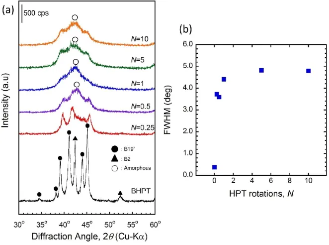
Fig. 2.2 (a) shows a series of XRD pattern of Ti-50mol%Ni before (BHPT) and after HPT deformation. The XRD pattern of the BHPT sample shows the sample is composed of the austenitic B2 phase and the martensitic B19’ phase. However, after subjected to the deformation by HPT at N = 0.25, significant peak broadening and a decrease in the peak intensity was observed. Further straining (N = 0.5) led to the appearance of halo centered at around 2 ~ 42º, which corresponds to the formation of amorphous phase. The XRD patterns appear almost unchanged by further straining. Fig. 2.2(b) shows the corresponding full width at half maximum (FWHM) of 2 = 42° (corresponding to austenite B2 (110) peak) of TiNi.
Fig. 2.2 (a) X-ray diffraction patterns of Ti-50mol%Ni before and after HPT deformation and (b) its corresponding FWHM at 2θ ~ 42º.
XRD patterns for Ti-50.9mol%Ni before and after HPT deformation is shown in Fig. 2.3(a). The XRD pattern of the BHPT sample shows the main peak at 2θ ~ 42º, corresponding to the (110) austenitic B2
26
phase. After HPT deformation of N =0.25, the peak intensity of (110) decreases and peak broadening was observed. Small peaks seen on the shoulder of the (110) peaks of B2 phase correspond to (002) reflection of B19' martensite phase, which may be due to stress-induced martensitic transformation during HPT deformation. At N =1, the intensity of (110) peaks with substantial broadening were observed to be slightly pronounced. Further straining at N =5 shows the (110) peak is more distinct in comparison to lower number of rotations. The corresponding N =5 sample’s FWHM of 42° shown in Fig. 2.3(b) slightly decreases. This observation may be attributed to the higher fraction of B2 nanograin. Further straining led to a halo centered at 2θ ~ 42º which corresponds to the formation of amorphous phase. This observation indicates the grain refinement and phase transformation due to the accumulation of dislocations during HPT deformation.
Fig. 2.3 (a) X-ray diffraction patterns of Ti-50.9mol%Ni before and after HPT deformation and (b) its corresponding FWHM at 2θ ~ 42º.
27 2.3.2 Mechanical properties
Micro-hardness measurements were done to confirm the change in the structure in the TiNi alloys due to HPT deformation. Fig. 2.4 shows the Vickers micro-hardness as the function of the distance from the disk center. For Ti-50mol%Ni alloys (Fig. 2.4(a)), the hardness of BHPT sample was found to be at 220 Hv. The average hardness of the samples increases two-folds after HPT-deformation of N = 0.25. At the low number of turns, the edges of the samples possess higher hardness compared to the center of the same disk. Strain hardening caused by HPT increase the hardness in the sample. This is a typical behavior of the materials subjected to HPT processing.
Fig. 2.4 Micro-hardness of (a) Ti-50mol%Ni and (b) Ti-50.9mol%Ni before and after deformation with different turns as a function of distance from the disk center.
2.4 Discussion
SPD methods are regarded as attractive processing technique due to its ability to achieve grain refinement in a fully dense, bulk material. In HPT technique, high degree of straining is imposed on the samples. Table 2.1 shows the determined degree of torsional deformation of each samples calculated at the edge of samples based on Eqn 1.2, Eqn 1.5 and Eqn 1.6 as discussed in Section 1.3.
Table 2.1 Degree of torsional deformation with different number of revolutions (edge of sample) Number of
rotation, N
True accumulated strain, e
Shear strain,γ Equivalent Von Mises strain, εequiv 0.25 2.22 9.24 5.33 0.5 2.92 18.48 10.67 1 3.61 36.96 21.34 5 5.22 184.80 106.69 10 5.91 369.60 213.39
28
The large strain imposed leads to the phase changes as observed in Fig. 2.2 and Fig. 2.3 for Ti-50mol%Ni and Ti-50.9mol%Ni, respectively. The only stark difference between this two alloys is the initial austenitic B2 phase of Ti-50.9 mol% Ni is more stable and less susceptible to amorphization. The tendency to form the amorphous structure under HPT conditions is at the strongest when the samples were in stable martensitic state [12]. This is due to relatively higher degree of imperfection on the crystal lattice if slightly Ni-rich Ti-50.9 mol% Ni [12].
The phase transformation observed from XRD pattern can be summarized as follows. When subjected to a low number of rotation (N = 0.25 and 0.5), decrease in B2 intensity and emergence of B19’ martensite peaks indicate the deformation-induced martensitic transformation. The original B2 austenite is transformed into self-accommodated martensite with various variants. With further deformation, the martensites are subjected to reorientation and turn into same orientation in a definite grain. When the deformation increases, the high density of dislocation lead to formation of dislocation cell in the grain, forming a nanocrystalline grains. Peak broadening on XRD suggests the mixed subgrain formation of B2 and B19’ [13]. Decreasing grain size with further deformation stabilized the B2 austenite and suppressed the martensitic deformation [14]. This translated into a slightly increased in peak intensity and reduced FWHM value at 2θ ~ 42º of N = 5 sample of Ti-50.9mol%Ni indicating increased in amount of B2 nanocrystal. With further deformation, the B19’ martensite transforms into the fragmented grain [13]. Further rotation at N = 10 finally produced amorphous structure with embedded nano-scale debris of B2 phase. After subjected to large plastic strain, high density of defects were induced and destroy the periodicity of the atomic arrangement, thus leads to the formation of amorphous phase amongst the retained nanocrystalline grains[15].
This results agrees with previous TEM observations of HPT-deformed TiNi [3,7,8,16]. It should be emphasized that the amorphization is very heterogeneous process [6]. Preferential sites for amorphization may be dislocation tangles, martensite twin boundaries and grain boundaries. Amorphization in the form of shear bands was also observed as shown in Fig. 2.5 [17].
29
Fig. 2.5 Schematic illustration of the nanostructures of HPT deformed TiNi as observed by TEM showing the nanograins (black) and amorphous (gray)region [17].
One of the drawbacks in HPT is that the variation of the imposed strain across the radial distance as shown in the hardness profile in Fig. 2.4. Inspection of Eqn. 1.12 suggests that processing by HPT will introduced a very significant inhomogeneity into the material, so that both the microstructure will be extremely inhomogeneous. However, this study demonstrated a gradual evolution towards a homogeneous structure in the HPT deformed samples with this evolution occurring by increasing the total number of rotations. In both TiNi alloys, at low rotation, lower hardness is observed in the central region of the disk. However, the hardness values in the centers gradually increase with increasing N. As the rotational number increases, the hardness becomes more homogeneous across the disks due to excessive strain accumulation introduced by extra rotation [3]. The hardness difference between the center and the edge tends to become relatively small as the number of rotation increases resulting in the overall increase in the micro hardness level. This result confirms the development of a gradual evolution in hardness across the disk diameters with increasing torsional straining.
2.5 Conclusion
In this chapter, we have demonstrated the gradual changes in structural and mechanical properties of TiNi alloys after subjected to HPT at various number of rotations. The study on the X-ray diffraction and microhardness of TiNi alloys after subjected to HPT deformation systematically confirms the change in the microstructure and mechanical properties. XRD patterns examination revealed that phase transformation from martensite to austenitic occurs in both TiNi alloys, with martensite suppression due to grain refinement. Microhardness characterization shows an evolution towards hardness homogeneity with increasing numbers of turns in HPT processing.
30
2.6 References
[1] Yamada K, Koch CC. The influence of mill energy and temperature on the structure of the TiNi intermetallic after mechanical attrition. J. Mater. Res. 1993;8:1317–26.
[2] Koike J, Parkin D, Nastasi M. Crystal-to-amorphous transformation of NiTi induced by cold rolling. J. Mater. Res. 1990;5:1414–8.
[3] Tsuchiya K, Inuzuka M, Tomus D, Hosokawa A, Nakayama H, Morii K, Todaka Y, Umemoto M. Martensitic transformation in nanostructured TiNi shape memory alloy formed via severe plastic deformation. Mater. Sci. Eng. A 2006;438-440:643–8.
[4] Green S, Grant D, Wood J. XPS characterisation of surface modified Ni-Ti shape memory alloy. Mater. Sci. Eng. A 1997;224:21–6.
[5] Tsuchiya K, Hada Y, Koyano T, Nakajima K, Ohnuma M, Koike T, Todaka Y, Umemoto M. Production of TiNi amorphous/nanocrystalline wires with high strength and elastic modulus by severe cold drawing. Scripta Mater. 2009;60:749–52.
[6] Sergueeva AV, Song C, Valiev RZ, Mukherjee AK. Structure and properties of amorphous and nanocrystalline NiTi prepared by severe plastic deformation and annealing. Mater. Sci. Eng. A 2003;339:159–65.
[7] Tsuchiya K, Cao QF, Hosokawa A, Katahira M, Todaka Y, Umemoto M. Nanostructured Shape Memory Alloys for Biomedical Applications. Mater. Sci. Forum 2007;539-543:505–10.
[8] Peterlechner M, Waitz T, Karnthaler HP. Nanocrystallization of NiTi shape memory alloys made amorphous by high-pressure torsion. Scripta Mater. 2008;59:566–9.
[9] Mahesh KK, Braz Fernandes FM, Gurau G. Phase Transformation in Ni-Ti Shape Memory and Superelastic Alloys Subjected to High Pressure Torsion. Amr 2010;123-125:1007–10.
[10] Valiev RZ, Estrin Y, Horita Z, Langdon TG, Zechetbauer MJ, Zhu YT. Producing bulk ultrafine-grained materials by severe plastic deformation. Jom 2006;58:33–9.
[11] Zhilyaev AP, Langdon TG. Using high-pressure torsion for metal processing: Fundamentals and applications. Prog. Mater. Sci. 2008;53:893–979.
[12] Prokoshkin SD, Khmelevskaya IY, Dobatkin SV, Trubitsyna IB, Tatyanin EV, Stolyarov VV, Prokofiev EA. Alloy composition, deformation temperature, pressure and post-deformation annealing effects in severely deformed Ti–Ni based shape memory alloys. Acta Mater. 2005;53:2703–14.
[13] Pushin VG, Valiev RZ, Valiev EZ, Kourov NI, Kuranova NN, Makarov VV, Pushin AV, Uksusnikov AN. Phase and structural transformations in the Ti49.5Ni50.5 alloy with a shape-memory effect during torsion under high pressure. Phys. Metals Metallogr. 2012;113:256–70. [14] Waitz T, Kazykhanov V, Karnthaler HP. Martensitic phase transformations in nanocrystalline
NiTi studied by TEM. Acta Mater. 2004;52:137–47.
[15] Zhang Y, Jiang S, Hu L, Liang Y. Deformation mechanism of NiTi shape memory alloy subjected to severe plastic deformation at low temperature. Mater. Sci. Eng. A 2012. [16] Tsuchiya K, Ohnuma M, Nakajima K, Koike T, Hada Y, Todaka Y, Umemoto M.
Microstructures and Enhanced Properties of SPD-processed TiNi Shape Memory Alloy. Mater. Res. Soc. Symp. Proc. 2009;1129.
[17] Peterlechner M, Waitz T, Karnthaler HP. Nanoscale amorphization of severely deformed NiTi shape memory alloys. Scripta Mater. 2009;60:1137–40.
![Fig. 1.5 Schematic representation of the process of protein adsorption on a solid surface [14]](https://thumb-ap.123doks.com/thumbv2/123deta/8499566.923025/21.918.219.731.102.456/fig-schematic-representation-process-protein-adsorption-solid-surface.webp)