2007年 3 月
Japan Aerospace Exploration Agency
JAXA Special Publication
ISSN 1349-113X JAXA-SP-06-016
宇宙航空研究開発機構特別資料
宇宙航空研究開発機構
2006年度宇宙関連プラズマ研究会講演集
宇宙科学研究本部
船木 一幸 編
はじめに ‥‥‥‥‥‥‥‥‥‥‥‥‥‥‥‥‥‥‥‥‥‥‥‥‥‥篠原俊二郎・谷川 隆夫・佐々木 進
阿部 琢美・船木 一幸 ‥‥‥‥1
静電プローブ測定−特にマッハプローブについて−
‥‥‥‥‥‥‥‥‥‥‥‥‥‥‥‥‥‥‥‥‥‥‥‥‥‥‥‥‥‥‥‥‥‥‥‥雨宮 宏 ‥‥‥‥3
Flight-type-probe for Measuring the High Density and High Temperature Plasmas
‥‥‥‥‥‥‥‥‥‥‥‥‥‥‥‥‥‥‥‥‥‥‥‥‥ K. Uehara, Y. Sadamoto, H. Amemiya
K. Oyama, Y. Nagashima ‥‥‥11
フロー速度シア及び負イオンによるドリフト波の変調
‥‥‥‥‥‥‥‥‥‥‥‥‥‥‥‥‥‥‥‥‥‥‥‥市来 龍大・林 賢一郎・金子 俊郎
畠山 力三 ‥‥‥22
宇宙研における大容量−高密度ヘリコンプラズマ実験
‥‥‥‥‥‥‥‥‥‥‥‥‥‥‥‥‥‥‥‥‥‥‥‥谷川 隆夫・篠原俊二郎・船木 一幸
山際啓一郎 ‥‥‥30
大強度短パルスマイクロ波ビームの発生と応用に向けた研究
‥‥‥‥‥‥‥‥‥‥‥‥‥‥‥‥‥‥‥‥‥‥‥‥‥‥‥‥‥‥栗原 智章・安藤 利得 ‥‥‥35
Possible Earthquake Effect on Electron Temperature in the Afternoon Overshoot at 600km - Contribution of Space Plasma Chamber to the Accurate Measurement of Te -
‥‥‥‥‥‥‥‥‥‥‥‥‥‥‥‥‥‥‥‥‥‥‥‥K.-I. Oyama, Y. Kakinami, H. Kamogawa
T. Kodama, J.Y. Liu ‥‥‥44
イオン風中の帯電微粒子近傍におけるイオンの軌道計算
‥‥‥‥‥‥‥‥‥‥‥‥‥‥‥‥‥‥‥‥‥‥‥‥眞銅 雅子・中村 良治・石原 修 ‥‥‥50
マグセールワーキンググループについて
‥‥‥‥‥‥‥‥‥‥‥‥‥‥‥‥‥‥‥‥‥‥‥‥‥‥‥‥‥‥船木 一幸・山川 宏 ‥‥‥56
小ヘリコン源を用いたプラズマ生成・加速
‥‥‥‥‥‥‥‥‥‥‥‥‥‥‥‥‥‥‥‥‥‥‥‥都木恭一郎・橋本 隆・牧田 賢治 田中 良和・篠原俊二郎・羽田 亨 池田 泰・谷川 隆夫・船木 一幸
K.P.Shamrai ‥‥‥62
電気推進の研究・開発・宇宙利用の方向性について
‥‥‥‥‥‥‥‥‥‥‥‥‥‥‥‥‥‥‥‥‥‥‥‥‥‥‥‥‥‥‥‥‥‥‥‥國中 均 ‥‥‥67
Characteristics of a Magnetized Inductively Coupled Plasma in the Presence of a Double Layer
‥‥‥‥‥‥‥‥‥‥‥‥‥‥‥‥‥‥‥‥‥‥‥‥‥‥‥‥‥‥‥‥‥S.Popescu, H. Fujita ‥‥‥75
「宇宙関連プラズマ研究会 2006」は宇宙航空研究開発機構(JAXA)宇宙科学研究本部(ISAS) (相模原市)で 2006 年 12 月 19 日と 20 日に行いましたが、この研究会は 2003 年 12 月 16 日に始めまして 4 回目となります。2 回目は 2004 年 12 月 17 日、3 回目は 2005 年 12 月 14 日でした。元々は 2000 年頃から宇宙科学研究本部でのスペースプラズ マ共同研究に関連して、有志で始めましたインフォーマルな勉強会が母体で、時間を気にせず徹底的に幅広く色々な 議論を致しました。本研究会ではこれで閉じず更に発展させて宇宙/スペース関連のプラズマの多彩さ、面白さを勉 強するため、また宇宙科学研究本部で毎年度末にありますフォーマルな「スペース・プラズマ研究会」と相補的にも なるよう以下のような趣旨で始めました。理学、工学や実験/観測、理論、シミュレーションに限らず、宇宙のプラ ズマに関連する様々なトピックスを自由に議論して視野を広げ、異なる研究分野や研究者と相互交流し今後の皆様の 新研究や共同研究の展開に資するところがあればとの趣旨です。お蔭様で研究会を進める毎に、講演数、参加者共に 増えている事は喜ばしい事です。なおこの研究会の発展には、宇宙科学研究本部をご退職なされました中村良治先生、
小山孝一郎先生にも色々とお世話になっております。
今回は参加者と講演者の増加に伴い、従来一日であったのが初めて二日間となり、内容としては特別講演と三部制 としました。特別講演では、静岡大の山際先生に長年に亘る興味深いビームプラズマの非線形現象、静電プローブの 第一人者である中央大学の雨宮先生には、前以って参加者から戴いたプローブ測定の質問に対するご回答も含めご講 演を戴きました。第一部は地上実験で、先端プローブ測定、ドリフト波不安定性、高周波プラズマの特性、大強度マ イクロ波ビームについて、第二部はスペース及び理論で、太陽電池セルの損傷、電離圏と地震、ダストでのイオン風、
パルスと粒子の相互作用、高次統計解析と、多彩な内容で種々の質疑応答がなされました。翌日の第三部はプラズマ 推進に絞り、MPD での高周波加熱、マグセール、大電力ミリ波プラズマ、小へリコン源、電気推進の方向性について 活発な議論があり、最後には今後の展望について自由討論がなされました。本講演集では、こうしたご講演の一部を 論文形式で掲載しています。
言うまでもなく宇宙/スペースプラズマ研究では観測、基礎実験、理論/シミュレーションの有機的結合が緊要で あり、また一方、基礎と開発研究は、応用・展開研究を行うための重要な両輪であり、分野横断的な多角的議論、研 究が一層求められていると考えております。今後共研究会を上記の趣旨で進めたいと思っておりますが、より良い発 展のため、本研究会への憚りないご意見とご支援を戴ければ幸いです。
研究会世話人 九大 総理工 篠原俊二郎 東海大 総科研 谷川 隆夫
JAXA / ISAS 佐々木 進
阿部 琢美
船木 一幸
1. はじめに
わが国での流れのあるプラズマ中のプローブに関するおそらく最初の研究はロケット搭載プローブの設計がなされ た時であろう [1] .メッシュ状の球型プローブが表面からの光電子を避け,流れを考える上で最適な型とされ,相対速 度効果の補正,Single Probe としの動作条件ついて考察され予備実験の結果最初の電離層観測が 1960 代に行われた
[2] , [3] .電子密度と電子温度は自らが開発されたレゾナンスプローブから,正イオン密度は球プローブのイオン飽和
電流 I
+から得られた.I
+のマッハ数(ここでの記号η
o1/2)に対する関係は球の前後のシースに縮みと膨らみを仮定し て解析された [4] .Fig. 1 にその結果を示す.
ここで,I
+=4π R
p2j
o+φ( η
o), η
o=M
+u
2/2κ T
+, j
o+=n
+e<v
+>/4.点線は球を正射影である円板と仮定して得た Boyd の結果 である.
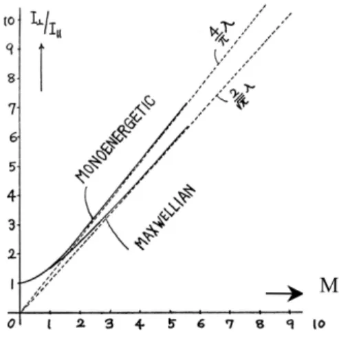
一方,実験室でマッハ数を測るという立場からは円筒プローブを用い流れに対し軸を水平(I
‖),垂直にした場合
(I
⊥)の電流比を測定する方法を考え,上記方法を円筒に適用してマッハ数 M と電流比の関係を得た [5] .電流比 I
⊥/I
‖はデバイ数 D
λ(=R
p/ λ
D) とプローブ電圧の関数で,Fig. 2 にプローブ電圧および D
λが非常に大きい場合を示す.
*Chuo University
Fig. 1. 球プローブの流速による影響
雨 宮 宏
*An Overview of Electrostatic Probe Measurement
By
Hiroshi A MEMIYA
*Abstract: Previous work on the Mach probe in Japan and some examples of the probe used in a wind tunnel,
supersonic mercury jet, a plasma gun, ionospheric plasma on board rockets and tokamak boundary plasma
are briefly described. Physical and technical problems raised by users are also discussed.
4
2. 低密度風洞でのプローブ実験
以上では自由分子流を仮定していたので超音速の場合にも適用されたが,実際にはクヌーセン数 K
e,i(= λ
e,i/R
p) が大 きくないと連続媒質効果が効いて来る.そこで,低密度風洞(宇宙研駒場)を用いて種々の圧力で超音速流プラズマ 中での球の周りのイオン,電子密度分布,圧力分布を夫々プローブおよびピトー管を用いて測定した.8 mmφの球の 周りを 0.2 mm φ, 2 mm 長の円筒プローブで測定した.マッハ数 M の大きい程前方の密度は大きいのに対し後方の密度 がウエークの影響が効いて小さくなっている.圧力は球の前方で衝撃波の影響があるのか大きくなり下流では下がっ ている [6](Fig. 3) .
球の前のバーは理論上の衝撃波の位置,点線はシースを示す.実験条件 p=0.03Torr では衝撃波による不連続は見ら れないが密度の凹凸が見られる.D,E 層のロケット搭載プローブでは衝撃波を考慮する必要がない様に見える.しか し,流れにより球の周りの荷電粒子密度,圧力分布は明らかに非対称になっていて,その前後で D
λおよび K
e,iが違う という複雑な状況を考慮しなければならない事を意味する.
3. 水銀ジェットを用いたプローブ実験
実験室で超音速プラズマを得るアイディアとして拡散ポンプ型 [7] を適用し Hg-Jet(Fig. 4)と RF 放電により球およ び楔の周りの発光状態から衝撃波の存在を調べた(Sci. Paper Inst.Phys.Chem.Res. 64(1970)99) .Hg の圧力は蒸気圧 と温度の関係から求めた [8] .Fig. 5 に球の前面の発光,楔の周りの発光状態を示す.マッハ数 M と Stand-off 間隔の 関係(球) ,M と角度の関係(楔)[9] からマッハ数を決定した結果,ほぼノズルの設計値と一致した.
Fig. 3. 球の周りの密度,圧力分布
Fig. 2. 円筒プローブの電流比
I⊥/I
‖4. プラズマガンにおけるプローブ測定
流体プラズマとしてプラズマガン [10] を用い自由分子流論(collisionless)と連続媒質論(collisional)のいずれが良 く合うかを調べた(東大宇宙航空研報告 7(1971)210) .流れに面を垂直に置いた円板プローブと軸を平行にした円 筒プローブからなるダブルプローブを用いその電流比からマッハ数 M=u/<v
+> を推定した.前者には衝撃波がシース の前面に出来る Stagnation probe [11] を仮定した.電子とイオンの温度は熱平衡にあるとし電子温度はプローブ特性か ら , 流 速 は 上 流 と 下 流 に 置 い た 二 つ の プ ロ ー ブ 電 流 の 時 間 差 か ら 求 め た . 例 と し て , ガ ン 電 圧 V
G=1 6 k V で
T
e~T
i=1.8eV; u=6.5 × 10
6cm/s, M=3.5 を得た.自由分子流論によると平板プローブの電流密度 j は,イオンの速度分布
を流速 u の Drift-Maxwell 分布と仮定すると u=0 の場合の電流密度 j
oに対し次式となる.
(1)
連続媒質理論では超音速では平板の前面に衝撃波が生ずるのでその前後の圧力比 p
21,密度比 n
21,温度比 T
21は上流 の M
1の関数となり,平板プローブの電流密度は次式となる.
(2)
(3)
Fig. 4. 水銀ジェット
球 楔
Fig. 5. 衝撃波の写真
6
ここで,衝撃波に対する Rankine-Hugoniot の関係式 [9] を使い,γは比熱比を表す.円筒プローブは K
i,e>>1 なの で自由分子流論が成り立つとする.両理論から計算した電流比とマッハ数の関係を Fig. 6 に示す.図から実験値は連 続媒質論により良く一致することが分かる.
5. ロケット搭載プローブ
ロケット搭載プローブではイオン飽和領域は必然的に相対速度効果を考慮せねばならない.電子温度ないし電子エ ネルギー分布の従来の測定法はイオンシースのマッハ数と逆電位による歪みを受け,その補正を要する筈である.し かし,その様な補正の例は見当たらない.そこで,我々は電子温度の測定値は正負の飽和電流値との組み合わせで荷 電粒子密度の決定のみに限定した.ロケットの軌道は理論的には推力,抵抗,スピン,風を考慮したロケットの運動 方程式から決定される [12] .実際はロケット搭載のトランスポンダから得るロケット軌道,スピン,スターセンサの データを利用し,ロケット軸に対し面を平行にしたファラデーカップの面の流れに対する相対速度を決定し自由分子 流理論を用いて流れに対する修正を行った.等価イオン密度は世界の Ion Species の高度分布のデータから推定した.
これにより中緯度および極域で電子密度,正負イオン密度の高度分布が得られた [13] .しかし,流れのあるプラズマ 中での電子温度の精密測定法は今後の開発にかかっている.
6. 核融合周辺プラズマでのプローブ測定
周辺(エッジ)プラズマでの大きい問題はイオン温度 T
iが電子温度 T
eを如何に上回るかとプラズマの流れであった.
上原,津島,定本,前田氏らとの共同研究により原研の JFT-2M とドイツ Forschunszentrum/Jülich の TEXTOR で回転 ダブルプローブ [14] ,非対称ダブルプローブ [15] ,Toothbrush プローブ [16] ,流れに対向する円板プローブ[17] ,イ オン敏感プローブ [18] を用いて T
i,T
e,u を測定した.その結果,コア条件により T
i=4-10T
e; M=u ・ cos θ/<v
i> =0.2-0.4 を得た.ここで,M= u/<v
i>;<v
i>=[κ(T
i+T
e)/M
+]
1/2と定義した.一般に音速は各条件で異なり,電子とイオンの比熱比 およびイオンの荷電数を考慮したイオンマッハ数,磁場特有のアルフヴェンマッハ数,磁気音波マッハ数が定義され ている [19] .
Fig. 6. マッハ数とプローブ電流比の関係
7. コメント
講演に先立ちマッハプローブに関し各種問題が提起された(下記イタリック部分) .これらは今後詳細な研究を要す る問題で,自分なりのコメントを付記するに留める.
(1)マッハ・プローブでマッハ数を見積もる場合,採用すべき物理モデルの選択基準は?
例:超音速プラズマ流,衝突プラズマ,無衝突プラズマなど
理論的取り扱いとしては自由分子流(collisionless),連続媒質論(collisional)がありクヌーセン数 K
i,e>>1,
K
i,e<<1 により区分される(添字 i,e はイオン,電子) .プラズマでは他にデバイ数 D
λ(プローブ寸法/デバイ長)が 問題になる.D
λ>>1 ではシースが非常に薄くなり流れによるシースの歪をあまり考慮しなくてもよくなる.Fig. 7 で 白い領域は衝突,無衝突プローブ理論が適用出来る領域を表す [20] .
・プローブ形状,サイズなどの選択法は?
Collisionless Model を採用する場合,シース半径 r
s,プローブ半径 r
pとする時,r
s-r
p<< λ(mfp) が必要となる.この 条件が充たされるかは K
i,eと D
λで左右される.
シース内の衝突回数 X
i,eが問題になる遷移領域では,プローブのイオン電流,電子電流に対して衝突効果の補正を 適用する必要がある [21] , [22] .
・測定精度,有効桁数は? 測定の信頼性をどう考えたらよいか?
Fig. 7 の白い領域が衝突,無衝突領域である.前者では拡散係数,移動度を使った理論,後者では Langmuir 以来軌 道運動理論を使った理論が周知である.斜線の遷移領域ではシース内の衝突効果 [21] , [22] を正しく入れないと誤差が 大きくなる.測定結果のモデルへの適合性,信頼性は K
i,e>>1,K
i,e<<1,D
λ>>1 の充たされ方によると考えられる.
・適用可能なマッハ数領域は?
一次元 Fluid Model では強磁場中の平板プローブの上流,下流面の電流比とマッハ数の関係が亜音速で得られている
(M < 1)[23] .超音速では衝撃波の影響を取り入れねばならず,シース厚<衝撃波面位置(stand-off distance)のもと で Stagnation Probe が考えられた [11] .一方,K
i,e>>1 では Kinetic Model がマッハ数全域に適用されている [24] .
・電極側面による荷電粒子捕捉の影響は?・背向する2枚の電極間隔の決め方は?
磁場のある場合は側面への電流は磁力線に沿って色々なジャイロ半径で飛んでくる荷電粒子を考慮して計算される.
例えば無衝突モデルで磁場と流速に軸が平行な円筒プローブでは,磁場強度に応じた側面への電流が計算出来,端面 への電流は Drift Maxwellian の仮定のもとで計算されている [15] .従って,側面+上流側面,側面+下流側面からなる 2枚の電極の電流比からマッハ数が得られる可能性がある.
(2)プローブが存在すること自体のプラズマへの影響をどう評価すべきか?
プローブによる擾乱を回避するには,プローブ電流 i
p<<放電電流 i
dまたは i
p<< i
+*S
w(S
w: 基準電極)であること が要求される.また,基準電極の面積>>プローブ面積,という条件も正しいプローブ特性を得る上で必要となる.
Fig. 7. プローブの適用範囲
20)8
特に磁場がある場合
強磁場中ではプローブ飽和電流が理想値から抑えられる他,プローブが磁束管(Flux tube)を形成するためアスペ クト比が問題となり単に基準電極の面積を大きくすることは意味がなくなり,無衝突条件で極端に強磁場の場合プロ ーブ飽和電流は極端に小さくなる [25] .
(3)結果のクロスチェックの仕方にはどのようなものがあるか?例:計算機モデルの結果との比較など
プローブの上流面の電流と下流面ないし側面の電流比から直接マッハ数が得られる場合があるが,一方速度 u と T
i, T
eとを独立に測定することによりマッハ数を得る方法もある.
上流面と下流面の電流比 R
iとマッハ数 M の関係は,経験的に R
i=exp (k*M) と表されモデルにより k=0.8, 1.2, 1.7, 1.75, 2.7 の様に変化する [24] .この際,音速の定義も重要で磁場強度やγによって変わる [19] .イオン温度が高い場 合 T
i/ T
eによる変化が大きい[17] , [24] .
(4)粘性,拡散のプローブ捕集への効果をどう評価すべきか?
連続媒質論では拡散係数 D,粘性ηを考慮する必要がある
23).磁場のある場合無衝突でも D,ηはテンソルとなり 磁場に対する方向を考慮する必要がある.
(5)マッハ・プローブを通常のラングミュア・プローブとして使用する際に特に注意すべき事項はあるか?
マッハ・プローブでもプローブ測定の次の留意点は考慮されねばならないだろう.
1)プローブ寸法: K
i,e,D
λを考慮して理論への適用性を決める.
2)基準電極の面積:正常に電子飽和電流が得られるだけの大きさが必要.
3)高周波プラズマ,プラズマノイズ:(7)項に後述.
4)プローブの表面の汚染:加熱,スパッタ法による清浄化.Quick injection 法を適用.
5)プローブ表面の光電子,二次電子,反射:ビームの測定では特に注意が必要となる.
(6) 25 mm 内径のガラス管内での流速測定について.最適の方法は何か?現在,磁場に対して垂直面,平行面を持つ プローブを使用しているが,両面の距離が約 3 mm あり,流速が小さいと思われる場合でもイオン飽和電流値に大き なアンバランスがあり測定精度に自信が持てない.対策:高周波プラズマのプローブ測定としてはプローブの更なる 小型化ということになるのか?
磁場に対し垂直,水平な面の平板プローブの電流 i
⊥, i
‖は連続媒質論では共に圧力効果,磁場強度により減少しその 度合いは i
‖の方が大きい(但し,円板)[26] .無衝突では i
⊥は磁場の影響を受けないが,i
‖は磁場強度と共に減少す る(但し,矩形板)[27] .
流れがある場合の上記の Fluid model [23] および kinetic model [24] では磁場と流れが平行であることが仮定されたが,
必ずしも磁場//流速は当てはまらない.そこで,磁場に対しては連続媒質モデル,流れに対しては自由分子流モデルを 用いて回転平板プローブによるマッハ数の決定法を開発した [28] .理論的予測はトリプルプローブで測定されたトカ
マク JFT-2M 内の流れのパターン [29] と対応する結果を示している.
(7)マッハ・プローブに拘らず,高周波(rf, マイクロ波)プラズマ中でのプローブについて.通常のプローブ法は適 用可能なのか?
電子温度測定は何故難しいのか?
磁場中では球,円筒プローブのシースの形は楕円形に歪み,流れがあると球,円筒の前後で荷電および中性粒子密 度が変わるのでさらに非対称に歪むだろう.磁場と流れが互いに角度をなすと,シースの歪みは一層複雑となるだろ う.速度分布や電子温度はイオンシースが形成されている逆電位領域で測定されるが,球,円筒プローブでは磁場や 流れ,プローブ電圧によってシースの形が変形するので電流の半対数プロットの傾斜が直線に載るとは考えられない.
このため,初期にロケット搭載プローブで考えられた球プローブの使用や電子温度測定法自体には疑問が残る.平板 プローブで D
λ>>1 が充たされる場合には,シースは薄くなるため端効果を除いては取り扱いがより簡単になると思 われる.我々が平板状ファラデーカップを用いた理由はここにある.
計測に際して注意すべき点は何か?
プラズマ装置におけるパラメータ変動(ドリフト)は,a. ガス流量,圧力の変動, b. 入力パワーの変動,c. 管壁温
度,ガス温度の上昇,d. 不純物の影響,e. 複雑な境界条件,等で起こるとされている.プラズマの揺らぎのプローブ
への影響をまとめると,
#1.プラズマ電位に振幅 V ~
の正弦波揺らぎがある場合,電子電流に対する歪みはエネルギー分布がマクスウエル分布 の場合,電子電流反発領域の時間平均電流は
(4)
となるので(I
o(x): 第1種変形ベッセル関数) ,半対数プロットの傾斜から T
eが得られる.しかし,エネルギー分布 f (E) が非マクスウエル分布の場合は複雑な整流効果歪が生じる.
#2.プラズマ密度揺らぎは加算平均処理で消去される.
#3.T
e, f (E) の変動は位相,時間分解計測が必要になるが,サンプリング歪に注意を要する.
高周波プラズマでのプローブ歪み除去法としては次の方法がある.
1.大容量による短絡:プローブの周りに導体輪やブロックを配置しシース容量を短絡.
2.フィードバック法: RF 電源からの電圧をプローブに負帰還させ RF 電位を補償する.
3.参照プローブによる RF 電圧補償:別のプローブで RF 電圧を受信しプローブ電圧を補償.
4.並列共振回路挿入:高いインピダンスの回路により高周波電圧を遮断する.
5.データサンプリング: RF 周波数に同期した一定位相での時間分解測定.
6.微小交流重畳法で f (E) を測定: RF 周波数に無関係の周波数の微小交流を重畳する.
8. 結論
流れや磁場のあるプラズマ中のプローブ測定については,最近の解説 [30] が役立つことを期待する.今後,一般に 流れと磁場とが任意角度をなしたプラズマ中で,粘性,衝撃波,ウエーク,渦などの影響を考慮したプローブ理論や 計測技術の発展を希望する.
参 考 文 献
[1] T.Ichimiya, K.Takayama and Y.Aono, Rep.Ionos. & Space Res. 13(1959)155.
[2] 一宮、土手、高山、日本物理学会誌 17(1962)384.
[3] 一宮、土手、応用物理 35(1966)293.
[4] T.Dote, K.Takayama, T.Ichimiya, J.Phys.Soc.Japan 17(1962)174.
[5] H. Amemiya and T. Dote, Japan.J.Appl. Phys. 5(1966)957.
[6] 土手、雨宮、一宮、蜂巣、玉木、物理学会予稿(北大)13A-I-5(1965 July).
[7] A.I.Carsewell, Rev.Sci.Instrum. 35(1964)1557.
[8] R.W.Ditchburn & J.C.Gilmor, Rev.Mod. Phys. 13(1941)310.
[9] H.W.Liepmann & A.Roshko, Elements of Gasdynamics, 1960.
[10] 久保、矢守、伊藤、河島、東大宇宙研報告 6(1970)232.
[11] L.Talbot, Phys.Fluids 3(1960)289.
[12] 玉木章夫、飛しょう体の空気力学、東大出版会、1970.
[13] H.Amemiya & Y.Nakamura, J.Geomag. Geoelect. 45(1993)219, 48(1996)391.
[14] K.Höthker et al. Rev.Sci.Instrum. 61(1990)114.
[15] H.Amemiya & K.Uehara, Rev.Sci. Instrum. 65(1994)2607.
[16] K,Uehara et al., Japan.J.Appl. Phys. 36(1997)2351.
[17] M.Maeda et al., Japan. J.Appl.Phys. 36(1997)6992; 38(1999)2971.
[18] K.Uehara et al. J.Phys.Soc.Japan 66(1997)921; 72(2003)2804.
10
[19] 安藤、プラズマ核融合学会誌(J.Plasma Fusion Res.)81(2005)524.
[20] M.Tichy et al., Proc. 23. Int.Conf.Phenom.Ioniz.Gases(1997)C4-397.
[21] S.A.Self and C.H.Shih, Phys.Fluids 11(1968)1532.
[22] R.R.Aslanbekov, et al., Plasma Source Sci.Technol. 3(1994)528.
[23] I.H.Hutchinson, Phys.Fluids 30(1987)3777.
[24] K-S.Chung and I.H.Hutchinson, Phys.Rev. A38(1988)4721.
[25] A.Tsushima et al., in Double layers, World Scientific,(1997)254.
[26] T.Dote, H.Amemiya & T.Ichimiya, Jap.J.Appl.Phys. 3(1964)789.
[27] H.Amemiya and K.Uehara, Japan.J.Appl.Phys. 45(2006)247.
[28] H.Amemiya, A.Tsushima & G. Fuchs, Contrib.Plasma Phys. 39(1999)515.
[29] B.M.Annartone et al., Nucl.Fusion 34(1994)1453.
[30] 雨宮、和田、豊田、中村、安藤、上原、小山、酒井、橘,「プローブ計測の基礎から応用まで」プラズマ核融合
学会誌(J.Plasma Fusion Res.)81(2005)482-521.
I. INTRODUCTION
An electrostatic probe is a simple and convenient diagnostic tool for measuring the plasma density and temperature with high spatial and time resolutions. In low temperature plasmas, many kinds of electrostatic probes are widely used for measuring the plasma to clarify the mechanism thereof. In the hot and dense fusion plasma, however, the application of the electrostatic probe is limited to such a localized region as the scrape off layer (SOL), since the conventional probe would be destroyed in the core plasma region due to the great heat damage and/or the electromagnetic force during the plasma disruption. For the measurement of plasma parameters of high density and high temperature plasmas nowadays, indirect methods using electromagnetic waves, charged particle beams and spectroscopic methods are available. However, the spatial resolutions of these active and passive diagnostic methods are not good since it is so difficult to identify the original location generating signals. Furthermore, since these signals may often contain complex physical quantities related to passive and active lights it is difficult to analyze and to identify the precise plasma parameters.
In order to make the best use of the electrostatic probe having a high spatial and time resolution, we consider a flight-type- probe (FTP), in which the probe circuit and memory elements are installed in a capsule to be thrown into the core hot plasma from one side port with a fast speed. This is intended to prevent the probe from melting due to the hot plasma. The measurement is completed during the flight of the FTP and the data acquired are transmitted to observers outside observers by rf signals and/or are saved in the memory elements of the FTP to be analyzed after reproduction [1].
As early as the 1970s the current profile, which is an indispensable quantity in tokamaks, could not be measured in large tokamaks. In such a small tokamak as MINIMUK with the relatively low temperature and weak density plasma, however, the current profile in the core plasma has been successfully measured with a high spatial and time resolution by the magnetic probe
* Japan Atomic Energy Agency
** Joetsu University of Education
*** Graduate School of Chuo University
**** Tokyo Metropolitan University
***** Kyushu University
Temperature Plasmas
K. U EHARA
*, Y. S ADAMOTO
**, H. A MEMIYA
***, K. O YAMA
****, Y. N AGASHIMA
*****Abstract: The flight-type-probe (FTP) for measuring the high density and high temperature plasmas is proposed. The FTP is designed as a compact magnetic and/or an electrostatic probe, which travels with a fast speed through the core plasma, in order to measure the core plasma parameters simultaneously. The obtained information signals are transmitted by the rf signal from the core plasma side towards the observer during the flight and/or stored in the compact CPU elements buried in the FTP for the analysis after the flight.
Key words: flight-type-probe (FTP), magnetic probe, electrostatic probe, fast speed, measuring core plasma,
rf signal, compact CPU
12
whereby the mechanism of MHD instability has been precisely clarified [2]. Later, the current profile in the large tokamak could be measured by the spectroscopic method using the fast beam probe with the principle of Zeeman effect [3] and with the motional Stark effect [4] and with the soft X ray emission [5]. However, the instrumentation of these diagnostics is large and the performance is complicated.
If not only the magnetic probe but also the electrostatic probe can be inserted into the hot plasma, the capability of the diagnostic tool must be enhanced to clarify various plasma parameters with a higher spatial and time resolution. Development of the computer memories and the CPU capability has become remarkable recently. For example, the areas of the CPU and the memory have become as small as a pin like elements, which has made it possible to manufacture moble telephones. The development of memory content has greatly progressed in the last fifteen years. In 1990 only the 128 kB memory could be stored on 8 inch (19.6 × 19.6 cm) floppy disks, however, nowadays the 512 MB memory can be stored at the size of 1.5 × 1.0 cm chips in mobile phones. The performance of the FTP is imagined as an ultra-miniature mobile telephone being thrown into the hot plasma. If the size of the probe including the data acquisition system is packed in such a small region, the probe technique can be used for the measurement of the core plasma. It should be noted that before damage of the probe, the operation of FTP should be finished quickly. This corresponds to technical extension from the Reciprocating Langmuir Probe (RLP) [6] and from the rocket- borne electrostatic probes in space plasma [7]. In space plasmas, the Langmuir probe with the probe circuit and the amplifier is on board the rocket and the information signals are received by observers on the ground [8], however, the weight and the data acquisition system are too large and complicated to be used as the FTP.
In this paper, the hardware of the FTP is shown and the possibility of measuring plasma parameters using it in the core plasma is discussed.
II. DESIGN OF FLIGHT-TYPE- PROBE
A. Performance of the FTP
The RLP cannot be used in the whole region of the core plasma since it would be so troublesome for the housing surrounding
the signal cables to be immersed in the core plasma. This would disturb the plasma and would suffer from much heat damage and
would melt the RLP substance itself. In the case of FTP, this fear is avoided since the FTP has no support structure. The
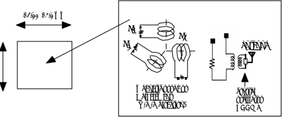
schematic performance of the FTP is shown in Fig. 1, where the FTP is injected with a fast speed from one side-port, crossing the
total region through the core plasma to reach another side-port with a shock absorber. The dimension of the FTP is made as small
as 1 cm and the probe pin for the electrode is about 1 mm in length. The probe circuit and the CPU system are installed in a so
reduced localized region that is buried in the insulating material like the boron nitride or the macor-H. Several types of the FTP
are prepared and the special launcher chamber room for the FTP is equipped, which is controlled in a high vacuum condition being
separated from the atmospheric room by the gate valve. When the FTP is used, both gate valves of A and B are opened and the
FTP is injected towards the core plasma. The process is remote controlled automatically. During the flight of the FTP signals
from the core plasma, which are mainly a voltage drop due to the probe current from the core plasma, are received by the FTP and
are stored in the CPU memory and/or are immediately transmitted by the rf signal. The probe circuit must be triggered by the
remote signal. After the flight, both gate valves are closed and the FTP is taken out for the analysis. Several kinds of
manufactured FTP’s manufactured are injected to observe the plasma parameters across the core plasma step by step using the
launching mechanism, which is either a pellet type injector [10] or a rail gun type [11]. It is necessary for the FTP not to rotate
against the magnetic field while measuring the ion temperature by the magnetic probe and by the differential double probe. The
rail gun has the merit of keeping a constant angle without any rotation after injection.
B. Structure of the FTP
Detail structures of the FTP are shown in Figs. 2 and Fig. 3. We consider two types of the FTP. One type is used to measure the current profile as shown in Fig. 2, which is denoted by MPRF-1. The other type is denoted by EPCPU-1 as shown in Fig. 3 and is used to measure the electron temperature Te, the ion temperature Ti and the floating potential V
f.
In the MPRF-1, the magnetic probe and/or Hall element for x, y and z direction measures the poloidal magnetic field B
θ(r), which gives the current profile J(r) in the core plasma of tokamaks. For the measurement of B
θ(r) we use the conventional magnetic probe technique with several turns coils and/or the Hall element. The voltage generated in the loop circuit of the magnetic probe and/or the Hall element is picked up through a finite resistance. The voltage signals of I
1, I
2and I
3are superimposed on the carrier wave of the crystal oscillator and are transmitted toward the observer outside the chamber, where we can acquire the data in real time. For the crystal oscillator, the voltage controlled is available due to the transmission of the signal, which is named as the voltage controlled crystal oscillator (VCXO). The candidate of this is, for example, ECCM7 of the Ecliptek corporation, the scale being 3.2 × 2.5 × 0.7 mm and the frequency of the carrier wave is 13.5 MHz. This element can operate at the atmospheric pressure below 85 ° C [12].
In the EPCPU-1, the triple probe and the differential double probe are installed with the probe circuit. The triple probe is used for measuring the electron temperature T
e(r) and the floating potential V
f(r), which are obtained by applying a constant bias voltage. For the measurement of V
fwe follow the procedure of JFT-2M, in which we observe the higher voltage across the detective resistance [13]. The differential double probe is used for measuring the ion temperature T
i(r). For the measurement of T
iwe follow the differential double probe (DDP) technique in which we can measure T
iby observing the ratio of the ion saturation current between two probe pins [14]. The real data of T
iusing the DDP has been successfully obtained in JFT-2M [15]. If we expect to measure the higher ion temperatures, a high voltage may be preliminarily charged in a condenser of the probe circuit before the flight since scale large batteries cannot installed in the FTP. The information signals are stored in a compact CPU elements, which includes the voltage exchanger circuit, A/D transformer with small batteries having about 5 volts and the memory elements. For detecting the initial state of measurement, an external trigger to the thyristor switch and/or the signal for leaving the contact must be received by an antenna from outside the chamber as shown in Fig. 3. In the measurement of the DDP it is necessary to use two insulating amplifiers to detect the voltage drop due to the fact that in the A/D transformer the voltage is measured against the common standard level. These elements have recently been highly integrated to a small region with a high
shock absorber
gate valve B
gate valve A
recover (memories installed case)
about 5.6 m core plasma
FTP
launcher room for FTP
receiving antenna (signalt ransmitted case)
Fig. 1
Schematic design of the performance of the flight type probe (FTP), where the scale of
plasma is assumed as that of ITER [9].
14
spatial resolutions [16]. For example, since the measuring points are 100 and a sampling time of 0.01 sec of the signal is necessary for the measurement of the spatial profile, then the necessary memories are estimated to be 1 kB per 1 channel. In the MPRF-1, 3 channels and 8 channel signals in the EPCPU-1, then the total memory may be lower than 10 kB, which could be fully installed in the reduced size FTP volume of about S= 2000 mm
3(12.6 × 12.6 × 12.6 mm) [17]~[18]. The proposed CPU is MSP430F149 of Texas Instruments, which is 9 mm × 9 mm size and can operate with a voltage of 1.83 ~ 3.6 V including the A/D and the CPU elements [19].
C. Method to draw out the data
How can we best draw out the data when the measurement of the FTP is performed ? Some kinds of advanced data acquisition are necessary in the FTP. In the case of the MPRF-1, since the data are transmitted during the flight and the measurement is made in real time, the some kinds of the receiving instruments including software to convert the real profile are necessary. The procedure is controlled by the acquisition system at the observer.
In the case of EPCU-1, since the data are analyzed after recovery, one of the possible methods of drawing out the data is
13.2〜14.2 mmI1
I2 I3
antenna
crystal oscillator ECCM7 magnetic probe or
Hall element (X, Y, Z direction)
Fig.2
The magnetic probe and the rf signal transmission (MPRF-1) of the FTP.
13.2〜14.2 mm
trigger trigger
triple probe differ ential double probe memory installed circuit
CPU installed memory element A/D
transform voltage
exchange circuit
Fig. 3
The electrostatic probe installed in the CPU memory (EPCPU-1) of the FTP which
contains the triple probe, the differential double probe and the CPU memory.
sending the data by the infrared rays inserting a small LD in the circuits, which is almost same as the remote control switch in a television.
D. Estimation of heat load
The FTP must travel through the core plasma quickly before being melted. We can estimate the temperature rise T of the FTP using the following equation of thermal conduction :
(1)
where ρ is the density , c is the specific heat, and λ is the thermal conductivity. We consider the FTP as a spherical object with radius r
0with a uniform temperature of 0 ° C. When the surface temperature of the object is suddenly brought to T
0, the time and space distribution of the temperature in the object is obtained as
(2)
from eq.(1), where s is integer. The temperature rise in the object is limited by the width of r
c=2π /[λ t/(c ρ )]
1/2, where the distance is estimated from the surface. We consider the temperature distribution of the object from eq. (2); then, the surface temperature of the FTP becomes
(3)
from the energy conservation law, where q is the heat power density flowing into the object and W=σ T
4is the black-body- radiation loss of the object, where σ is the Stefan-Boltzmann constant. The value of q is expressed as q = γ T
eJ
is, where T
eis the electron temperature, J
isis the ion saturation current density, and γ is the heat transmission rate which is given by
(4)
where, m
eis the electron mass, m
iis the ion mass, T
iis the ion temperature and δ
eis the secondary electron emission rate [20].
The value of W is expressed as W=σ T
4, where σ is Stefan-Boltzman constant as 5.672 × 10
-12Wcm
-2K
-4. The equation of (1) is solved by the numerical integral using the fifth order Lunge-Kutta method. We assume that J
isis presented by the ion saturation current J
is=0.61env
thi, where e is the electronic charge , n is the plasma density and v
thiis the ion thermal velocity. Furthermore, we assume the density and temperature profiles such as ; n=n
e0(1-(r/a)
2)
2, T
e=T
e0(1-(r/a)
2)
2and T
i=T
i0(1-(r/a)
2)
2, where a is the radius of plasma. We consider the ITER scale tokamak as the typical plasma parameter of the core plasma, such as n
e0=1 × 10
14cm
-3, T
e0= 10 keV, T
i0= 10 keV, a =200 cm, and the mass number A=2 (deuterium).
Equation (3) is numerically solved with the fifth-order Lunge-Kutta method. We denote the coordinates as follows: x is
major radius direction and y is the displacement from the equatorial plane. The FTP travels at the velocity v
0in the x direction,
apart from y from the equatorial plane; at which point t becomes (x+a)/v
0. When the FTP travels at the velocity of v
0below 10
km/s, which is the maximum velocity of flying objects shut by the rail gun, the estimated temperature of T
0is given in Figs. 5 (a)
and (b) for the tungsten electrode at y/a = - 0.7 and for the macor-H insulator at y/a = - 0.8. It is seen that the surface of the FTP
melts when the FTP travels near y = 0 and v
0is so small. However, the FTP would not melt at v
0= 8 km/sec and y/a = - 0.8 at the
final stage of the flight (x/a = 1), since the melting points of tungsten and macor-H is 3683 K and 2173 K, respectively. It would
be possible to measure the plasma parameters in this situation, since we consider the measurement with the FTP in the region of the
internal transport barrier [21]. For various y/a values corresponding to the barrier region, T
0as a function of x/a is shown in Figs. 6
(a) and (b). It is seen that the surface of the FTP would not be melted when the FTP travels at y/a < - 0.66 for tungsten and y/a < -
16
0.76 for macor-H with v
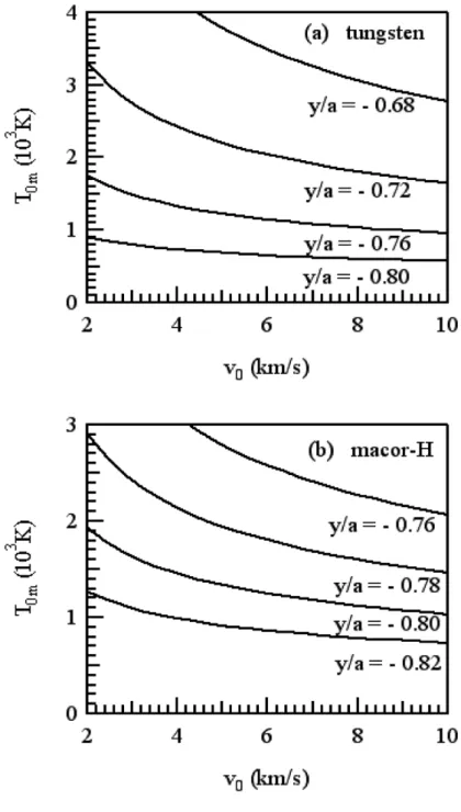
0= 8 km/ at the final stage of the flight (x/a = 1). We define T
0mas the maximum surface temperature of the FTP when the FTP travels from x = -a to x = a. The calculated T
0mare shown in Figs. 7 (a) and (b) for various values of v
0and y/a. It is seen that the maximum surface temperature of the FTP would not reach melting point when the FTP travels at y/a < - 0.68 for tungsten and y/a < -0.78 for macor-H with v
0> 4 km/s.
When the thickness of tungsten and macor-H is larger than rc, the temperature rise in the inner box of the FTP having the crystal oscillator and the CPU elements is smaller than 0.1 K. For example, when v
0= 10 km/s, r
c= 2.1 mm for tungsten and r
c= 0.8 mm for macor-H at t = 2a/v
0. Thus, the crystal oscillator and the CPU elements can keep the operation stable.
Fig. 5
Calculated surface temperature increases of (a) the tungsten plate and (b) the macor-H plate as a function
of x/a for various flight velocities, where A = 2, n
e0= 1 × 10
14, T
e0= 10 keV, T
i0= 10 keV, and δ
e= 0.2.
Fig. 6
Calculated surface temperature increases of (a) the tungsten plate and (b) the macor-H plate as a function
of x/a for various y/a values, where the flight velocity is 8 km/s, A = 2, n
e0= 1 × 10
14, T
e0= 10 keV, T
i0= 10
keV, and δ
e= 0.2.
18
Fig. 7
Calculated maximum surface temperature increases of (a) the tungsten plate and (b) the macor-H plate as
a function of flight velocity for various y/a values, where A = 2, n
e0= 1 × 10
14, T
e0= 10 keV, T
i0= 10 keV,
and δ
e= 0.2.
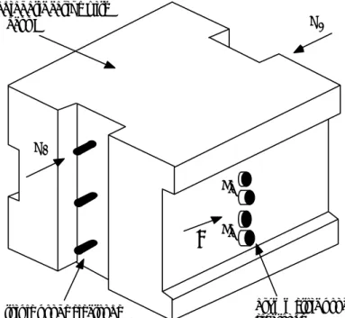
III. OBSERVATION METHOD
Figure 4 shows the bird’s-eye view of the FTP. This is the case of the EPCPU-1, where the triple probe and the differential double probe are buried in the low conductive insulator (macor H). All the electrodes made of high conductive material (tungsten) are placed in the shadow region in considering of the sheath effect. If we observe the current J
2, which is the current flowing anti- direction of the magnetic field line, we can also estimate the flow velocity. The size of this probe must be as small as possible to avoid the disturbance to the core plasma Three currents I
1, I
2and I
3in Fig. 2, which would be inductively excited in the loop coils when the plasma current flows in tokamak, generate voltages across the detection resistance during the flight and excites the crystal oscillator accompanying the rf signal, whose signal is simultaneously transmitted to the observer. The frequency of the oscillator is proportional to the excited voltage. The current of the MPRF-1 is superposed on the rf signal and we can estimate from this current the magnetic field profiles in the r,θ and z directions, these the values reflecting the poloidal magnetic field. When the Hall element is used for the detection of the poloidal magnetic field, some kinds of battery must be equipped inside the FTP.
Denoting I
aand I
bfor both currents in Fig. 4 we can evaluate T
ias
(5)
where Z is charge state, B is magnetic field L
pis the length of the differential double probe to the toroidal direction and A is the atomic number. The voltage is either positively or negatively biased in stationary state. It should be noted that the probe direction must be exactly in parallel to the magnetic field for the precise measurement of the ion temperature.
Using the value of T
iand V
fwe refer to a more exact expression of the space potential as
(6)
where the value of T
iis measured by the DDP while V
fand T
eare measured by the triple probe. Since the floating potential is equal to the space potential for the emissive probe, if one more circuit including the emissive probe having the heating coil can be
adiabatic casing with macor H
triple probe electrode J 1
J 2
I a
B I b
asymmetric probe electrode
Fig. 4
Bird’s-eye view of the EPCPU-1 of the FTP.
20
installed inside the EPCPU-1, we can measure the space potential directly. From the value of V
s, the radial electric field in plasma is evaluated by the relation of E
r= -∂Vs/ ∂r, which may be useful to study the H mode physics in the core plasma.
If the current J
1- J
2is obtained, the information of nkT
eand nkT
ias well as the information of the flow can be obtained. Even if T
eand T
iare not available to be measured due to the difficulty in voltage biasing, since the value of J
j( j=1.2) must be a function of nkT
eand nkT
iwe can estimate T
e, T
iand n as well as the flow where J
1and J
2are the currents parallel and anti-parallel currents to the magnetic field as shown in Fig. 4, respectively.
If we can observe the density and the potential fluctuations by the EPCPU-1 of the FTP, the study of the plasma transport must be advanced. In JFT-2M, where the transport has been investigated by using RPL [22], the use of FTP extends the measurement area over the whole region including the hot core plasma.
IV. DISCUSSION AND CONCLUSIONS
When we first considered the first time the idea of the FTP about 20 years ago, when the current profile could not measured in the large tokamak, then we designed the scale of the FTP is as large as a golf-ball which was too large to apply to be applied to the tokamak. However, the development of the memory storage has recently been developed to a greater degree of density. The scale of the memory density has been increased by 10
4times in the last fifteen years. This development makes it possible to realize such a mechanism as the FTP for the first time.
The flight mechanism is the rail gun type or the pellet injection. If an easier mechanism of the flight as well as the probe circuits is developed the FTP will be easily manufactured and the application to the large machine must become more convenient.
The installment of the global positioning system (GPS) would assure the FTP exact location, since the objective of the FTP is to know the exact profile of the plasma parameter exactly. However, it is not always necessary to equip the FTP with the GPS system, in the FTP since if the FTP can catch at the opposite port successfully the time behavior of the current would reflect the information of the position exactly.
Some kinds of condenser do not operate in some low pressure conditions, and when an over-voltage is applied to them the electrolytic liquid included will flow out. Therefore, the area of the condenser may be placed in an isolated pressurized box.
Since some kinds of ferrite must be included in the component of the CPU, a small Hall current may be generated in the circuit during the flight and the data would be damaged. It is necessary to remove such effects before manufacturing the FTP. If a timing device is necessary, it is possible to install this with small coils and resistors.
In conclusion, we have proposed a flight-type-probe for the measurement of high density and high temperature plasma in the core of fusion machines. If we can manufacture the compact FTP including the probe circuit and CPU memory with highly integrated way for the FTPs to fly with a speed of more than several km/sec keeping the angle of the electrode constant to the magnetic field, the FTP would survive in the hot plasma and yield the profiles of poloidal magnetic field, electron and ion temperatures, floating potential and fluctuations satisfactorily with a high spatial resolution. The use of FTP in hot and dense plasmas will open the frontier of the hot plasma confinement study.
ACKNOWLEDGEMENTS
We thank to N. Uchida and K. Hirai, Japan Advanced System Coop., and M. Hara, NEC Telnet works, for their technical support for the hardware of the FTP.
References
[1] K. Uehara, J. Plasma Fusion Res. 81 (2005) 483 (in Japanese).
[2] K. Makishima, T. Tominaga, H. Tohyama and S. Yoshikawa, Phys. Rev. Lett. 36 (1976) 142.
[3] K. McComick et al., Phys. Rev. Lett. 58 (1987) 491.
[4] F. M. Levinton et al., Rev. Sci. Instr. 61 (1990) 2914.
[5] H. Soltovich and H. R. Koslowski, Plasma Phys. Control Fusion 39, A341 ( 1997).
[6] For example, N. Asakura, S. Tsuji-Iio, Y. Ikeda, Y. Neyatani, and M. Seki, Rev. Sci. Instrum. 66 (1995) 5428.
[7] K. Oyama and K. Hirano, Planet Space Sci. 24 (1976) 900.
[8] H. Hirosawa, M. Ichikawa, Y. Kamata, K. Sagawa et al., Institutre of Space and Astronautical Science (ISAS) report vol.122 (2003).
[9] ITER Director, Summary of the ITER Final Design Report (2001).
[10] P.T. Lang, A. Lorentz et al., Nucl. Fusion 41 (2001) 1107.
[11] A. L. Brook, R.S. Hawke, J.K. Scudder and C.D. Wozynski, IEEE Trans. Mag-18 (1982) 68.
[12] http://www.ecliptek.com/crystals/#top
[13] B. M. Annaratone et al., Nucl. Fusion 34 (1994) 1453.
[14] H. Amemiya and K. Uehara, Jpn. J. Appl. Phys. 45 (2006) 247.
[15] K. Uehara et al., Jpn. J. Appl. Phys. 45 (2006) L630.
[16] E. Nakayama, S. Suzuki, I. Uchida and Y. Niimi, Yokogawagiho, 47, 111 (2003).
[17] Y. Kihara, K. Kuroiwa and Y. Ikeguchi, Toshiba Review, 59, 36 (2004).
[18] K. Yamaguchi, Y. Ueno and H. Nagasawa, Toshiba Review, 57, 22 (2002).
[19] http://focus.ti.com/docs/prod/folders/print/msp430f149.html
[20] P.C. Stabgeby, The Plasma Boundary of Magnetic Fusion Devices in Plasma Physics Series, Ed. P. Stott and Wilhelmsson (Institute of Physics Publishing, Bristol and Phyladelphia, 2000) p.649.
[21] T. Fujita et al., Phys. Rev. Lettt. 87 (2001) 245001-1.
[22] Y. Nagashima et al., Phys. Rev. Lett. 95 (2005) 095002.
1. 研究背景
流体の速度が流れる方向に対して垂直に勾配を持つ場合,これをフロー速度シアと呼ぶ.フロー速度シアは流体中 には必然的に存在するであろう一見単純な現象であるが,この現象が流体に Kelvin-Helmholtz 不安定性などの不安定 性をもたらすことが知られている[1] .これはプラズマに関しても言えることであり,特に磁化プラズマ中では外部 磁力線に垂直なフロー(主に E
r× B
zドリフト)の速度シア(垂直シア),及び平行なフローの速度シア(平行シア)
の2種類の速度シアが考えられ,一般にこれらはプラズマに異なる影響を与える.垂直シアは核融合プラズマ閉じ込 めの研究と非常に密接に関わっており,基礎研究においても長い間研究されている[2-4] .一方,平行シアについて は古くは 1960 年代に D’Angelo らにより D’Angelo モードと言われる不安定性の研究が行われた[5, 6] .彼らにより理 論的及び実験的研究がなされてはいるものの,平行シアの実験ではシア強度制御の困難さゆえ詳細な研究は実現され ず,それ以降,平行シア駆動/変調不安定性の実験は長らく行われなかった.しかし近年,地球周辺プラズマ研究にお ける平行シアの重要性が再認識されてきており,例えば極域電離圏で観測されたイオン音波不安定性に対して平行シ アを用いた理論モデルが提唱されている[7] .彼らの用いた分散関係からは,平行シア変調イオン音波と D’Angelo モ ードはそれぞれ異なる平行シアの符号において励起されることが導出される[8] .この平行シア変調イオン音波は実 験的に検証されている[9, 10] .
この様な状況において,東北大学ではQマシンの改良により世界に先駆けて平行シア強度及び垂直シア強度の制御 法を確立し[11],この手法を用いて平行・垂直シア駆動/変調低周波不安定性の実験的研究を推進してきた.上述し たイオン音波の議論は密度勾配のない場合にのみ一般性があると言え,すなわち密度勾配を考慮した場合にはイオン
フロー速度シア及び負イオンによるドリフト波の変調
市 來 龍 大,林 賢 一 郎,金 子 俊 郎,畠 山 力 三
*Influences of Plasma Flow Velocity Shear and Negative Ions on Drift Waves
By
Ryuta I CHIKI , Kenichiro H AYASHI , Toshiro K ANEKO , and Rikizo H ATAKEYAMA
*Abstract: The collisionless electron drift wave instability in a plasma involving sheared magnetic-field- aligned positive-ion flow and negative ion species has been experimentally investigated. We found that negative ions tend to stabilize the instability, which is the opposite result to a number of earlier studies on negative ion plasmas. The kinetic dispersion relation predicts that the current-driven shear-modified drift wave is excited for the positive shear range, and that the D’Angelo instability is brought about instead for the negative shear range. However, the wave observed is the current-driven shear-modified drift wave through both signs of the shear.
Key words: Flow velocity shear, Negative ion, Drift-wave instability, D’Angelo instability
*Tohoku University
音波の代わりにドリフト波を研究対象とする必要がある.そこで金子らは,ドリフト波不安定性が平行シアから受け る影響を実験的に観測し,その特性を運動論により説明した[12, 13] .さらに一般性を追求すべく,現在では平行シ ア・垂直シアの重畳効果の観測,及び多種イオンプラズマ系でのシア駆動/変調不安定性の研究を推進している.その 中の1テーマとして,宇宙プラズマには多種のイオンを含むプラズマや微粒子を含むプラズマが多く存在しているこ とを考慮に入れ,負イオン種を含むプラズマ(負イオンプラズマ)を用いた実験を行っており[14, 15] ,ここでは負 イオンプラズマ中における平行シア変調ドリフト波不安定性の実験に関して報告する.負イオンプラズマ中の平行シ ア実験は筆者の知る限りでは1例のみ存在し,An らがQマシンプラズマ中で観測された D’Angelo モードについて報 告している[16] .理論的には負イオンの導入が D’Angelo モードの成長率を増加させると予測され[17] ,彼らはその 負イオンによる不安定性助長特性を観測したと報告している.
我々はこれまでに以下の2つの結果を得ている.
●
負イオンの導入により,ドリフト波は全シア強度範囲において抑制された.
●
シア変調ドリフト波のみが観測され,D’Angelo モードは励起されなかった.
これらの結果についての詳細を報告する.
2. 実験装置
実験は東北大学の Q
T-Upgrade Machine を用いて行った.装置の概略を図 1(a) に示す.生成される磁化プラズマの各 パラメータはプラズマ密度 n 〜 _ 10
9cm
-3,電子・正イオン温度 T
e〜 _ T
i〜 _ 0.2 eV,プラズマ空間電位φ
s〜 _−6 V,プラ
ズマ直径 L 〜 _ 40 mm,磁場強度 |B| = 0.24 T である.このQマシンは沿磁力線正イオンフロー及びその速度シア(平行
シア)制御用に装備されている[11] .その特徴は以下の3点である. (1)カリウム正イオン(K
+)源であるタング ステンホットプレートが同心円状に分割されている. (2)真空容器端のもう一方に電子源用のタングステンホットプ レートが装着される. (3)正イオン源の前面に負にバイアスしたメッシュグリッドが配置される.
沿磁力線正イオンフローは図に示されるように正イオン源電位とプラズマ空間電位φ
sの差により発生させるため,
フロー速度制御はφ
sを固定した上で正イオン源電位を変化させて行う.ここでもし正イオン源からの熱電子がプラズ
空間電位
0 100
200
z [cm]
電子源 電子反射 正イオン源
グリッド Kオーブン
Vie1 Vie2 (1 V)
Vee (-2 V) Vg (-60 V)
K+
SF6- e- e-
e-
K+−SF6-−電子プラズマ
SF6 ガス
20mm 56mm 100mm
20mm
(a) (b)
間隙 3mm
図 1 (a) 平行シア制御用に装備された Q
T-Upgrade Machine の概略図.(b) 分割型タングステンホットプレート
(正イオン源)の概略図.内部より第1,第2,及び第3電極.
24
マに供給されれば,φ
sが正イオン源電位に引きずられ変化してしまいフロー速度制御は達成されないため,正イオン 源からの電子をメッシュグリッドにより反射する.プラズマを構成する電子は電子源から供給するため,φ
sは電子源 電位を一定にすることにより固定することができる.また,電子源からの熱電子は half-Maxwell 分布で放出されたの ちメッシュグリッド到達時に反射され逆方向に進むため,結果的に Maxwell 分布となる.
平行シアの生成についてであるが,図 1(b) のように正イオン源を同心円状に分割しているため,それぞれの部分に 独立にバイアスすることができ(正イオン源電位を内側から V
ie1,V
ie2で表す.なお,今回の実験では第3電極は使用 していない. ) ,すなわち各プラズマ層の沿磁力線正イオンフロー速度を独立に制御することができる.このとき,各 層(直径 20 mm の第1層,外径 56 mm の第2層)の境界に平行シアが生成・制御されることになる.今回の実験では V
ie2= 1 V に固定しており,第2層での K
+フロー速度はイオン音速 の 8 倍程度である.この速度と第1層で のフロー速度の差が平行シアを生むため,実験においてはシア強度の目安として電極電位差 Δ V
ie= V
ie2−V
ie1を用い る.
負イオン種生成のため,0.1 eV 程度の電子エネルギー領域において高い電子付着断面積を有する SF
6ガスをプラズ マ中に導入する[18] .結果的にプラズマは K
+− SF
6–−電子プラズマとなる.電子が負イオンに置き換わる割合(負 イオン交換率)ε= n_/n
+は,SF
6ガスの分圧を変えることにより制御する.
プラズマパラメータの測定及び揺動時系列の検出は,真空容器側面から挿入した Langmuir プローブを用いて行った.
沿磁力線 K
+フロー速度は静電イオンエネルギーアナライザーを用いて測定した.
3. ドリフト波不安定性の同定
プラズマ中に自己励起しているドリフト波が平行シア及び負イオンから受ける影響を報告していくわけであるが,
その前に,観測された揺動がドリフト波である証拠を3例挙げておく.
(A)電子反磁性ドリフト速度での周方向伝搬
(B)有限の沿磁力線(軸方向)波数の存在
(C)プラズマ密度勾配の急峻な場所での局所的励起
このうち, (A)及び(B)の波数測定に関してこの章で説明する.
図 2(a) のように先端に 4.5 mm の距離をおいた2つのプローブ端子を有するY型プローブをプラズマ円柱側面から挿 図 2 (a) Y型プローブ配置図.(b) Y型プローブにより検出した揺動位相差(上)及び電子飽和電流(下).
実線は k
‖= 0 を仮定した理論曲線であり,この曲線と陰影部以外の位相差データに差異があることよ り k
‖が有限の値を持つことが評価できる.
プラズマ 円柱断面 Y型プローブ
プローブ端子1
プラズマ円柱側面
プローブ端子2

![Fig. 1 Schematic design of the performance of the flight type probe (FTP), where the scale of plasma is assumed as that of ITER [9].](https://thumb-ap.123doks.com/thumbv2/123deta/6804463.2229348/16.892.181.722.126.443/schematic-design-performance-flight-probe-scale-plasma-assumed.webp)