Synthesis of ordered mesoporous carbons with channel structure from an organic organic nanocomposite
著者 Tanaka Shunsuke, Nishiyama Norikazu, Egashira Yasuyuki, Ueyama Korekazu
journal or
publication title
Chemical Communications
volume 2005
number 16
page range 2125‑2127
year 2005‑03‑08
URL http://hdl.handle.net/10112/5589
Synthesis of ordered mesoporous carbons with channel structure from an organic–organic nanocomposite{
Shunsuke Tanaka, Norikazu Nishiyama,* Yasuyuki Egashira and Korekazu Ueyama
Received (in Cambridge, UK) 27th January 2005, Accepted 8th March 2005 First published as an Advance Article on the web 17th March 2005
DOI: 10.1039/b501259g
Mesoporous carbons with ordered channel structure (COU-1) have been successfully fabricatedviaa direct carbonization of an organic–organic nanocomposite.
The discovery of nanostructured carbon materials such as fullerenes1 and carbon nanotubes2 has led to a considerable interest in the development of various carbonaceous materials. In particular, porous carbonaceous materials have been attracting much attention because of their high surface areas, large pore volumes, chemical inertness and high mechanical stability. Porous carbons show promise in the fields of hydrogen-storage, catalysis and electrochemistry. Many researchers have reported control of such pore structures through the template method, using various inorganic porous materials such as alumina membranes,3 zeolites,4–6siliceous opals7and silica xerogels.8Recently, various types of ordered mesoporous carbons (OMCs) have been generated viaa multistep synthetic procedure, in which ordered mesoporous silicas (OMSs) are employed as hard templates.9–15 The most common synthetic route yielding OMCs involves preparation of OMS templates, impregnation of the OMS pores with carbon precursors, carbonization, and removal of the templates (Fig. 1(A)). The removal of the OMS templates can be performed through a treatment with HF solution, converting the
carbon into a porous form, while retaining the nanostructural features of the OMSs.
In contrast, our novel OMC synthesis route, reported here, avoids the use of hard templates, and could thus reduce the number of preparation steps and the cost involved in producing these materials. Our strategy is to use an organic–organic interaction between a thermosetting polymer and a thermally- decomposable surfactant to form a periodic ordered nanocompo- site. The thermosetting polymer is carbonized by heating under N2, after which process it remains as a carbonaceous pore wall (Fig. 1(B)). Resorcinol/formaldehyde (RF) and triethyl orthoace- tate (EOA) were used as the carbon co-precursors and triblock copolymer Pluronic F127 was used as a surfactant (Fig. 1(C)). The resultant materials are referred to as COU-1.
In a typical synthesis, 0.661 g resorcinol was completely dissolved in a mixture composed of 1.74 g deionized water, 2.3 g ethanol and 0.06 ml hydrochloric acid (5 mol l21). Then, 0.378 g Pluronic F127 was added to the resorcinol solution. After the complete dissolution of the Pluronic F127, 0.487 g of triethyl orthoacetate and 0.541 g of formaldehyde was added to the solution, and stirred at 30uC for 20 min. The resultant solution was added dropwise to a silicon substrate spinning at 50 rpm, and then the substrate was spun up to 1000 rpm for 2 min. For polymerization of the resorcinol with formaldehyde, the as- deposited sample was heated at 90uC for 5 h, in air. Then, the resultant brown deposit was carbonized under a nitrogen atmo- sphere at 400uC for 3 h at a heating rate of 1uC min21, followed by further carbonization at 600 and 800uC for 3 h.
{Electronic supplementary information (ESI) available: XRD patterns, nitrogen adsorption/desorption isotherms, and pore size distributions of COU-1. See http://www.rsc.org/suppdata/cc/b5/b501259g/
Fig. 1 Schematic illustration of the synthesis routes for ordered mesoporous carbons. (A) Traditional impregnation synthesis route. (B, C) Direct synthesis route and co-carbon precursors in our work. (a) Self-assembly of silica precursor and surfactant. (b) Obtaining of OMSviaremoval of surfactant by pyrolysis or solvent extraction. (c) Impregnating pores of OMS template with carbon precursor. (d) Carbonization within pores of OMS. (e) Obtaining of OMCviaremoval of OMS by treatment with HF solution. (c9) Self-assembly of carbon precursor and surfactant. (d9) Obtaining of COU-1viaremoval of surfactant by direct carbonization.
COMMUNICATION www.rsc.org/chemcomm | ChemComm
This journal isßThe Royal Society of Chemistry 2005 Chem. Commun., 2005, 2125–2127 | 2125 Downloaded on 08 November 2011 Published on 17 March 2005 on http://pubs.rsc.org | doi:10.1039/B501259G
View Online / Journal Homepage / Table of Contents for this issue
The ordered structure of COU-1 was confirmed by X-ray diffraction (see ESI{for details). COU-1 on the silicon substrate showed a sharp reflection peak at 2h 5 0.9–1.3u. The periodic structure of the RF/EOA–F127 composite seems to be formed by an organic–organic interaction, similarly to the inorganic–organic interaction in mesostructured silicas. In the precursor solution, the functional groups of RF and EOA must be dissociated into negatively charged Ph–O2 and C–O2 species, respectively. The charged polymer chain must interact with the tails of the surfactant F127. The intense diffraction peaks for COU-1 at elevated carbonization temperatures show the retention of the periodic order of COU-1, but thedspacing shortened from 9.2 to 7.0 nm.
This result implies that condensation of the residual hydroxyl groups takes place in the carbonaceous walls at elevated temperatures. However, the full-width at half-maximum (FWHM) of the diffraction peaks scarcely changed, a result indicating that the periodic mesostructure is thermally stable and that its quality can be preserved at high temperatures. The peaks observed at 2h 525 and 45u are characteristic of the graphitic species in this carbon matrix.
The porous structures of the samples were investigated by nitrogen adsorption/desorption measurements (see ESI{ for details). Table 1 summarizes the results of the pore structure analysis for COU-1. The pore diameters of COU-1 carbonized at 400, 600 and 800uC were estimated to be 7.4, 6.2 and 5.9 nm, respectively. At relative pressures lower than 0.1, a large increase in the micropore volume was observed when the carbonization temperature was increased from 400 to 600 uC. The products carbonized at 600 and 800uC have high BET surface areas of 1274 and 1354 m2g21, respectively. COU-1 carbonized at 400uC had a low surface area of 624 m2g21. The surfactant F127 must have decomposed below 400 uC, because mesopores were already generated in the COU-1 carbonized at 400uC. The thermosetting RF polymer remained as the carbonaceous pore walls, while the Pluronic F127 decomposed to form the mesopores. The increase in the micropore volume and the BET surface area at 600 uC must be due to the generation of gases from the decomposition of the RF polymer. The chemical compositions (C and H) of carbonized samples were determined with a Perkin-Elmer 2400 II analyzer. The molar ratios of C/H were determined to be 23, 46 and 459 for the COU-1 samples carbonized at 400, 600 and 800uC, respectively. The large increase in the C/H ratio at 800uC indicates that the decomposition of the RF polymer still continued at 600–800 uC, although the micropore volume and the BET surface area showed no further increase above 600uC.
The carbonization of RF polymer without surfactant or with anionic and neutral surfactants resulted in low surface areas of 30–130 m2 g21.16 We found that the use of a precursor solution without EOA produced a poor periodic structure in the RF–F127 composite on a silicon substrate. The role of the EOA is uncertain; its addition apparently has a favorable effect on the stabilization of the periodic mesostructures of the RF/EOA–F127.
Table 1 Structural properties of COU-1 carbonized at different temperatures
Ta/uC d100b/ nm
SBETc/ m2g21
VTd/ cm3g21
De/ nm
C (wt%)f
H (wt%)g
400 9.2 624 0.738 7.4 63.6 2.8
600 7.5 1274 0.813 6.2 78.9 1.7
800 7.0 1354 0.743 5.9 82.6 0.2
aCarbonization temperature. bLattice d-spacing. cBrunauer–
Emmet–Teller (BET) surface area.dTotal pore volume calculated as the amount of nitrogen adsorbed at a relative pressure of 0.99.
ePore diameter calculated by the Barrett–Joyner–Halenda (BJH) method using adsorption branches. fCarbon content. gHydrogen content.
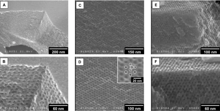
Fig. 2 FE-SEM images of carbonized COU-1. The carbonization temperatures were as follows: (A, B) 400uC, (C, D) 600uC and (E, F) 800uC.
2126 | Chem. Commun., 2005, 2125–2127 This journal isßThe Royal Society of Chemistry 2005 Downloaded on 08 November 2011 Published on 17 March 2005 on http://pubs.rsc.org | doi:10.1039/B501259G
View Online
Fig. 2(A)–(F) show FE-SEM images of a cross-section of COU-1. FE-SEM images were recorded on a Hitachi S-5000L microscope at an acceleration voltage of 21 kV. The samples were not coated before the FE-SEM measurements. Pores parallel to the film surface are evident in Fig. 2(A) and (B). The use of a silicon substrate as the support medium seems to aid the RF/
EOA–F127 composite to form a periodic mesostructure.
Hexagonally arranged pores are observed in Fig. 2(C) and (D).
The lattice spacing and pore diameter were estimated asca. 7.5 and 6.2 nm, respectively. The FE-SEM observations strongly support the results of the XRD and N2adsorption measurements. Ordered straight channels were visible in Fig. 2(E) and (F); such a channel structure has never before been seen in OMCs synthesized by the hard templating methods.
We believe that our direct method will expand the possibility of synthesizing a variety of ordered porous carbon structures.
The choice of an appropriate set of thermosetting polymers and surfactants is the most important factor in controlling the structure of these ordered mesostructured carbons. This direct synthetic route could facilitate the mass-production and creation of new carbon and carbon–polymer porous materials.
COU-1 materials should exhibit high performance in catalysis, adsorption, nanodevices and electrochemical double- layer capacitors.
The authors wish to thank the GHAS laboratory and Mr M. Kawashima (Osaka University) for FE-SEM measurements and Mrs F. Yano (Osaka University) for the elemental analysis.
Shunsuke Tanaka, Norikazu Nishiyama,*Yasuyuki Egashira and Korekazu Ueyama
Division of Chemical Engineering, Graduate School of Engineering Science, Osaka University, 1-3 Machikaneyama, Toyonaka, Osaka, 560- 8531, Japan. E-mail: [email protected];
Fax:+81 6 6850 6256; Tel:+81 6 6850 6256
Notes and references
1 H. W. Kroto, J. R. Heath, S. C. O’Brien, R. F. Curl and R. E. Smalley, Nature, 1985,318, 162.
2 S. Iijima,Nature, 1991,354, 56.
3 T. Kyotani, L. Tsai and A. Tomita,Chem. Mater., 1995,7, 1427.
4 T. Kyotani, T. Nagai, S. Inoue and A. Tomita,Chem. Mater., 1997,9, 609.
5 Z. Ma, T. Kyotani and A. Tomita,Chem. Commun., 2000, 2365.
6 Z. Ma, T. Kyotani and A. Tomita,Chem. Mater., 2001,13, 4413.
7 A. A. Zakhidov, R. H. Baughman, Z. Iqbal, C. Cui, I. Khayrullin, S. O. Dantas, J. Marti and V. G. Ralchenko,Science, 1998,282, 897.
8 A. B. Fuertes,Chem. Mater., 2004,16, 449.
9 R. Ryoo, S. H. Joo and S. Jun,J. Phys. Chem. B, 1999,103, 7743.
10 J. Lee, S. Yoon, T. Hyeon, S. M. Oh and K. B. Kim,Chem. Commun., 1999, 2177.
11 S. Jun, S. H. Joo, R. Ryoo, M. Kruk, M. Jaroniec, Z. Liu, T. Ohsuna and O. Terasaki,J. Am. Chem. Soc., 2000,122, 10712.
12 S. H. Joo, S. J. Choi, I. Oh, J. Kwak, Z. Liu, O. Terasaki and R. Ryoo, Nature, 2001,412, 169.
13 J. S. Lee, S. H. Joo and R. Ryoo,J. Am. Chem. Soc., 2002,124, 1156.
14 M. Kruk, M. Jaroniec, T.-W. Kim and R. Ryoo,Chem. Mater., 2003, 15, 2815.
15 B. Tian, S. Che, Z. Liu, X. Liu, W. Fan, T. Tatsumi, O. Terasaki and D. Zhao,Chem. Commun., 2003, 2726.
16 N. Nishiyama, T. Zheng, Y. Yamane, Y. Egashira and K. Ueyama, Carbon, 2004,43, 269.
This journal isßThe Royal Society of Chemistry 2005 Chem. Commun., 2005, 2125–2127 | 2127 Downloaded on 08 November 2011 Published on 17 March 2005 on http://pubs.rsc.org | doi:10.1039/B501259G
View Online