長崎大学工学部研究報告 第
41
巻 第76
号 平成23
年1
月プロペラファンの非一様な環状後流と離散周波数騒音
佐々木壮一
*
・福田雅治**
・向井将伍**
Relation between Discrete Frequency Noise and Non-homogenous Circular Wake of a Propeller Fan
by
Soichi SASAKI * , Masaharu FUKUDA ** , Shogo MUKAI **
In order to clarify relation between discrete frequency noise and non-homogenous circular wake of a propeller fan which is used in a rectangular casing, the characteristics of the propeller fans were analyzed by measurement of internal flow. The absolute velocity of main flow domain in the meridional plane of the propeller fan became 30 m/s while the velocity of the inclined plane in the case of 40 degree was decreased to 25 m/s. The velocity fluctuations on the vertical plane in the wake were weakened at the diagonal line of the duct by the velocity deformation formed to the circumferential direction around the impeller. Then the circular wake formed in the propeller fan was broken by the velocity deformation. It is considered that the discrete frequency noise of the propeller fan in the second harmonics became large because the fourteen dynamic rotors and the pseudo four stators made by the non-homogenous circular wake resonated.
Key words : Fan, Resonance, Aerodynamic Noise, Wake, Internal Flow
1.緒言
電子機器の筺体,エンジンケーシング,空調機 器の角ダクトなどで利用されるプロペラファン の後流は,円筒ダクトを基本形状とする軸流ファ ンのような軸対象の流れとは異なる様相になる.
例えば,軸流ファンの場合,設計点近傍での羽根 車後流の形状は環状になる.一方,矩形ダクトに 取り付けられたプロペラファンの後流はダクト 形状の影響を被る.このような回転軸に対して非 対称性のある後流には,その形状に依存した固有 の振動や騒音の発生が懸念される.リングファン は,このような矩形のケーシングを有すエンジン 冷却用ファンとして開発されたものである
(1)
.こ のファンの羽根車は,翼先端側にリング状のシュラウドを有す特徴がある.Longhouse
(2)
は,翼弦 長の6.5
%の翼先端隙間におけるリングファンの 騒音レベルが一般のベルマウスによるプロペラ ファンよりも最大12dB
低減されることを実験的 に明らかにしている.高山ら(3)
は,5
枚翼のプロ ペラファンの全周流れに対して,約650
万要素を 用いたLES
解析を実施している.同研究では,翼通過周波数成分の騒音を除けば,壁面近傍の格 子解像度上げることによって広帯域騒音の特性 をある程度捕らえることが可能であることが示 されている.著者ら
(4)
は,矩形のケーシングで利 用されるリングファンの性能に関する実験的な 研究に取り組んできた.これまでの研究で,リン グファンの効率は,従来のプロペラファンよりも平成22年12月16日受理
* 機械システム工学講座(Department of Mechanical Systems Engineering)
** 生産科学研究科博士前期課程(Graduate School Student, Graduate School of Science and Technology)
1
佐々木壮一,福田雅治,向井将伍
約
12
%向上すること,そのファン騒音は最高効 率点近傍で約3dB
低減されることなどを明らか にした.さらに,このファン騒音の特性には,離 散周波数騒音の影響が大きいことを指摘してい る.本研究では,プロペラファンの離散周波数騒 音とその後流に形成される環状の流れとの関係 を明らかにすることを目的として,二種類のプロ ペラファンの羽根車の後流と空力騒音の関係が 解析されている.これらの解析に基づいて,矩形 ダクトで利用されるプロペラファンの環状後流 の非一様性と離散周波数騒音の関係について議 論する.おもな記号
f
周波数(Hz)
D
羽根車外径(m) D hub
ハブ直径 (m)L
動力(W)
L
A 騒音レベル(dB) N 回転数 (rpm) P
s 静圧(Pa) Q
流量(m 3 /min) U 周速度 (m/s) x
主流方向距離(m) Z
羽根枚数φ 流量係数 ψs 静圧係数 ψt 全圧係数 λ 動力係数 η 効率
ρ 密度 (kg/m
3 )
ν ハブ比2,実験装置および測定方法
図
1
は供試羽根車の形状を示したものである.表
1
にその主要寸法が示されている.図1(a)
がプ ロペラファンの羽根車であり,図1(b)がリングフ
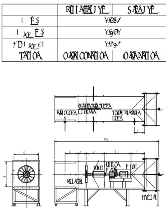
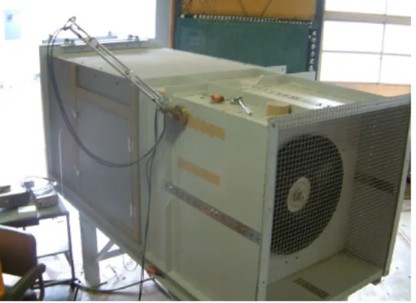
ァンの羽根車である.両者の羽根車はリングシュ ラウドの有無に相違があるだけで,その設計寸法 は同じである.羽根車の代表寸法には,プロペラ ファンの直径が採用されている.図2
はファン性 能の試験装置の概略図を示したものである.測定 胴の断面は1m×1m
の正方形であり,装置の全 長は約4m
である.ファンの空力特性の試験方法 については既報(4)で詳述されているので,本報で は割愛されている.送風機の静圧係数,流量係数,(a) Propeller fan
(b) Ring fan Fig. 1 Test impeller
Table 1 Main dimensions of test impeller Propeller Fan Ring Fan
D (m) 0.613
D hub (m) 0.260
ν = D hub / D 0.424
Shroud without shroud with shroud
1000
1000 500 300 700 1050 500
3990
400
Static Pressure Tube
Damper Torque
Meter Impeller
Motor Strut
5-hole Pitot Tube Hot-wire Pitot Tube
Fig .2 Experimental apparatus
2
プロペラファンの非一様な環状後流と離散周波数騒音
動力係数および効率は式(1)のように定義されて いる.
φ = 4Q / π ( 1-ν
2 ) D
2U
ψs= 2P
s/ ρ U 2
λ = 8L / ρ π ( 1-
ν 2 ) D 2 U 3 (1)
η = φψt/ λ
ここで,φは流量係数,ψ
s
は静圧係数,λは動 力 係 数 ,η は 効 率 で あ る . 主 軸 の 回 転 数 は1200rpm
となるようにインバータで制御されている.このとき,翼通過周波数は
280Hz
になる.図
3
はファン騒音の測定方法を示したものであ る.騒音は羽根車の回転軸上1.0m
上流側の点で,精密騒音計に取り付けられた
1/2
インチマイクロ ホンによって測定されている.精密騒音計からの 出力信号はFFT
アナライザ(小野測器;CF5210)
へ入力され,周波数分析された騒音スペクトルが 得られる.
図
4
には,内部流動の測定方法が示されている.羽根車の後流は熱線流速計によって測定されて
いる.傾斜断面にはプローブが専用のアダプタを 介して取り付けられている.その測定断面は主軸 に対して水平な子午面,子午面に対して
20°と 40
°傾いた傾斜断面(図5(a)
参照),および主流 に対して垂直な断面(図5(b)参照)である.垂直
断面での後流の計測では旋回流の影響が生じる.このため,この断面における速度分布には,水平 方向と垂直方向に張られたI型熱線で計測され た流れの平均値が採用されている.この傾斜断面 における主軸に対して垂直方向のスパン長さは,
傾斜角
20°のとき約 532mm
となり,40°のとき約
653mm
になる.主軸方向の測定点の間隔は50mm
であり,主軸と垂直方向には20mm
の間 隔が設定されている.3,実験結果および考察
図
6
はファンの空力特性を示したものである.○がプロペラファンの特性であり,●がリングフ ァンである.リングファンの静圧係数は,広い流 領域に渡ってプロペラファンよりも高くなった.
これに応じて,実測値の最高効率点近傍
(
φ =1000
Damper Torque
Meter Impeller
Motor Strut
Noise Level Meter
Fig. 3 Measurement method of fan noise
Fig. 4 Measurement method of internal flow in the inclined plane
z x y θ
(a) Meridional plane, Inclined plane
z x y
(b) Vertical plane
Fig. 5 Measurement plane of the fan
3
佐々木壮一,福田雅治,向井将伍
0.4 )でのリングファンの効率は,プロペラファン
よりも約12%
高くなった.図
7
には,ファンの騒音特性が示されている.リングファンのファン騒音は最高効率点近傍で,
プロペラファンよりも約
3dB
低減された.図8
は最高効率点近傍におけるファン騒音のスペク トル分布を示したものである.細い実線がプロペ ラファンの騒音スペクトルであり,太い実線がリ ン グ フ ァ ン の ス ペ ク ト ル で あ る .100Hz
か ら200Hz
近傍に分布するリングファンの広帯域騒音は,プロペラファンの騒音よりも大きい.一方,
いずれのファン騒音も離散周波数騒音が大きく,
翼通過周波数におけるリングファンの騒音はプ ロペラファンよりも小さくなった.図
7
のファン 騒音の特性を勘案すれば,離散周波数騒音がファ ン騒音の支配的因子になることがわかる.図9
に は,各高調波次数における両者のファン騒音の差 が整理されている.プロペラファンの第二高調波 での離散周波数騒音レベルはリングファンよりも
9.8dB
高くなった.以下の内部流動の解析では,このように特定の高調波次数でプロペラファン の離散周波数騒音が大きくなる現象について議 論する.
図
10
は子午面と傾斜断面における後流の速度 分布を示したものである.図10(a)
がプロペラフ ァンの速度分布であり,図10(b)がリングファン
である.流量は最高効率点(φ= 0.4
)に設定さ れている.これら二つの内部流動に関する基本的 な性質につては既報に詳述されているので,文献(4)
などを参考にされたい.この断面における速い 速度の領域を主流部と呼ぶことにする.プロペラ ファンの傾斜断面における主流部の速度は,その 傾斜角が大きくなるに従って減速される.これは 傾斜角のついた二次元の流路が拡大されるため に,局所的な流速が減速されるためであると考え られる.一方,リングファンの後流の流路はシュ ラウドによって一定に保たれるため,その主流部 には傾斜角によらずほぼ一様な速度分布が形成0 0.2 0.4 0.6 0.8
0 0.2 0.4 0.6 0.8 1.0
0 0.1 0.2 0.3 0.4 0.5 0.6
φ
η
N = 1200 rpm Z = 14
φ = 0.4
Propeller Fan Ring Fan
ψ
sη
ψ
sFig. 6 Aerodynamic characteristics of the propeller fans
0 0.2 0.4 0.6 0.8
70 80 90 100
φ L A , d B (A )
Propeller Fan Ring Fan
N = 1200 rpm Z = 14
φ = 0.4
Fig. 7 Noise characteristics of the propeller fans
10 1 10 2 10 3 10 4
0 50
100 N = 1200 rpm
Z = 14 φ = 0.4
Propeller Fan Ring Fan
n = 1 ( f = 280 Hz ) n = 2
n = 3 n = 4
Background Noise ( 48.1 dB )
f , Hz L A , d B (A )
Fig. 8 Noise spectra of the propeller fans
1 2 3 4 5
0 5.0 10.0
Δ L A , d B (A )
n ( mode )
N = 1200 rpm Z = 14 φ = 0.4
Fig. 9 Difference of the discrete frequency noise
4
プロペラファンの非一様な環状後流と離散周波数騒音
される.
図
11
は垂直断面の速度変動の分布が示されて いる.測定位置は羽根車の後縁から200mm
後方 の位置である.プロペラファンの速度変動の分布 では,ダクトの対角線上の速度変動が小さくなっ ており,環状の後流には四箇所の破れが形成されている.一方,リングファンの後流の速度変動は, プロペラファンよりも半径方向外側へ広がった 分布となり,環状に形成される後流の速度変動は 一様に分布している.図
10
の速度分布によれば,プロペラファンのダクト対角線上の速度は,その 流路が拡大されるために減速した.従って,プロ
0 100 200 300 400 500
0 100 200 300 400 500
1010 15 15
15 20
20 25 30
0 100 200 300 400 500
0 100 200 300 400 500
1010 15 15
15 20
20 25 30 Tip side
Hub side ηmaxpoint N= 1200 rpm θ= 0 °
x , mm
r , mm
0 100 200 300 400 500
0 100 200 300 400 500
1010 15
15 20
20 30 25 10
ηmaxpoint N= 1200 rpm θ= 20 ° Hub side
x , mm
r , m m
Tip side
0 100 200 300 400 500 600
0 100 200 300 400 500
1010 1010
15
15 20
20 25
ηmaxpoint N= 1200 rpm θ= 40 ° Hub side
x , mm
r , m m
Tip side
(a) Propeller fan
0 100 200 300 400 500
0 100 200 300 400 500
55 10
10 15
2015 25
0 100 200 300 400 500
0 100 200 300 400 500
55 10
10 15
2015 25
x , mm
r , m m
Hub side
ηmaxpoint N= 1200 rpm θ= 0 ° Tip side
0 100 200 300 400 500
0 100 200 300 400 500
55 10
10 15
15 20
20 25
ηmaxpoint N= 1200 rpm θ= 20 °
x , mm
r , mm
Hub side Tip side
0 100 200 300 400 500 600
0 100 200 300 400 500
5 510
10 15
15 20 25
ηmaxpoint N= 1200 rpm θ= 40 ° Hub side
x , mm
r , mm
Tip side
(b) Ring fan
Fig. 10 Distribution of the velocity in meridional plane and inclined plane
0 100 200 300 400 0 100 200 300 400 500 500
3 3
3.5 3.5 3.5
3.5
3.5 3.54
4
4 4.5
4.5 4.5
5
55 5.5
5.5
3 3
4 2.5
3.5 2.5
4.5 5.5
5 5
2.5 2.5
3 2.5
3
2.5 3.5
0 100 200 300 400
500
-500 -400 -300 -200 -100 03 3
3 3
3
3.5 3.5
3.5
3.5 3.5 3.5
4
4 4
4
4.5 4.5 4.55
5 5 5.5 5.5 3.5
2.5 2.5
3 2.5
2.5 4
5 3.5 5.5 2.5
-500 -400 -300 -200 -100 0
-500 -400 -300 -200 -100 0
3 3
3.5
3.5
3.5
3.5
3.5 3.5
4
4
4 4.5
4.5 4.5 5 5
5 5.5
5.5 3.5
3 3
2.5
3 2.5
2.5 3
2.5 3.54 5
2.5 5.5 4.55
2.5
-500 -400 -300 -200 -100 0
0 100 200 300 400 500
3
3 3
3 3
3.5
3.5 3.5
3.5 3.5 3.5
4
4 4
4 4.5
4.5
54.5 5 5
5.5 5.5 4
2.5 3.5
2.5 5.5
5
2.5 3
2.5 2.5
η
maxpoint
3.5N = 1200 rpm
0 100 200 300 400 0 100 200 300 400 500 500
2 3 4
4 4
5
5 5
5 5
4 3
5 3
6
-500 -400 -300 -200 -100 0
0 100 200 300 400 500
2 3
4
4 4
5
5 5 5
5 5 4
3 5
3 6
5
-500 -400 -300 -200 -100 0
-500 -400 -300 -200 -100 0
3 2 4
4
4 5
5 5
5
3 6
5
3 4 5
0 100 200 300 400
500
-500 -400 -300 -200 -100 03 2 4
4
4
5
5
5 5
3
5
6 4 5 3
5 5
η
maxpoint N = 1200 rpm
(a) Propeller fan (b) Ring fan Fig. 11 Distribution of the velocity fluctuation in vertical plane
5
佐々木壮一,福田雅治,向井将伍
ペラファンの垂直断面におけるダクト対角線上 の速度変動の分布には,この周方向の速度ひずみ によって破れが形成される.一方,リングファン の場合,羽根車の後流はそのシュラウドによって 矩形ダクトに流路の影響を受けにくくなる.これ に応じて,リングファンの後流には一様な環状後 流が形成される.非一様な環状後流がプロペラフ ァンに形成されるため,矩形ダクトの内部には擬 似的に
4
枚の静翼が形成される.この4
枚の静翼 と14
枚の動翼が干渉すると,1200rpm
で回転す る羽根車には560Hz
で共振現象が生じる.プロペ ラファンの第二高調波(f = 560Hz
)の離散周波 数騒音が増幅されることは,この擬似的な4
枚の 静翼との共振現象によるものであることを示し た.4,結言
矩形ダクトで利用されるプロペラファンの非 一様な環状後流と離散周波数騒音の関係につい て解析した結果,以下の結論が得られた.
(1)
本研究の実験条件では,プロペラファンの第 二高調波における離散周波数騒音レベルは リングファンよりも9.8dB
高くなった.(2)
プロペラファンの傾斜断面における主流部 の速度は,その傾斜角が大きくなるに従って 減速される.これは傾斜角のついた二次元の 流路が拡大されるために,局所的な流速が減 速されるためである.(3)
プロペラファンの速度変動の分布は,矩形ダ クトの対角線上で小さくなっており,環状の 後流には四箇所の破れが形成された.プロペ ラファンの垂直断面における非一様な環状 後流の分布は,周方向の速度ひずみによって 形成される.(4)
擬似的に形成される4
枚の静翼が14
枚の動 翼と干渉すると,1200rpm
で回転する羽根車には
560Hz
で共振現象が生じる.プロペラファンの第二高調波の離散周波数騒音は,この 擬似的な
4
枚の静翼との共振現象によって増 幅されることを示した.参考文献