Synchronization Phenomena and Oscillations Stopping in Coupled van der Pol with Diodes
Yuya Ikezoe Toshiya Matsunashi Yoko Uwate Yoshifumi Nishio Dept. of Electrical and Electronic Eng., Tokushima University
2-1 Minami-Josanjima, Tokushima 770–8506, Japan Email:{ikezoe, matsunashi, uwate, nishio}@ee.tokushima-u.ac.jp
Abstract—We investigate synchronization phenomena in van der Pol oscillators. We compare the coupled systems. Systems are four van der Pol oscillations coupled with diodes and resistors.
In this study, the diode is assumed that it shows cubic function.
We investigate the difference between the coupled systems. And we investigate that stop oscillation partially.
I. INTRODUCTION
Synchronization phenomena observe around us. For ex- ample, beat of the heart, firefly luminescence, cry of birds, and so on. Synchronization phenomena are used for these mathematical models. Therefore, they have been studied in various fields (Biology, Network systems ...)
We use van der Pol oscillators. Synchronization can be produced it by circuits. Because it is easy to observe the synchronization phenomena of van der Pol oscillators by changing frequency. This circuit is superior that it can fit products immediately.
The van der Pol oscillator is a simple circuit. It is consisted of resistor, inductor, capacitor and nonlinear resistor. Equation assumed that second‐order differential equation.
We use the coupled van der Pol systems. Four van der Pol oscillations coupled with diodes and resistors. And resistor and diode have coupling strength each. The coupled model in the only resistors have been studied [1],[2].
In this study, we investigate synchronization phenomena of van der Pol oscillators coupled models. And we compare the systems. This study has two purposes. The first, we find out the differences of synchronization phenomena between resistors and diodes. The second, we verify oscillation stop partially by changing the coupling strength.
II. SYSTEN MODELS
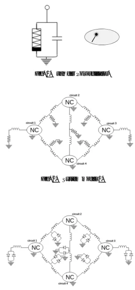
Figure 1 shows basic van der Pol oscillator. Figures 2 and 3 show system models constituted van der Pol oscillators (VDP). We use a ring of van der Pol osciilators, four VDP are connected by resistors or diodes. Figure 2 is all VDP coupled with resistors, but Fig. 3 is coupled with diodes. Figures 4 and 5 show system models coupled with resistors and diodes.
We investigate synchronization phenomena, how changing synchronization phenomena by the connection method.
= NC
Fig. 1. van der Pol oscillator.
Fig. 2. System model 1.
Fig. 3. System model 2.
The normalized equations of VDP circuit connected with resistors are given as follows:
˙
xj = ε(xj−x3j)−yja−yjb−yjc
˙
yja = −β3(yja+ylb) +x3j
˙
yjb = −β3(yjb+yla) +x3j
˙
yjc = −β3(yjc) +x3j.
(1)
- 80 -
IEEE Workshop on Nonlinear Circuit Networks December 7-8, 2018
Fig. 4. System model 3.
Fig. 5. System model 4.
˙
xk = ε(xk−x3k)−yka−ykb−ykc
˙
yka = −β3(yka+ynb) +x3k
˙
ykb = −β3(ykb+yna) +x3k
˙
ykc = −β3(ykc+ymc) +x3k.
(2) {
β=R
√C
L (3)
The normalized equations of VDP circuit connected with diodes are given as follows:
˙
xj = ε(xj−x3j)−yja−yjb−yjc
˙
yja = −γ3√3
yja+ylb+x3j
˙
yjb = −γ3√3
yjb+yla+x3j
˙
yjc = −γ3√3
yjc+x3j.
(4)
˙
xk = ε(xk−x3k)−yka−ykb−ykc
˙
yka = −γ3√3
yka+ynb+x3k
˙
ykb = −γ3√3
ykb+yna+x3k
˙
ykc = −γ3 3
√ykc+ymc+x3k.
(5) {
γ= 3
√ Lg3
Cgg1
(6)
Nonlinear resistorare defined as follows:
ign = −g1vn+g3vn3 (7) In these equations, j and k are the numbers of circuit.
Parametersl,n,mare related tojandk.j=1l=2,4,j=3l=4,2, k=2n=3,1m=4,k=4n=1,3m=2.εdenotes the nonlinearity of the oscillators. Figures 6 and 7 show systems which observe oscillations stop by the change of the parameterγ.
Fig. 6. System model 5.
Fig. 7. System model 6.
III. SIMULATION RESULTS
The simulation results of the system model are shown from Fig. 8 to 11. The value of the parameter is set to ε= 0.05, β = 0.005,γ= 0.005.
Circuit1-3 shows in-phase, and circuit1-2 shows anti-phase in Fig. 8. Figures 8 and 9 show almost the same synchroniza- tion phenomena. It shows there are few differences between models. The coupling schema is changed from resistors to diodes partially in Fig. 10. Circuit2-3, and circuit1-4 show in- phase synchronization phenomena in Fig. 10. The others are synchronized at anti-phase.
Circuit1-3, circuit3-4 show in-phase, and circuit2-3 shows anti-phase in Fig. 11. It shows s partial change causes the differences of synchronization phenomena.
x3 x4
x2 x1
x2 x2
x3 x1
x4 x3
x4 x1
Fig. 8. Phase differences of system 1.
x1
x3 x4
x2 x1
x2 x2
x3 x1
x4 x3
x4 Fig. 9. Phase differences of system 2.
x1
x3 x4
x2 x1
x2 x2
x3 x1
x4 x3
x4 Fig. 10. Phase differences of system 3.
x1
x3 x4
x2 x1
x2 x2
x3 x1
x4 x3
x4 Fig. 11. Phase differences of system 4.
- 81 -
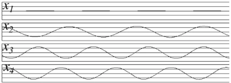
Next simulation results of the system model 5 ,6 are shown by Figs. 12 to 13. Horizon axis indicates timeτin Fig. 12 and 13. The value of the parameters is set toε= 0.05,β= 0.005.
Parameterγ is variable. The value of parameter ofγis set to γ=0.08 in Fig. 12, γ=0.135 in Fig. 13.
Figure 12 shows wave3 stop oscillation. The others continue to oscillate. Figure 13 shows wave1 and wave4 stop oscillation.
So these circuits make stopping oscillation partially.
Fig. 12. Stopping oscillation of systems 5.
Fig. 13. Stoppng oscillation of system 6.
IV. CONCLUSION
We have proposed a system model using a ring of four van der Pol oscillators coupled by resistors and diodes. We can observe various synchronization phenomena by changing resistors into diodes partially. When all resistors change into diodes, these synchronization phenomena show almost the same. However, when we change resistors into diodes partially, we observe the difference synchronization phenomena by changing only one part. We will investigate the synchroniza- tion phenomena using difference system model with diodes.
We observe oscillation stop partially. Future work, we measure data of the amplitude, and sort the date. We would like to presume a parameter and oscillatory relations.
REFERENCES
[1] Yoko UWATE, Yoshifumi NISHIO and Ruedi STOOP ”Synchronization in Two Polygonal Oscillatory Networks Sharing a Branch” Proceedings of International Workshop on Nonlinear Dynamics of Electronic Systems (NDES’10), pp. 62-65, May 2010.
[2] Yoko UWATE and Yoshifumi NISHIO ”Synchronizing Coupled Oscil- lators in Polygonal Networks with Frustration” Proceedings of IEEE International Symposium on Circuits and Systems (ISCAS’11), pp. 745- 748, May 2011.