九州大学学術情報リポジトリ
Kyushu University Institutional Repository
海中に流体を排出する片支持管の非線形振動解析
孟, 帥
http://hdl.handle.net/2324/1398372
出版情報:Kyushu University, 2013, 博士(工学), 課程博士 バージョン:
権利関係:
KYUSHU UNIVERSITY
Doctoral Thesis
Nonlinear Vibration Analysis of a Cantilevered Pipe Discharging Fluid in the Sea
Shuai Meng
Dissertation Submitted to Kyushu University In Fulfilment of the Requirements
For the Degree of Doctor of Philosophy
August 2013
Abstract
Ocean carbon dioxide sequestration has been recognized as a CCS (Carbon dioxide Capture and Storage) strategy in an attempt to reduce the threat of global warming.
Kyushu University launched carbon dioxide sequestration research as one department in I2CNER (International Institute for Carbon-Neutral Energy Research) in 2010 Dec. For ocean CCS realization, apart from the assessments of the environmental impacts (e.g.
ecological impact), one of the unanswered issues is the risk and stability of the carbon dioxide injection system. Thus, the present research has been motivated to investigate the nonlinear dynamics of a cantilevered pipe discharging fluid in the sea. The motiva- tion and the objective of this research are introduced in Chapter 1.
A great many efforts have been dedicated to the study on the fluid structure inter- action (FSI) area. On the one hand, dynamics of a fluid-conveying pipe in the air under various boundary conditions have been extensively studied experimentally and theoreti- cally. There is a consensus on the stability of a cantilevered pipe discharging fluid in the air. However, theory prediction contradicts the experiment observation on the stability of a free-hanging pipe aspirating fluid in water. Researchers are trying to explain this contradiction, but it is still one of the unresolved issues in FSI. On the other hand, dy- namics of marine riser systems have been widely investigated. With the increased focus on offshore oil and gas resources into deeper and harsher environments, internal flow effect has attracted greater attention over the last decades. Riser retrieval and ocean mining projects have motivated researchers to investigate the dynamics of a cantilevered riser exposed to external excitations. Chapter 2 makes an extensive literature review, which would be of great significance to find the influential factors that should be taken into consideration in the present study. For example, for a cantilevered marine riser, the effect of vortex induced vibration (VIV) on the amplified drag coefficient and the coupling effect between the drag force and lift force should be carefully considered.
In Chapter 3, the three-dimensional (3-D) nonlinear motion equations of a can- tilevered pipe discharging fluid with a lower marine riser package are derived based on modified Hamilton’s Principle in a rigorous way taking account of the effects of in- ternal flow, VIV, nozzle induced tensile force, a bottom end-mass, and the fact that the displacements vary along the span. The lower package is assumed to be a point mass and incorporated into the motion equations rather than in the boundary conditions.
The author proposes a new model to account for the coupling of the drag force and lift force. The Morrison formula is adopted to calculate the mean drag and viscous damping forces in both in-line (IL) and cross-flow (CF) directions. A model using double Duffing and van der Pol oscillators is employed for the 2-D VIV effect. The strains in IL and CF directions are assumed to be small recorded as the first order and the final 3-D motion
ii The resulting 3-D nonlinear structural equations can be discretized by Galerkin method adopting the eigenfunctions of a cantilevered beam as the comparison functions and then can be solved by Houbolt’s finite difference method and Newton-Raphson method. The 2-D wake oscillator model can be solved by Houbolt’s finite difference method and yield a new set of reduced vortex coefficients. The structural model is cou- pled with the VIV model. A flow chart of adopted solution methods is proposed and a MATLAB program is developed.
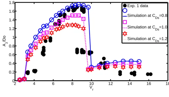
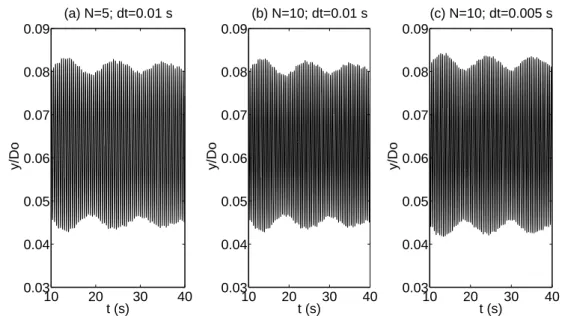
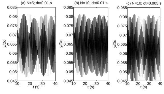
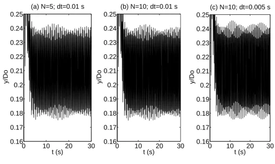
Chapter 4 is dedicated to validating the derived mathematical model and the pro- posed solution methods. It makes use of an experiment employing a cantilevered cylin- der which is free to move in both IL and CF directions denoted as Exp. 1. Simulations adopting wake coefficientsy =z= 0.3 are performed, wherey andzare the wake co- efficients in the IL and CF directions respectively. Convergent solutions can be achieved if enough mode functions and sufficiently small step-size are adopted under both lock- in and unlock-in conditions. The simulations can predict the CF amplitudes very well compared with the CF measurements in Exp. 1. The predicted CF amplitudes decrease with the increase of mean drag coefficient while keeping the same lock-in region. The simulations can capture the main dynamic characteristics of 2-D VIV after comparisons with former experimental observations.
Recently, a new set of wake coefficients has been calibrated based on 2-D VIV study, in which y = 0.3 and z =f(m∗), wherem∗ is the ratio of cylinder’s mass with inner fluid to the mass of the displaced external fluid. There is a need to test this newly calibrated wake coefficients in our derived motion equations with proposed solution methods. Making use of the Exp. 1 again, the simulations can yield acceptable results in the CF direction. The simulations can predict the CF amplitudes and the size of lock-in region. However, the onset of lock-in is predicted earlier at smaller reduced ve- locity compared with the Exp. 1. In order to explain the disagreements, the author finds that this new set of wake coefficients was calibrated utilizing experiments based on a mass-spring-damper model which is denoted as Exp. 2. It has been found that the CF measurements in Exp. 1 and Exp. 2 compare very well at the same mass ratio and similar damping ratio. It agrees with traditional Griffin plot and there might be some underlying relevance between a cantilevered cylinder and a mass-spring-damper model at the same mass ratio and damping ratio. Because there is no IL measurements in Exp. 1, the IL data in Exp. 2 are then utilized. Using the parameters from Exp.
1 and employing y = z = 0.3, the simulation can predict the IL lock-in region very well but fails to predict the IL amplitude, which is acceptable because this set of wake coefficient was derived based on 1-D VIV study (i.e. CF direction). The predicted IL amplitudes decrease with the increase of mean drag coefficient keeping the same lock-in region, which means that this set of wake coefficient can still be used for 2-D parametric study. Using the parameters from Exp. 1 and employing y = 0.3 andz =f(m∗), the
iii simulations can predict the amplitudes and size of lock-in region in the IL direction.
However, the onset of IL lock-in is predicted earlier at smaller reduced velocity compare with Exp. 2. These are the same as the observations when compared with the CF data in Exp. 1 by use of this new set of wake coefficients.
Driven by the carbon dioxide sequestration programme and the requirements to figure out whether the simulations can capture the effects of essential parameters, simulation studies employing y =z = 0.3 are performed in Chapter 5 to analyse the effects of a bottom end-mass, internal flow velocity and nozzle-induced tensile force.
Blevins and Coughran performed 1-D and 2-D VIV experimental study for paramet- ric investigations, which is denoted as Exp. 3. According to the simulation study, a larger end-mass narrows the lock-in region and causes the onset of lock-in to smaller reduced velocity. These are the same as the effects of a larger mass ratio in the 2-D VIV study in Exp. 3. However, contrary to the conclusion in Exp. 3, the maximum amplitudes keep almost the same at different end-masses, which is in consistent with the former VIV study of very long pipes with a bottom end-mass for application to deep ocean-mining lift pipes. Possible explanations are given in Chapter 5.
In order to investigate the effects of internal flow velocity and nozzle induced tension, a highly flexible and neutrally buoyant pipe system is selected. It is still of practical significance because long marine risers would behave like a highly flexible and slender structure. Simulations employing y =z = 0.3 are performed and summarized as fol- lows. (1) The pipe is inclined to lose energy to the internal fluid from the bottom end, the same as a cantilevered pipe aspirating water in former studies. (2) The CF ampli- tude decreases with the increase of inner flow speed. The internal fluid velocity also decreases the IL fluctuating oscillation amplitude but the effect is not obvious at large static displacement conditions which means the static displacement becomes dominant in the internal flow induced energy formula. (3) The static displacement increases with the increase of internal flow velocity, which means the internal flow can soften the pipe.
However, at sufficiently large static displacements and high internal flow velocities, the static displacement may decrease as the increase of inner flow speed. That means the energy lost at the bottom end due to the internal flow may be dominant compared to the current induced energy. (4) The nozzle induced tensile force can decrease the static displacement to stabilize the pipe system. However, this force has little effect on the CF vibration amplitude and IL fluctuating vibration amplitude. Because the tensile force is assumed to work only in the axial direction for simplicity in this study, more accurate conclusions can be drawn if the tension is assumed to take effect in three directions in future study. This parametric simulation study may provide to be a workbench for future simulation study and/or experimental investigations.
In Chapter 6, the contributions of this research are summarized and works for future
Acknowledgements
First and foremost, the author is deeply grateful to the supervisor Prof. H.Kajiwara for his patience, kindness, fruitful guidance, continuous encouragement and constant support in the course of this Ph.D work.
The author gratefully acknowledges the support of the International Special Course on Environment Systems Engineering, sponsored by the Japanese Ministry of Educa- tion, Culture, Sports, Science and Technology.
The author would like to express gratitudes to Profs. M.P. Pa¨ıdoussis, C. Semler et al. at McGill University. The author has benefited very much from the two comprehen- sive and indispensable books on fluid-structure interaction which are full of remarkable insights written by M.P.Pa¨ıdoussis. The author has learned a lot from the papers pub- lished by M.P.Pa¨ıdoussis, C. Semler et al.
The author also greatly appreciates Prof. C.H.K. Williamson (at Cornell University), Prof. P.W. Bearman (at Imperial College London), Prof. M. Patel (at Cranfield Univer- sity) and Prof. J.S. Chung (at ISOPE) for the fruitful discussions and their constructive suggestions. Sincere thanks are forwarded to them for their kind supports.
The author would appreciate Profs. T.Yoshikawa and M.Nakamura for reviewing the thesis and insightful comments.
Finally, the author acknowledges all the members at the system planning laboratory for their help and availability. They make me really enjoy working on this Ph.D project.
My gratitude to my parents, brothers and elder sister is beyond words. Their support is an anchor to help me undergo ups and downs in the past three years.
Meng Shuai
Kyushu University, August 2013
Contents
Abstract i
Acknowledgements iv
List of Figures vii
List of Tables ix
1 Introduction 1
1.1 Research background . . . 1
1.2 Research objective . . . 2
1.3 Outline of this thesis . . . 4
2 Literature Review 6 2.1 Introduction . . . 6
2.2 Dynamics of fluid-conveying pipes . . . 6
2.2.1 Modelling methods and instability forms . . . 7
2.2.2 Analysis methods . . . 13
2.3 Dynamics of a cantilevered pipe aspirating fluid . . . 14
2.4 Dynamics of marine risers . . . 16
2.4.1 Dynamic analysis of rigid risers . . . 16
2.4.2 Dynamic analysis of flexible risers and cables . . . 18
2.4.3 Dynamic analysis of a deep ocean mining pipe system . . . 20
2.4.4 Dynamic analysis of a cantilevered marine riser . . . 22
2.5 Vortex induced vibration . . . 24
2.5.1 Wake formation . . . 25
2.5.2 Griffin plot . . . 25
2.5.3 1-DOF VIV study . . . 25
2.5.4 2-DOF VIV study . . . 27
2.5.5 Parametric study . . . 28
2.5.6 VIV prediction model . . . 29
2.5.7 State of art . . . 31
2.6 Conclusion . . . 31
3 Derivation of Motion Equations 33
Contents vi
3.1 Introduction . . . 33
3.2 Derivation of 3-D motion equations based on modified Hamilton principle 34 3.2.1 Coordinate systems . . . 34
3.2.2 Kinetic energy of a plain pipe . . . 36
3.2.3 Potential energy of a plain pipe . . . 37
3.2.4 Energy of an end-mass . . . 38
3.2.5 Pressure energy . . . 39
3.2.6 Virtual work due to virtual momentum transport . . . 41
3.2.7 Virtual work due to hydrodynamic force . . . 42
3.2.8 Final equations . . . 49
3.3 Boundary conditions . . . 50
3.4 Solution methods . . . 51
3.5 Conclusions . . . 53
4 Simulation and Validation 55 4.1 Introduction . . . 55
4.2 Simulation and validation . . . 60
4.3 Conclusions . . . 72
5 Parametric Study 74 5.1 Introduction . . . 74
5.2 Effect of a bottom end-mass . . . 74
5.3 Internal flow effects . . . 77
5.4 Nozzle effect . . . 80
5.5 Conclusions . . . 81
6 Conclusion 88 6.1 Conclusion . . . 88
6.2 Future work . . . 89
A Derivation of Motion Equations 91
Bibliography 105
List of Figures
1.1 Ocean CCS diagram . . . 1
1.2 Diagram of the oceanic sequestration research at I2CNER . . . 2
2.1 A nozzle configuration . . . 12
2.2 The classical Feng-type VIV response . . . 26
2.3 1-DOF VIV response at small m∗ζ . . . 27
2.4 Former coupling model in 2-DOF VIV study . . . 30
3.1 The configuration of the pipe system for oceanic sequestration research at I2CNER . . . 33
3.2 Coordinate system . . . 34
3.3 Nozzle effect . . . 40
3.4 The expected deformation shape of the pipe system . . . 41
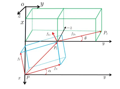
3.5 The proposed modeo for the hydrodynamic forces . . . 48
3.6 Flow chart of numerical methods . . . 52
4.1 An experimental set-up based on a mass-spring-damper model . . . 59
4.2 Comparisons between simulations employing y = z = 0.3 and experi- ments in the CF direction . . . 64
4.3 Trajectory of the bottom end . . . 64
4.4 Convergence tests in the IL direction before the onset of lock-in . . . 65
4.5 Convergence tests in the CF direction before the onset of lock-in . . . 65
4.6 Convergence tests in the IL direction at the onset of lock-in . . . 66
4.7 Convergence tests in the CF direction at the onset of lock-in . . . 66
4.8 Convergence tests in the IL direction in the lock-in region . . . 67
4.9 Convergence tests in the CF direction in the lock-in region . . . 67
4.10 Time trace of the bottom end atVr≈11.656 in the IL direction . . . 68
4.11 Time trace of the bottom end atVr≈11.656 in the CF direction . . . 68
4.12 Convergence tests in the IL direction when departing lock-in . . . 69
4.13 Convergence tests in the CF direction when departing lock-in . . . 69
4.14 Time traces of the bottom end at different time step-sizes in the IL di- rection when departing lock-in . . . 70
4.15 Comparisons between simulations employing y = 0.3, z = f(m∗) and experiments in the CF direction . . . 70
4.16 Comparisons of Exp. 1 and Exp. 2 in the CF direction . . . 71
4.17 Comparisons between simulations employing y = z = 0.3 and experi- ments in the IL direction . . . 73 4.18 Comparisons between simulations employingy =z =f(m∗) and exper-
List of figures viii
5.1 The effect of an end-mass on VIVs in the CF direction . . . 75
5.2 Internal flow effect in the IL direction before the onset of CF lock-in . . . 82
5.3 The CF time history of the bottom end in the CF direction before the onset of CF lock-in . . . 82
5.4 Internal flow effect in the CF direction before the onset of CF lock-in . . . 83
5.5 Internal flow effect atv= 0.1 m/s (CF lock-in) in the CF direction . . . . 84
5.6 Internal flow effect atv= 0.1 m/s (CF lock-in) in the IL direction . . . 84
5.7 Internal flow effect atv= 0.2 m/s (CF lock-in) in the CF direction . . . . 85
5.8 Internal flow effect atv= 0.2 m/s (CF lock-in) in the IL direction . . . 85
5.9 Nozzle effect at v= 0.1 m/s (CF lock-in) in the IL direction . . . 86
5.10 Nozzle effect atv= 0.1 m/s (CF lock-in) in the CF direction . . . 86
5.11 Nozzle effect atv= 0.2 m/s (CF lock-in) in the IL direction . . . 87
5.12 Nozzle effect atv= 0.2 m/s (CF lock-in) in the CF direction . . . 87
List of Tables
4.1 Physical parameters . . . 58
4.2 Input data in simulations . . . 59
4.3 Natural frequencies in still water at different mass ratios . . . 60
5.1 Parameters of a pipe system . . . 79
Chapter 1
Introduction
1.1 Research background
The emission of greenhouse gases (GHG), such as carbon dioxide (CO2), to the atmo- sphere can cause the global warming, and consequently change the global climate system.
The Intergovernmental Panel on Climate Change (IPCC) was jointly established by the World Meteorological Organization (WMO) and the United Nations Environment Pro- gramme (UNEP) in 1988. The Working Group III of IPCC assesses all relevant options for mitigating climate change through limiting or preventing greenhouse gas emissions and enhancing activities that remove them from the atmosphere [1].
According to the “Carbon Cycle”, CO2 will eventually enter the deep ocean and thus ocean CCS (Carbon dioxide Capture and Storage) has been proposed as an option for mitigation of climate change. As illustrated in Figure 1.1, captured CO2 could be de-
Figure 1.1: Ocean CCS diagram [2]
liberately injected into the ocean at great depth. It can be transported via pipeline or ship for release in the ocean or on the sea floor, where most of it would remain isolated from the atmosphere for centuries. This concept is called “Ocean Sequestration”. Ocean storage of CO2 potentially could be done in two ways (see Figure 1.1): by injecting and dissolving CO2 into the water column (typically below 1000 meters) via a fixed pipeline or a moving ship, or by deposing it via a fixed pipeline or an offshore platform onto the sea floor at depths below 3000 m, where CO2 is denser than water and is expected to form a “lake” that would delay dissolution of CO2 into the surrounding environment [2]. However, according to London Convention, the disposing of CO2 at sea would not be permitted at present because the impact on ocean environment is unanswered. In order to demonstrate the feasibility and gain the public’s acceptance, ecological impacts remains to be assessed and the stability of the pipe system is required to be investigated.
1.2 Research objective
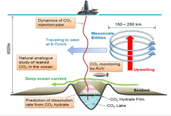
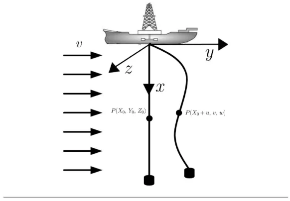
Kyushu University launched CO2 sequestration research as one department in I2CNER (International Institute for Carbon-Neutral Energy Research) in Dec. 2010, sponsored by the Japanese Ministry of Education, Culture, Sports, Science and Technology. The diagram of the research in the ocean CCS division is illustrated in Figure 1.2. The
Figure 1.2: Diagram of the ocean sequestration research at I2CNER
top end of the pipe is connected with a mother vessel while the bottom end is free.
CCS realization, the assessments of environmental impacts are required, such as the dissolution rate prediction from CO2 hydrate which has been studied by Jiang et al. at RIAM (Research Institute for Applied Mechanics) in Kyushu University [3]. Our present research is going to focus on the risks and stability of this cantilevered injection pipe subject to ocean environment.
Dynamic study
According to the author’s knowledge, the dynamics of fluid-conveying pipes in the air at different boundary conditions have been well studied. For a cantilevered pipe discharging fluid in the air, there is a consensus on the stability and two-dimensional (2-D) dynamic analysis is enough. However, there is a contradictions between theory prediction and experimental observation on the stability of a cantilevered pipe aspirating fluid in water.
On the other hand, dynamics of simply-supported marine risers, flexible risers, ocean mining pipes have been well analysed. With the increased focus on offshore oil and gas resources into deeper and harsher environments, internal flow effect has attracted greater attention over the last decades. Dynamic of a cantilevered marine riser with a lower package have been studied motivated by riser retrieval and ocean mining projects, but it remains to be further investigated.
The cantilevered marine riser in ocean CCS is subject to internal flow-induced vibrations (e.g. nutation of the bottom end) and external fluid-induced vibrations (e.g. vortex in- duced vibration). Furthermore, when a marine riser is very long up to thousands of meters, it would behave like a flexible and slender structure, although they are made of rigid materials and the diameters are tens of centimetres. So the riser system would display very rich dynamics inevitably. However, there is almost total absence of theo- retical analysis or experimental investigations of a cantilevered pipe discharging fluid in water except one simple experiment in [4] which tried to investigate the internal flow effect. Therefore, the present research aims to investigate the nonlinear dynamics of a cantilevered pipe discharging fluid in water. And it is expected to design a control sys- tem to reduce or suppress the vibrations in the future, which requires accurate dynamic predictions in advance.
Control system design
Kajiwara et al. [5] targeted the challenging application of an arm-driven inverted pen- dulum. The particular interest of this application lies in the fact that all ingredients of
the design problem have to be taken into account from the specifications up to the con- straints inherent to real-world implementations. They found that a suitable extension of LPV control techniques can overcome the difficulties.
How et al. [6] considered active control of flexible marine riser angle and the reduc- tion of forced vibration by a torque actuator at the upper riser package using boundary control approach. Ge et al. [7] investigated the boundary control of a coupled nonlinear flexible riser to reduce the riser’s vibrations by two torque actuators in the transverse and longitudinal directions. Both of these two control designs were based on partial differential equations of the system derived by Hamilton principle, and thus avoided the drawbacks associated with traditional truncated-model-based design approaches. But according to author’s knowledge, the derived mathematical model can be further refined.
For example, in the hydrodynamic force modelling, the current velocity had better be replaced by relative velocity. The vortex shedding induced forces can be modelled by a more modern technique instead of sinusoidal functions. The coupling of drag force and lift force should be considered at small mass ratiom∗ conditions (m∗ is the ratio of pipe’s mass with inner fluid to the mass of the displaced external fluid).
Stimulated by these control techniques based on partial differential equations, the present dynamic analysis is going to be performed based on mode superposition method which is expected to put foundations for future control system design.
1.3 Outline of this thesis
The paper is structured as follows:
In order to perform accurate dynamic analyses for the pipe system under consideration, we have to develop an accurate mathematical model at first and find the corresponding feasible analysis methods. In Chapter 2, we undertake a great survey of literature to find the influential factors that should be taken into account. The literature review mainly contains two parts. The first part is dynamics of pipes conveying fluid in the air under different boundary conditions. The second part is dynamics of marine risers including rigid marine risers, flexible risers and ocean mining pipes. We should put emphasis on mathematical modelling approaches, effects of system parameters (e.g. internal flow ve- locity, lumped mass(es), nozzle), boundary conditions, external flow effects, instability forms and analysis methods for fluid-conveying pipe systems.
In Chapter 3, we derive the motion equations based on Hamilton principle, taking ac- count of all the essential factors discussed in Chapter 2. We have to find the feasible numerical solution methods based on mode superposition scheme.
In Chapter 4, Simulations are performed based on the derived motion equations and proposed solution methods. The convergence in numerical implementations requires to be confirmed. Comparisons are made between simulation predictions and experiment results to validate the proposed mathematical model and solution methods.
In Chapter 5, we are going to to conduct simulations for parametric investigations.
The effects of an end-mass, internal flow velocity and nozzle-induced tensile force on the dynamics of a cantilevered cylinder system are expected to be examined.
In Chapter 6, conclusions of this research are summarized and works for future study are suggested.
Chapter 2
Literature Review
2.1 Introduction
Dynamics of fluid-conveying pipes in the air and marine risers have been widely studied in literature. However, according to the author’s knowledge, the present research is the first try to investigate the dynamics of a marine riser discharging fluid into the sea. Before going on our investigations, it is of great importance to review literature pertinent to the present study. In this literature review, we are going to finish three tasks. (1) We have to find the feasible mathematical modelling approach (Hamilton principle or Newton method). (2) We should figure out the effects of system parameters (e.g. internal flow velocity, lumped mass(es), nozzle), external parameters, boundary conditions and instability forms of fluid-conveying pipes in order to find the essential factors that should be taken into consideration for mathematical modelling. (3) We should find out the available dynamic analysis methods for fluid-conveying pipes.
2.2 Dynamics of fluid-conveying pipes
Self-excited oscillations of a cantilevered tube in the air at sufficiently high internal flow rate was first recognized by Marcel Brillouin in 1885. Bourri`eres, one of Brillouin’s stu- dents, was first to examine the oscillatory instability of a cantilevered pipe conveying fluid theoretically and experimentally in 1939. Motivated by the study of vibrations of the Trans-Arabian pipeline by Ashley and Haviland in 1950 [8], the stability of a simply- supported fluid-conveying pipe was analysed by Feodos’ev [9] in 1951 and Housner [10]
in 1952 using different approaches. They found that for sufficiently high velocities, the pipe may buckle, essentially like a column subjected to axial loading.
In the past decades, remarkable works on the dynamics of pipe variants conveying fluid (e.g. a plain pipe; pipes with added supports, masses and dashpots along the length of the pipe) at different boundary conditions (e.g. simply supported; pined-pined; clamped- free) have been conducted. These studies have been motivated mainly by two reasons:
(1) The dynamic behaviour of tubes conveying fluid is of considerable importance since oscillations have been observed in various applications such as oil pipelines, moving wires and belts, nuclear reactor components, the Coriolis mass-flow meter, ocean mining and heat exchangers. The fluid-induced vibrations can cause structural failure in some in- cidents resulting in environmental damage and economic loss. (2) A fluid-conveying pipe is of great academic interest and has become a new paradigm in dynamics (i.e.
a new model dynamical problem). This simple system can display a wide variety of the dynamics of more complex engineering problems. The fluid-conveying pipe system has the advantage that one can fairly easily conduct experiments to test the theoretical study [11, 12]. Since extensive historical reviews of this subject have been undertaken in [11, 13–16], this chapter only elaborates on a few of the outstanding previous inves- tigations related to the present study.
2.2.1 Modelling methods and instability forms
Newtonian method
In 1970, Pa¨ıdoussis [17] derived the 2-D motion equations of cantilevered tubes conveying fluid (a hanging cantilever and a standing cantilever) by Newtonian method. It was found that the cantilevers lost stability by oscillatory instability and a standing cantilever might buckle under its own weight. Pa¨ıdoussis and Deksnis [18] investigated the ability of an articulated cantilever to predict a continuous one and found articulated cantilevered pipes may buckle at high modes irrespective of the number of degrees of freedom based on complex frequency calculations. Later in 1974, Pa¨ıdoussis and Issid [13] derived the 2-D motion equations of a pipe conveying fluid at various boundary conditions by Newtonian method and investigated the dynamics and stability. The conservative pipe systems (e.g. clamped-clamped pipes; pinned-pinned pipes) are not only subject to buckling (divergence) at sufficiently high flow velocities, but also to oscillatory instability (flutter) at higher flow velocities. In contrast, the cantilevered pipe was intrinsically a non-conservative system and it lost stability by flutter. The dynamic behaviours of a cantilevered pipe were much more complex and unpredictable than that of a simply- supported pipe.
Hamilton Principle
In 1961, Benjamin [19] investigated the dynamics of a chain of articulated pipes theoret- ically and experimentally. The internal fluid was discharged from the free end of the last articulated pipe. This pioneering work was particularly well known because it formu- lated a modified version of Hamilton’s principle accounting for the energy ∆Wi gained or lost at the bottom end of the last pipe due to the internal flow. After investigations of the energy transfer mechanism, ∆Wi has been proposed as
∆Wi =− Z Tf
0
MiU R˙L
2+UτLR˙L
dt, (2.1)
where U is the internal flow velocity, Mi is the mass of internal fluid per unit length, RL and τL are the position vector and tangent vector at the end of the last pipe, t is the time, Tf is a presumed cycle of oscillation period. A dot denotes a derivative with respect to time which will be used in the following sections.
According to [18], the instability forms of an articulated cantilevered pipe and a con- tinuous cantilevered pipe are different. However, Pa¨ıdoussis [17] proposed the internal induced energy formula for 2-D dynamic study of a continuous pipe system based on equation (2.1) as
∆Wi =−MiU Z Tf
0
h
˙
y2+Uyy˙ 0
L 0
i
dt, (2.2)
where y was the lateral displacement, L was the length of the pipe. A prime denotes a derivative with respect to axial direction which will be used in the following sections.
Equation (2.2) can also be obtained by considering the work done on the tube by the hydrodynamic forces in the course of small periodic motions
dWi dt =−
Z L 0
fi ∂y
∂tdx=− Z L
0
∂y
∂t h
Mi∂
∂t+U ∂
∂x 2
yi
dx, (2.3)
wherefi is the internal flow induced force,xis the axial direction from the top clamped end [17]. If the pipe is simply-supported, y(0, t) = 0 and y(L, t) = 0, then ∆Wi = 0.
For 2-D dynamics of a cantilevered pipe discharging fluid, sincey(0, t) = 0,
∆Wi =−MiU Z Tf
0
˙
yL2 +Uy˙Ly0L
dt. (2.4)
Then the modified Hamilton Principle for a cantilevered pipe discharging fluid from the free end has been proposed as:
Z t1
t
δΨdt= Z t1
t
h M U
∂rL
∂t +UτL
×δrL
i
dt, (2.5)
where Ψ is the Lagrangian of the pipe system. rL and τL respectively represent the position vector and the tangential unit vector at the free end of the pipe.
This modified Hamilton principle equation (2.5) has been employed for 2-D nonlin- ear dynamics of a cantilevered pipe discharging fluid at different bottom end conditions (e.g. with a free end in [20]; attached with an end-mass in [21]; attached with a defected end-mass in [22]). It has also been adopted for 3-D dynamical studies of cantilevered pipe systems discharging fluid with a free end, or in the presence of an end-mass or with an intermediate spring support [12, 23–25]. Notes are made here (1) the cantilevered pipe can be assumed to be inextensible and thus the motion equations can be derived to be of the third order if the lateral deflection is assumed to be small and recorded as the first order. (2) The Hamilton principle for systems of changing mass was derived in a more general way by McIver in 1973 and was applicable to the dynamical analyses of flexible pipes conveying fluid [26]. The modified Hamilton principle expressed as equa- tion (2.5) is just a special case of the Hamilton principle of changing mass.
For dynamic modelling of pipes conveying fluid, Pa¨ıdoussis has demonstrated that mod- ified Hamilton principle and the Newtonian method could yield the very same equation of motion for the sliding end and the cantilevered case, at least to the linear limit [11].
The expression of the linear equation is (E∗ ∂
∂t+E)I∂4η
∂x4 − ∂
∂x h
(T−pAi)∂η
∂x i
+Mi
∂
∂t+U ∂
∂x
η+c∂η
∂t +m∂2η
∂t2 = 0, (2.6) in which,
∂
∂x(T −pAi) =Mi
dU
dt −(Mi+m)g. (2.7)
E∗ is the coefficient of internal dissipation which is assumed to be viscoelastic and of the Kelvin-Voigt type. EI is the flexural rigidity of the pipe. m is the mass of the pipe per unit length. η is the lateral displacement. x andt are the axial coordinate and time. T is the longitudinal tension. pis the inner pressure measured above the ambient pressure.
c is the coefficient of viscous damping due to friction of the pipe with the surrounding stationary fluid medium. Ai is the internal cross-sectional area of the pipe.
(1) There is friction forces between the inner fluid and the pipe. The internal fric- tional force can be expressed asqS, whereq is the wall-shear stress andS is the internal perimeter. The inner fluid pressure p = p(s, t) because of frictional loses, where s is the curvilinear coordinate. The friction force qS can cause a pressure drop in the inner fluid. At the same time, it can increase the tension T. Because of its twin effects, the friction force is absent in equation (2.6) [11].
(2) If the internal fluid is assumed to be constant, gravity, internal damping, exter- nal imposed tension and pressure effects are either absent or neglected, equation (2.7) is translated into
∂
∂x(T −pAi) = 0, (2.8)
then
T −pAi= (T −pAi)|x=L. (2.9)
For a cantilevered pipe discharging fluid in the air, TL = 0 andpL= 0. then equation (2.6) is translated into
EIη0000+MiU2η00+ 2MiUη˙0+ (Mi+m)¨η= 0. (2.10)
Experimental study
The aforementioned energy and Newtonian analytical methods are always combined with experimental validations. For the stability of a fluid-conveying pipe, it is worth- while mentioning that experiments of a tube fixed at the upstream with a knife-edge support movable along the tube were conducted to investigate the general characteris- tics, transition and control of instability in [27]. It was found that the tube lost stability by divergence or flutter depending on the location of the hinged support.
Dynamic analysis of a cantilevered pipe with lumped mass(es)
Referring to the 2-D equation of motion in [28], Hill and Swanson [29] investigated the effects of lumped masses on the stability of fluid conveying cantilevers. The point masses were incorporated in the motion equation itself. This study suggested the possibility that the cantilever can be made considerably more stable by a judicious adding of lumped masses of the correct size and at the proper locations.
In 1992, Copeland and Moon [30] presented experimental studies of a hanging tube with a series of rigid cylindrical end-mass weights attached at the bottom end. With the increase of internal flow velocity, the pipe lost stability from planar oscillations to nutation and chaotic. Between the onset of flutter (a Hopf bifurcation) and chaotic response, there existed a series of increasingly complicated periodic and quasiperiodic motions (e.g. clockwise motion; nutation). Of the nine end-configurations tested, only the fee-end tube moved periodically for the entire flow range. The end-mass can stabilize
or destabilize the pipe depending on the end-mass parameter Γ defined by
Γ = me
(m+Mi)L, (2.11)
wheremeis the end-mass,m and Mi are the masses of the pipe and the inner fluid per unit length,Lis the length of the tube. Anyway, for a cantilevered pipe discharging fluid in the air, it loses the stability from plane oscillation, and thus 2-D analysis is enough from engineering point of view.
In order to extend the work of Copeland and Moon [30], a cantilevered pipe with a mass defect at the free end was investigated in [22]. A cantilevered pipe with a small mass attached at the free end whose motion was constrained to be planar was studied by Pa¨ıdoussis and Semler in [21]. It demonstrated that for the system without end-mass, only one stable periodic solution existed. On the contrary, the dynamics were much richer and different types of periodic solution were found to exist in the presence of a small end-mass.
It should be noted that for a fluid-conveying pipe, the end-mass should be accounted for in the equation of motion via a Dirac delta function rather than in the boundary conditions when the internal flow velocity is not zero referring to [11].
Dynamic analysis of a cantilevered pipe with a nozzle at the free end
In 1966, Gregory and Pa¨ıdoussis [28] derived the motion equations of a cantilevered pipe discharging fluid with a convergent nozzle by Newtonian method. In the 2-D dynamic study, the nozzle was assumed to be weightless and very short compared with the total length of the tubular cantilever. The discharging velocityUj =U Ai/Aj where Aj is the terminal cross sectional area of the nozzle flow passage and a resultant force TL=MiU(Uj−U) is generated which works on the bottom end after considerations of momentum change of the inner fluid at x=L. Then equation (2.9) yields
T−pAi = (T−pAi)|x=L=MiU(U −Uj). (2.12) The linear equation (2.10) becomes
EIη0000+MiU Ujη00+ 2MiUη˙0+ (Mi+m)¨η= 0. (2.13) Therefore, if Uj = 0, the centrifugal force would totality disappear which has been demonstrated by Rinaldi and Pa¨ıdoussis in [31].
Rinaldi and Pa¨ıdoussis [31] examined the dynamics of a cantilevered pipe discharging fluid fitted with a nozzle. The configuration of the nozzle is shown in Figure 2.1. The
Figure 2.1: A plugged end-piece of the 90◦ diverted-flow configuration [31]
nozzle was configured in the way that the straight through path is blocked, so that the flow is discharged radially from a number of holes perpendicular to the pipe. The nozzle was assumed to be an end-mass me and incorporated into the motion equations. The nozzle-induced tensionTL was
TL=MiU(U −0) =MiU2, (2.14) based on momentum change theorem. This nozzle induced tensile force could cancel the centrifugal force and thus stabilize the pipe system dramatically. Equation (2.13) is translated into
EIη0000+ 2MiUη˙0+ (Mi+m)¨η= 0. (2.15)
State of art
Up to now, it gradually becomes a consensus on the stability of fluid-conveying pipes in the air. A simply-supported pipe loses stability by divergence (i.e. buckle) at sufficiently high flow velocity. A cantilevered pipe loses stability by planar flutter. A cantilevered pipe discharging fluid in the air, being an inherently non-conservative system, is capable of displaying a seemingly inexhaustible variety of interesting and often surprising be- haviours, compared with a pipe with both ends supported. 2-D theory is sufficient for predicting the buckling (static divergence) of a simply-supported pipe, or the dynamic instability of a cantilevered one, since these are physically bifurcations [12]. Driven by
curiosity, 3-D dynamics of cantilevered pipes (one is constrained by intermediate non- linear springs and the other is fixed with a bottom end-mass) were analysed based on modified Hamilton principle in [12, 23–25].
2.2.2 Analysis methods
Mode functions
In order to discretize the motion equations, researchers have to employ proper mode functions as the comparison functions. They often employ the mode functions of a beam which satisfied the same boundary conditions as the base functions. Specifically speaking, for the 2-D or 3-D, linear or nonlinear equations of a fluid-conveying can- tilevered pipe, horizontal (the gravity effects are either absent or negligible) or vertical, with/without lumped masses, constrained or unconstrained, it is feasible to utilize the orthonormal eigenfunctions of a cantilever rather than eigenfunctions from the linear equations of motion in which the effect of the lumped mass, gravity and partly the flow velocity as the comparison functions, referring to [12, 13, 17, 21–25, 29, 31, 32].
Not using enough modes can lead to unreliable and even erroneous results [24]. For relatively low flow velocities, 2-4 modes are sufficient to obtain reliable results [12] in 2-D study. 6 modes in each direction are enough in the 3-D dynamical investigations of cantilevered pipes [24]. It is noted that the adopted mode numberN = 6 in [29],N = 4 in [22],N = 5 in [31]. In order to capture the dynamics of a vertically hanging long pipe with modal analysis, high enough modes with short enough wavelength must be con- sidered. Sometimes many Galerkin modes are needed to obtain convergent results and may put the calculations beyond out current computational capabilities. An alternative approach to overcome this problem could be to use other comparison functions when discretizing the nonlinear partial differential equations by Galerkins technique [24].
Stability based on linear motion equations
Stability depends on the nature of the roots of a certain determined equation [19]. The solution of derived dimensionless linear motion equations can be assumed to be
η(ξ, τ) =φ(ξ)eiωτ, (2.16) whereφ(ξ) can be expressed by superposition of adopted proper comparison functions.
ω is the dimensionless complex frequency and the real component Re(ω), represents the oscillation frequency of the system, while the imaginary part Im(ω), is related to the
damping of the system. The pipe system will be stable or unstable according to whether Im(ω) is positive or negative. Positive values of Im(ω) give rise to damped oscillations while negative values of Im(ω) result in amplified oscillations. In the case of neutral stability, ω is wholly real. The Argand diagram can be depicted and thus the stability of the pipe system can be determined (e.g. [31]). Auto, a program for the automatic bifurcation analysis of autonomous systems was developed in [33].
Solution methods of nonlinear motion equations
The 2-D nonlinear motion equations of a cantilevered pipe discharging fluid were de- rived based on modified Hamilton principle which accounted for nonlinear terms up to the third order, assuming the lateral displacement was small and recorded as the first order [20]. Referring to [20], the 2-D nonlinear motions of a cantilevered pipe with a mass defect at the free end was derived. The solutions to the derived nonlinear motion equations were obtained principally by a fourth-order Runge-Kutta integration algo- rithm with a time step size of 0.001 s. Auto was used in order to find unstable limit cycles in [22].
Motivated by the nonlinear dynamical investigations of cantilevered pipes conveying fluid, in order to deal with the difficulties encountered in achieving convergent solutions to the nonlinear motion equations with large nonlinearities (especially when there was a large inertial nonlinearities), three specific numerical schemes was examined by Semler et al. in [34]. It has been found that the Incremental Harmonic Balance (IHB) method can yield accurate periodic solutions, together with the frequency of oscillation, and the dynamical stability of the system might be assessed very easily. Both Houbolt’s and the eighth order scheme can be used to compute time histories of initial value problems if the time step is properly chosen, although the Houbolt’s scheme may induce phase shift in the time trace. Employing the Finite Difference Method and IHB, the 2-D dynamics of a cantilevered pipe with an end-mass was analysed without assuming the end-mass or nonlinear inertial terms were small in [21]. For 3-D nonlinear dynamics of cantilevered pipes, the motion equations were solved by Houbolt’s finite difference scheme and Newton-Raphason method in [23–25].
2.3 Dynamics of a cantilevered pipe aspirating fluid
Three unresolved or partly resolved issues in fluid structural interactions (FSI) were discussed in [35]. One of the unanswered problem is the contradiction between theo-
aspirating fluid at their free end and conveying it toward the clamped end. Theoretical work based on the energy method in equation (2.4) shows that cantilevered pipes loses stability by flutter at infinitesimally small flow velocities. However, aspirating pipes appear to remain stable to at least high flow rate. This problem is related to Feynman’s aspirating rotary-sprinkler quandary and this paradox is of importance not only in terms of fundamentals, but also in practical engineering terms, namely, in the field of Ocean Mining [36]. Recently, a new concept has been developed of liquefying natural gas on a barge offshore and this process requires large volumes of cooling water [37]. Designs have been made for pipes suspended from a floating barge, which will be used for pumping up cooling water [38].
Researchers have been trying to explain the contradiction through negative pressuri- sation of water at the inlet of the pipe in [39], and the hydrodynamic drag caused by surrounding water in [38]. Kuiper et al. [37] made a realistic description of hydrodynamic drag in combination with conventional boundary conditions (i.e. the fluid momentum remains unchanged as the fluid enters the pipe) or new descriptions of the boundary conditions. It found that the predicted critical velocity were both much higher than that attainable in small-scale experiments and concluded that the correct description of the flow field in the vicinity of the tip and the external hydrodynamic drag would be of great importance for the prediction of the stability of the pipe system.
An experiment of a partly submerged cantilever pipe aspirating water was conducted in one test set-up in which the fluid velocity through the pipe could exceed all predicted critical velocities by the present theories [40]. Statements have been made based on this experiment study:
(1) Existing theories can predict the dominant frequencies quite well. However, they do not correctly predict the critical velocity and the pipe behaviour in the unstable regime.
(2) Below the critical velocity, the system is stable, whereas above it the system shows a complex motion that consists of two alternating phases: nearly periodic orbital mo- tion and noise-like vibration with very small amplitudes. No planar motion has been observed.
(3) Increasing the internal fluid velocity results in an increasing amplitude of the or- bital pipe motion, but does not change the pipe motion qualitatively.
(4) It seems that the flow field in the vicinity of the tip is of great importance for
the correction prediction of the dynamic behaviour of the cantilever pipe conveying fluid.
Recently, Giacobbi et al. [41] explored this problem in three ways: experimentally, numerically and analytically. A fully coupled coupled Computational Fluid Dynamics (CFD) and Computational Structural Mechanics (CSM) model was developed in ANSYS for numerical simulations. The linear equations were derived by a Newtonian analyt- ical approach and solved via the Galerkin method in order to determine its stability characteristics.
2.4 Dynamics of marine risers
Offshore platforms can broadly categorized in two types. One type is the fixed struc- tures that extend to the Seabed (e.g. Steel Jacket). The other type is recently developed structures that float near the water surface (e.g. Semi Submersible).
Risers are pipes used for production, drilling, and export of oil and gas from seabed.
The riser connects a subsea well-head or other equipment located at the sea floor to the platform at the surface. Risers can be classified into drilling risers and production risers.
The production risers are also classified into rigid riser and flexible riser. Flexible risers are widely deployed for hydrocarbon production or water injection with conventionally moored floating platforms (e.g. FPSO; semi-submersibles ) [42].
Moorings and anchors are used to tie platform in place. Moorings can be classified into three types by material: steel chain, steel wire rope and synthetic fiber rope.
2.4.1 Dynamic analysis of rigid risers
The essential features of drilling risers design were defined by static analysis employing the series solution method in [43]. The significance of dynamic behaviour for riser design was recognized by national Engineering and Science Co. (NESCO) in their analysis of the 14,000-ft-long drilling riser for Project Mohole. Burke [44] analysed statically and dynamically a 16-in. riser in water depths from 400 to 2,000 ft employing a numerical integration scheme by finite difference methods (FEM) and concluded that the dynamic response of the riser was a significant factor in design for all water depth, at least beyond 400 ft. Static analysis was then superseded by a more advanced dynamic analysis with the advent of the modern computer.
A rigid marine riser have always been modelled as a tensioned beam. The dynamic re- sponse calculations were usually based on FEM or Finite difference method (FDM) and numerous riser computer programs had been developed in both time and frequency do- mains. In 1979, Kirk et al. [45] presented a frequency domain normal mode solution for the dynamic response of an unbuoyed marine riser. The variable tension beam-column equation was solved in terms of normal modes of free vibration of the riser and the rigid body displacement. Dareing and Huang [46] were the first to propose the possibility of the modal analysis method in time domain and achieved an acceptable convergence and engineering accuracy. The vibration modes and corresponding natural periods were determined from the closed form solutions from finite difference representation of the undamped free vibrations differential equation. In 1982, Chakrabarti and Frampton [47]
made a comprehensive overview and illustrated how the earlier static analysis progressed to the more sophisticated and complex dynamic analyses. Up to that time, none of the papers had included the effect of the lift force in the stress analysis of the riser and only the internal flow induced static hydrostatic pressures had been taken into account for the internal flow effect.
Exploration for oil and gas has been progressing into deeper water. The design and analysis of risers in deep water require more careful considerations. Parametric study have been performed widely to investigate the influential system parameters and exter- nal excitations.
Internal flow effect has attracted greater attention since severe vibrations of the Trans- Arabian pipeline were observed in 1950. The paper on internal flow effect was fist published by Moe and Chucheepsakul in [48]. Wu and Lou [49] developed a mathemat- ical model for the lateral motion of a marine riser to examine the effect of the internal flow and bending rigidity of the pipe at high top tension by a singular perturbation tech- nique. It was found that the internal flow acts to reduce the effect of the top tension.
The internal flow effect was not significant when the top tension was relatively high.
However, the perturbation technique was not valid at small top tension cases.
In 1997, Atadan et al. [50] derived the mathematical model of a production riser un- dergoing 3-D deflections and rotations in the presence of ocean waves and currents by Lagrangian formulation, in which the platform was assumed to be a point mass. The 3-D motion equations were simplified to 2-D equations to investigated the effects of certain parameters including flexural rigidity, length, tip mass, current and waves. It assumed the nonlinearities were small and the solutions were obtained using Butenin’s method.
In 2005, Kaewunruen et al. [51] derived the nonlinear motion equations coupled in axial
and transverse displacements based on Hamilton’s principle. They investigated the non- linear free vibrations of marine risers to determine the nonlinear natural frequencies and the corresponding mode shapes. The nonlinear effects of flexural rigidity, top tension, internal flow velocity and static offset were investigated.
The partial differential equation of marine structures (e.g. tension leg platform tethers) subject to the harmonic excitations exerted on the top end of the system can be reduced the nonlinear Mathieu equation and solved by numerical methods [52–54]. Patel and Park [52] reported on the first stage of an investigation into the dynamics of tethers with reduced pretension to facilitate payload increase over conventional design of a TLP. The time-varying axial force caused the tether to undergo parametric oscillations described by the Mathieu equation and the Mathieu stability chart was obtained over a wide range of parameters. Patel and Park [53] presented the results of an investigation into the combined axial and lateral vibrations of the tethers of tensioned buoyant platforms by Mathieu stability chart. Park and Jung [54] presented a numerical analysis of lateral responses of a long slender marine structure under combined parametric and forcing excitations by Mathieu stability chart.
2.4.2 Dynamic analysis of flexible risers and cables
For conventional tensioned steel risers, 5% to 9% of water depth being topical maximum offsets that such risers can tolerate are the operating constrains. These tight offset limits impose strict design criteria on the vessel mooring systems. A flexible riser of catenary configuration offers an alternative solution which allows substantial greater vessel offsets from the well head, as well as eliminating the need for a heave compensator/tensioner device [55]. Recently, the need for deeper drilling led to the use of very long risers made from light and flexible materials. Flexible risers have been qualified to 1500 m and are expected to be installed in depths of up to 3000 m in the next few years [56].
The modelling and analysis of flexible risers have been well undertaken in the past decades. Patel and Sey [57] presented an historical overview of the development of hy- drodynamic analysis techniques for flexible risers including static analysis, frequency domain dynamic analysis and time domain dynamic analysis. The classical catenary equations can provide a good approximation for static analysis. The catenary solution are simply in concept and are extremely fast and reliable. However, it requires refine- ments for an adequate static analysis especially when the offset angle is larger than 10◦. The static analysis equations can be readily be extended to a dynamic form [55].
Patel and Seyed [55] stated the internal flow could exert three kinds of forces on the struc- ture: (1) Hydrostatic pressure; (2) Steady and time-dependent forces due to momentum changes; (3) Coriolis force. They derived the 2-D differential equations describing the static behaviour of a flexible riser of arbitrary geometry taking account of (1) and (2).
Sey and Patel [58] presented the derivation for calculation of pressure and internal flow induced forces on flexible risers using a mathematically rigorous approach. The derived governing equations were reduced for specific cases of simple caternary, steep-S, lazy-S, steep-wave and lazy-wave risers.
Patel and Sey [57] summarized the important factors that had been neglected in the flexible riser modelling which included structural damping, tangential hydrodynamic drag load, seabed interaction effects, vortex shedding and out of plan oscillations of midwater buoys. It has been argued that a full 3-D time-domain analysis should be used for flexible riser analysis. In 1989, O’Brien and McNamara [59] outlined a full 3-D solution for general flexible pipelines and riser configurations based a hybrid beam- column finite element. Full 3-D time-domain dynamic analyses with inclusion of pressure and slug flow effects were developed at University College London with the support of a joint industry-funded research programme [55]. However, up to now, this work was never published because it was carried out for an oil company that wanted it kept con- fidential (by private communications with prof. Patel).
Analyses of flexible risers are always accompanied by those of other offshore marine slender structures. Dynamics of mooring systems and cable systems have been well studied referring to [60].
Triantafyllou et al. derived the motion equations of a cable system and performed linear and nonlinear dynamical study [61–64]. The derived motion equations have been widely employed afterwards for slender marine structures. Note that Triantafyllou pre- ferred the local tangential, normal, binormal directions because of certain advantages it offers, most notably the decomposition into transverse and longitudinal waves, which is natural to this system and the relative ease of determining the fluid drag force. Some disadvantages exist, because it is a non-inertial system, and hence a fixed Cartesian system may have advantages for certain applications [60]. When a cable moves with large amplitude motion, or in the presence of an ocean current, vortices form causing substantial unsteady forces, which lead to vortex-induced vibrations. As a result of vor- tex induced vibration (VIV), the drag coefficient may be amplified by a factor often in excess of 3 [60]. Peyrot and Goulois [65] developed a numerical procedure to examine complex 3-D assemblies of substructures and cables taking account of the lift force due to vortex shedding for static analyses. When the tension is small, cables and chains lose
their principal stiffness mechanism, and the governing equation become ill-posed. Hence, an explosive instability dominated the response and no convergent numerical solution can be found. By including a small bending stiffness term we correct the problem of ill-posedness [60].
According to the author’ survey, a comprehensive model which has got the general consent of the society does not exist. Dynamical investigations of flexible marine risers at parametric and forcing excitations have been performed employing different mod- els with adopted solution methods by Chatjigeorgiou et al. [56, 66–70]. For example, Chatjigeorgiou et al. [68] derived the motion equations for vertical marine risers taking account of internal flow effect which contained terms up to the fourth order. The differ- ential equations were solved discretized by a Galerkin approximation and solved by the Newmark’s numerical integration scheme in the time domain for risers at various types of supports. They found that the marine structural was subject to several nonlinear instabilities, which were caused primarily due to the velocity of the internal flow and the parametric excitation. Chatjigeorgiou [69] employed the cable model derived by Triantafyllou and performed dynamical investigations under parametric excitation by two different numerical schemes (i.e. Finite different approximatin scheme and Modal expansion solution method). The effect damping was examined end the significance of the terms that described the coupling between the longitudinal and transverse vibrations was demonstrated. Employing the cable equations derived by Triantafyllou, [70] pro- posed a finite differences solution method based on Box approximation for the numerical treatment of the dynamic equilibrium problem of 2D caternary risers. The convergence was confirmed and the effect of the geometric nonlinearities was assessed.
2.4.3 Dynamic analysis of a deep ocean mining pipe system
In the configuration of a deep-ocean mining system, the top end of the pipe is pinned to a ship’s moonpool and the bottom end is connected to equipment on the sea floor.
The bottom end of a deep ocean mining pipe system
In order to aid the design of a mining system, the design of a position-control operation system for the mining system, and also required by control operation simulations of the mining system, the pipe bottom was simulated in time domain by Chung et al. in [71]. The pipe was modelled by 3-D beam finite elements which account for coupled axial, bending and torsional deformations. The governing equations were solved by an
implicit-time-integration method which allowed for the use of large step sizes (time step sizedt= 2.0 s was used without reducing the numerical accuracy).
The stretching oscillation of a deep ocean mining pipe system
The pipe’s stretching oscillation would be initiated by vertical components of the plat- form or ship motion, or coupling with internal flow [72]. The axial motion of a mining pipe was decoupled from the lateral motion and the vertical stretching oscillation was analysed by Chung and Whitney in [72]. They found that the vertical oscillatory buffer displacement could pose serious problem during deployment, and retrieval operations of the mining system, particularly during the touch-down and take-off of the miner or col- lector on the seafloor. Later, the measurements of a 5000-m-long, 15-in outer-diameter mining pipe showed that the pipe bottom undergoes dynamic stretching at axial reso- nance in addition to its static stretch. The axial stress can be an order of magnitude larger than the bending stress for such a long pipe, and the bending was less of an issue which changed the common perception [73].
An automatic position control of a deep ocean mining pipe system
The combined ship-pipe-buffer system must be positioned in such a way that the buffer position be maintained close to the miner during station-keeping and mining operation.
The feasibility of an automatic position control of a 300,000 tons ship during ocean mining operations was demonstrated by Brink and Chung in [74]. Passive buffer con- trol and active buffer control were discussed based on extensive simulation study and performance analysis.
VIV effect of a deep ocean mining pipe system
Lateral vibrational displacements and accelerations due to vortex shedding were analysed for very long marine pipes with a bottom end mass for ocean-mining application in [75].
The cross-flow (CF) displacement was expanded in terms of the normal modes which were calculated using a finite element computer code. The effect of pipe length, pipe diameter and buffer weight on the root-mean-square (RMS) CF displacements were analysed. In order to devise a vortex-suppression technique, five basic configurations of vortex-suppression devices were investigated experimentally in [76, 77]. They found that two configurations (i.e. a pipe straked with electro-mechanical power cables arranged in helical form with a pitch angle of 58◦; a pipe with a perforated shroud) were the most effective to reduce vortex-shedding intensity.
3-D study of a deep ocean mining pipe system
3-D nonlinear, coupled axial, bending and torsional responses of vertical ocean-mining pipe systems conveying slurry flows upward were well analysed by nonlinear FEM [78, 79]. in [78], the bottom end, connected to the seafloor equipment, was allowed to move axially and rotated about the pipe, but was restrained against the lateral dis- placements. In [79], the bottom end was attached with equipment and was free and independent of the self-propelled seafloor nodule miner. The torsional moment on the buffer and the estimated nodal torsional moments were also discussed in [79]. The re- sponse characteristics in [79] were quite different in many aspects from that in [78]. For the internal flow effect, axial or tangential shear force due to the wall friction from the solid-water slurry flows was taken into account and the effect was found to be not so obvious in [78, 79].
2.4.4 Dynamic analysis of a cantilevered marine riser
A hanging string
Dynamic and stability of a hanging string in fluid subject to parametrically excitations have been well studied referring to [80–83]. It is worthwhile noting that the paradox of a hanging flexible string can be solved by introducing a small bending stiffness [82].
Dynamics of a cantilevered marine riser or a cable with rigidity
In offshore activities, there are many applications of free hanging marine pipes such as ocean thermal energy conversion pipes, deep-sea water exploration pipes, oil exploration and production risers during retrieval conditions [84]. When a riser is free hanging in the retrieval process, the provision of hydraulic and mechanical disconnect and reconnect equipment adds a significant amount of mass to a lower marine riser package. Thus, when unlatched, the marine riser is analogous to a very long submerged pendulum with the lower riser package acting as a concentrated mass and the riser pipe behaving like a long slender string [85].
Dynamics of a free hanging riser exposed to the excitations of the floating vessel, wave, or current was analysed using FEM and scaled model tests were carried out in [85]. A Lissajous figure shaped orbit motion was observed while the out-of-plane motion due to vortex shedding effects remained to be examined.
Park, Jung and Koterayama have presented a numerical and experimental investiga- tion on dynamic behaviours of a cable [86, 87] and a highly flexible free hanging pipe subject to top end excitations [84, 88]. The 3-D dimensional cable equations were em- ployed to modal the cable and pipe considering fluid and geometric nonlinearity. Bending stiffness was considered to cope with the low tension problem. The equations could be solved by an implicit finite difference algorithm with Newton-Raphson iteration and a 3-D numerical solution program was developed. In the cable study by Park et al. in [86, 87], good agreements was achieved between numerical predictions and experimental measurements only when the normal and tangential coefficients were adjusted by con- sideration VIV effect. The increased drag coefficient have been calibrated as a function of CF amplitudes. But it is very difficult to measure the amplitude in CF displacement for a towed cable, so the drag coefficient was thus increased in the ratio of the tension fluctuation amplitude and assumed to be a constant at a fixed towing speed. There were still differences in some cases due to effect of cortex shedding on the drag coefficients [86]. In the experiment of a free-hanging pipe by Park et al. [88], the largest cross-flow vibrations occurred at the bottom part of the model for all excitation frequencies and amplitudes. Transverse structural wave propagation was also observed. In the numerical study, the drag and inertial coefficients were taken as 1.5. Drag coefficient variation due to vortex shedding was not considered because of structural random vibrations. Only the in-line (IL) displacements were compared between numerical and experimental re- sults. Good agreements were observed in upper and mid parts of the pipe, but there are some differences in the bottom part due to the large interaction between IL motion and VIV induced CF motion which was the largest at the bottom part [84]. In the case of slender marine structures with free end at bottom, the dynamic behaviour of the bottom part was very important to safety operation [84], a further research taking account of VIV effect remains to be carried out.
Internal flow effect on a cantilevered pipe discharging fluid
It is of great significance to review the experiment in [4]. It experiment employed a cantilevered immersed pipe discharging fluid subject to forced excitation at the top end.
It was found that internal flow rate significantly lowered the natural frequency of the system. In cases where one of the natural frequencies (containing fluid but no velocity) was slightly above the forcing frequency, the natural frequency was lowered to the nat- ural frequency and thus producing a corresponding mean response intensity as the flow rate was increased. It concluded that the differences in response amplitudes of 30 to 100 percent, caused by an increasing or decreasing internal flow rate can have far reaching effects on system stability and fatigue.