INVITED PAPER
Special Section on Electronic DisplaysMulti-Phase Convex Lens Array for Directional Backlights to Improve Luminance Distribution of Autostereoscopic Display
Shuta ISHIZUKA†a), Takuya MUKAI†,andHideki KAKEYA†,Nonmembers
SUMMARY We realize homogenous luminance of the directional backlight for the time-division multiplexing autostereoscopic display using a convex lens array with the elemental lenses whose phase of placement in each row differs from one another. The validity of the proposed optical design is confirmed by a prototype system.
key words: autostereoscopic display, homogeneous brightness, liner Fres- nel lens array
1. Introduction
With the recent advances of LCD technologies, LCD panels that attain short response time have been developed, which has enabled commercialization of 3D LCD TV sets. The ad- vanced LCD technologies with high refresh rates can also be applied to autostereoscopic displays with high resolutions.
Most of the conventional autostereoscopic display sys- tems are based either on parallax barrier technology or on lenticular lens technology, both of which display stereo- scopic images with lower resolutions than those of the dis- play panels. Time-division multiplexing technique with a fast response panel has enabled presentation of a stereo- scopic image with the same resolution as that of the display panel.
The conventional ways to attain high resolution au- tostereoscopy with time division multiplexing are roughly divided into two types.
One way is to use an active parallax barrier[1]–[3]. A fixed parallax barrier generating two viewpoints reduces the resolution of the image by half. This problem is avoided by turning on the odd columns and the even columns of the striped barrier alternately. When the alternation of the par- allax barrier is synchronized with that of the image on the display panel, the viewer is able to observe a full resolution 3D image.
The other way is to use a directional backlight com- posed of a light guide film and two light sources[4]–[6].
In this system autostereoscopy is realized by switching the light sources and the image on the display panel syn- chronously.
The common drawback of the autostereoscopic dis- plays introduced so far is the limited number of viewers.
Basically they can display the stereoscopic image only to Manuscript received February 28, 2015.
Manuscript revised June 4, 2015.
†The authors are with University of Tsukuba, Tsukuba-shi, 305–8573 Japan.
a) E-mail: [email protected] DOI: 10.1587/transele.E98.C.1023
one viewer. Though there have been a few trials to increase the number of possible viewers[7],[8], the viewing position is still limited.
One way to attain autostereoscopy with more view- points is to use a directional backlight composed of a large aperture convex lens and a dot-matrix backlight panel[10].
The same optics is also attained by using a concave mir- ror[11]. These systems, however, require deep optical dis- tance.
To reduce the thickness of the display hardware, use of a convex lens array instead of a large aperture convex lens was proposed[12]–[15]. The image quality attained by this system, however, is poor due to the distinct seam of the lens array, which has prevented this method from being put to practical use. Though use of a vertical diffuser combined with a lens array and projection light[16], [17] mitigates the problem of distinct lens seam, the system becomes thick again due to the projection optics.
Ishizuka et al. proposed a method to solve the above problem without projection optics[18]. The proposed sys- tem uses a hexagonal lens array in place of the conventional lens array, accompanied by a vertical diffuser behind the dis- play panel, which blurs the distinct seam of the lens without destroying stereoscopy. In this system projection light is not necessary because the optical parameters are set so that the optical aberration may not cause the overlap of the backlight areas for the left eye and the right eye[19].
Use of a vertical diffuser, however, does not eliminate the lens seam completely due to the periodical lens align- ment. Though this problem is partially solved by tilting the hexagonal lens array, slanted stripe noise still appears es- pecially when the viewer observes the image from a wide angle.
In this paper, we propose a new method to realize the uniformity of the directional backlight for autostereoscopic displays. This paper is organized as follows. The con- ventional method is reviewed in Sect. 2 and the proposed method is explained in Sect. 3. The result of the hardware experiment is given in Sect. 4 and the paper is concluded is Sect. 5.
2. Conventional Method
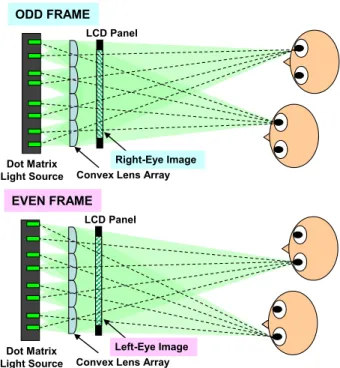
The principle of the conventional directional backlight using a convex lens array is shown in Fig. 1. When dot matrix light sources are placed behind the convex lens array so that the distance between them may be equal to the focal distance of Copyright c2015 The Institute of Electronics, Information and Communication Engineers
Fig. 1 Autostereoscopy with a directional backlight using a convex lens array
the elemental lens of lens array, collimated directional light is realized. By changing the position of the luminous light sources, the directionality of light is controlled. When the directional backlight to each eye alternates synchronously with the alternation of left-eye and right-eye images on the LCD panel, the viewer can see a stereoscopic image with- out wearing special glasses. By increasing the number of light sources, multiple viewers can observe the stereoscopic image simultaneously.
The problem of the conventional system shown in Fig. 1 is poor image quality due to the distinct seam of coarse lens array. Also the intensity of image is not uni- form because the intensity of light rays generally weakens as the angles become wider, which causes emergence of bright area and dark area in each elemental lens. To remove the seam of lens and the non-uniformity of intensity from the image, two methods have been proposed so far.
The first method is to use a hexagonal lens array and a vertical diffuser as shown in Fig. 2. The hexagonal lens ar- ray is used because it has two complementary phases, which avoids concentration of bright area and dark area in each vertical line. The diffuser is inserted to blur the seam and non-uniform intensity of lens array. To maintain autostere- oscopy, the rays into the left eye and the right eye of the viewer should be separated. The ray diffused only in the vertical direction maintains directionality of light in the hor- izontal direction, which does not destroy stereopsis. Though this method homogenizes intensity to a certain degree, dark and bright stripes remain.
The second method is to tilt the convex lens array in the first method as shown in Fig. 3. Though the vertical stripes disappear with this method, slanted stripes become distinct
Fig. 2 Autostereoscopy with a directional backlight using a convex lens array and a vertical diffuser.
Fig. 3 Autostereoscopy with a directional backlight using a tilted convex lens array and a vertical diffuser.
Fig. 4 The blur effect of the vertical diffuser observed from different an- gles.
especially when the viewer observes the image from a wide angle
The reason of the emergence of stripes is explained as follows. Figure 4 shows how a white square light looks af- ter diffusion with the vertical diffuser. The left picture shows how the diffused square looks from right in front of the dis- play and the right picture shows how it looks from a side an- gle of the display. When the position of light is right in front of the observer, a straight vertical line is observed. When the observer moves sideways, the line is curved in a bow shape.
The slanted stripes are generated because of this curved dif- fusion. When the inclination of the curved diffusion matches the inclination of the tilted lens array, the bright part and the dark part of the elemental lenses are not mixed, which re- sults in the emergence of stripes.
Fig. 5 The proposed alignment of elemental lenses.
3. Proposed Method
In this paper we propose a method to attain homogenous image intensity from any viewing angle. The feature of the proposed system is the alignment of the elemental lenses.
In the proposed method the elemental lenses are aligned so that the phase of lens placement in each row may differ from one another as shown in Fig. 5. Since the seam of the lenses appear only once in the vertical direction, the vertical dif- fuser can smooth the seam enough and the image with ho- mogeneous intensity can be attained. Also because of the various phase shift, inclination angle of the phase shift is not uniform, which can avoid a singular match between the inclination of the diffusion curve and that of the lens shift.
Here note that the position of the bright part of the backlight should be shifted in accordance with the shift of the lens to maintain proper directional light for stereoscopy.
To realize the image intensity as homogenous as pos- sible, the order of phase shift is important. To avoid reg- ularity of inclination, we align the lenses as follows. Here we explain the case where the number of rows is 30. 30 is decomposed into prime factors 2, 3, and 5. Note that 360/2 = 180 and 360/3 = 120. First, two lenses with 180 degree phase shift are placed next to each other. Then three pairs with 120 degree phase shift or−120 (240) de- gree phase shift are placed next to one another. Mixing 120 degree and−120 degree phase shift is important to remove periodicity only in one direction. Finally five groups of six lenses are placed with−144 (216) or 156 degree phase shift alternately again to remove periodicity. 156 (= 180−24) and−144 (=−180+36) degrees are selected so that every row may have a different phase. This alignment contributes to suppress emergence of bright and dark stripes when the viewer observes the image from a wide angle.
To mix the bright part and the dark part enough, it is favorable to use the elemental lenses short in height, which in turn allows intrusion of the backlight for the neighboring elemental lenses To avoid it, we place mirrors between the backlight and the elemental lenses so that each row of the elemental lenses are separated from one another.
4. Result
We made a prototype system based on the proposed method
Fig. 6 Prototype system.
described in the previous section as shown in Fig. 6. As the LCD panels for the image display panel and the dot- matrix backlight, we used a pair of BenQ XL2420T, which can show 24 inch full HD images with 120 Hz refresh rate.
As for the vertical diffuser we used a fine lenticular lens with 0.1 mm pitch and 0.05 mm radius, which was placed just behind the front image panel and 150 mm in front of the convex lens array. As for the convex lens array we used a 43.8 mm (W)×10 mm (H) linear Fresnel lenses whose fo- cal length was 45 mm. Here linear (cylindrical) lenses can be used in place of standard convex lenses because the direc- tionality of light only in the horizontal direction matters to realize stereoscopy. Note that the partition (mirror) to sep- arate each lens row is essential when linear lenses are used, for the light is not converged in the vertical direction.
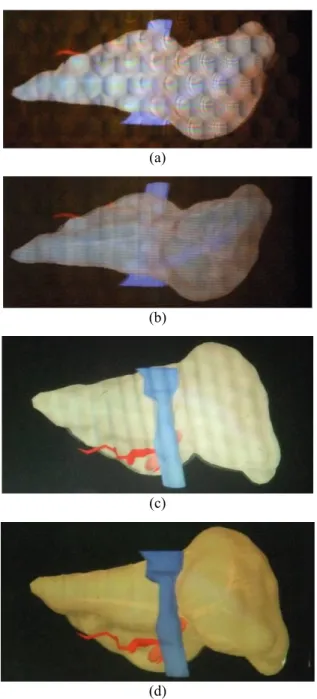
In Fig. 7 we compare the images presented by the con- ventional methods and the proposed method. In the con- ventional systems regular hexagonal elemental lenses that have 25 mm focal length and 12.5 mm sides accompanied by the same LCD panels as those of the proposed system were used. The image given by the system shown in Fig. 1 in- cludes distinct seams of lenses and the image quality is poor (Fig. 7 (a)). After insertion of a vertical diffuser, the image becomes more uniform, while the vertical seam is still no- ticeable (Fig. 7 (b)). After tilting the lens array, the oblique periodical noise stands out (Fig. 7 (c)). As opposed to these conventional systems, our proposed method realizes an im- age without any apparent seam or stripe noise (Fig. 7 (d)).
Thus the validity of the proposed method is confirmed.
5. Conclusion
In this paper we propose the new alignment of the convex lens array where the phase of lens placement in each row may differ from one another to realize homogenous inten- sity of the directional backlight. In the proposed system the forward and the backward phase shifts are mixed so that the seam of the lenses may not concentrate in any inclination angle. It is confirmed with the prototype system that the
Fig. 7 Comparison of the images presented by the conventional methods (hexagonal lens array without vertical diffusion (a), hexagonal lens array with vertical diffusion (b), inclined hexagonal lens array with vertical dif- fusion (c)) and the proposed method (d).
proposed method successfully removes the stripe noises as expected.
Acknowledgements
This research is partially supported by the Grant-in-Aid for Scientific Research, JSPS, Japan, Grant number: 25280070.
References
[1] K. Perlin, S. Paxia, and J.S. Kollin, “An autostereoscopic display,”
Computer Graphics, pp.319–326, 2000.
[2] H.J. Lee, H. Nam, J.D. Lee, H.W. Jang, M.S. Song, B.S. Kim, J.S.
no.1, pp.215–217, 2010.
[6] M.J. Sykora, “Optical characterization of autostereoscopic 3D dis- plays,” SPIE Proc. 7863-29, 2011.
[7] C.-H. Ting, C.-Y. Hsu, C.-H. Yang, Y.-P. Huang, H.-W. Tsai, and C.-C. Yu, “Multi-user 3D film on directionalsequential backlight system,” SID11 Digest, vol.42, no.1, pp.460–463, 2011.
[8] H. Kwon and H.-J. Choi, “A time-sequential multi-view autostereo- scopic display without resolution loss using a multi-directional backlight unit and an LCD panel,” Proc. SPIE 8288, 82881Y, 2012.
[9] Y.-P. Huang, et al., “Development of time-multiplexed backlight on auto-stereoscopic LCD for multi-user and wide-viewing angle func- tion,” Proc. IDW/AD ’12, pp.1889–1892, 2012.
[10] T. Hattori, T. Ishigaki, K. Shimamoto, A. Sawaki, T. Ishiguchi, H.
Kobayashi, J.O. Merritt, M.T. Bolas, and S.S. Fisher, “Advanced autostereoscopic display for G-7 pilot project,” SPIE Proc. 3639, pp.66–75, 1999.
[11] A. Hayashi, T. Kometani, A. Sakai, and H. Ito, “A 23-in. full-pan- el-resolution autostereoscopic LCD with a novel directional back- light system,” Journal of the Society for Information Display, vol.18, no.7, pp.507–512, 2010.
[12] T. Hattori, “Stereoscopic Picture Display Device,” JP Patent 08- 160355, A, 1996.
[13] T. Hattori, “Stereoscopic Picture Display Device,” JP Patent 08- 160356, A, 1996.
[14] T. Hattori, “Stereoscopic Video Display Device,” JP Patent 08- 160556, A, 1996.
[15] T. Hattori, “Stereoscopic Video Display Device,” JP Patent 08- 163603, A, 1996.
[16] P. Surman, I. Sexton, K. Hopf, W.K. Lee, F. Neumann, E.
Buckley, G. Jones, A. Corbett, R. Bates, and S. Talukdar, “Laser- based multi-user 3-D display,” J. Soc. Inf. Disp., vol.16, no.7, pp.743–753, 2008.
[17] D. Miyazaki, Y. Hashimoto, T. Toyota, K. Okoda, T. Okuyama, T.
Ohtsuki, A. Nishimura, and H. Yoshida, “Multi-user autostereo- scopic display based on direction-controlled illumination using a slanted cylindrical lens array,” Proc. SPIE 9011, 90111G, 2014.
[18] S. Ishizuka and H. Kakeya, “Flat panel autostereoscopic display with wide viewing zone using time-division multiplexing backlight,” SID 13 Digest, vol.44, no.1, pp.1173–1176, 2013.
[19] S. Ishizuka, T. Mukai, and H. Kakeya, “Viewing zone of an au- tostereoscopic display with a directional backlight using a con- vex lens array,” Journal of Electronic Imaging, vol.23, no.1, pp.011002.1-6, 2014.
Shuta Ishizuka received the B.E. and M.E.
degrees in Information Engineering from Uni- versity of Tsukuba in 2012 and 2014 respec- tively.
Takuya Mukai received the B.E. and M.E.
degrees in Information Engineering from Uni- versity of Tsukuba in 2013 and 2015 respec- tively.
Hideki Kakeya received a doctoral degree in engineering in 1998 from the University of Tokyo. He worked for the Communications Re- search Laboratory from 1998 to 2001. Since 2001, he has been a faculty member of Univer- sity of Tsukuba.