INVITED PAPER
Special Section on The Internet Architectures, Protocols, and Applications for Diversified FuturesCurrent and Future ITS
Seii SAI†a), Onur ALTINTAS†, John KENNEY††, Hideaki TANAKA†,Members,andYuji INOUE†,Fellow
SUMMARY Intelligent Transport System (ITS), aiming to provide in- novative services related to traffic management, road safety and conve- nience, has drawn much attention in academic and industrial worlds in recent years. Japan has been considered as an advanced country in ITS development. This paper first gives an overview of the current ITS oper- ated in Japan including Vehicle Information and Communication System (VICS), Electronic Toll Collection System (ETC), and ITS-spot system.
Then this paper introduces the trends and the directions of future ITS in- cluding the development of driver-assistant type of road safety system in Japan and USA, and the potential use of white space to meet the additional ITS needs in the future.
key words: ITS, VICS, ETC, ITS-spot, DSRC, 700 MHz band ITS
1. Introduction
Intelligent transport system (ITS), which increases effi- ciency of transportation and comfort, has been expected to utilize information technology (IT), and last for a long time.
For utilizing IT, it is very important that how to design the whole system, especially wireless system because the wire- less communications between a vehicle and a roadside in- frastructure and between vehicles are necessary
In Japan, Vehicle Information and Communication System (VICS) was launched in 1996 for offering real- time road-traffic information, such as congestion data, traf- fic restrictions, by using FM multiplex broadcasting, in- frared beacon, and radio wave beacon [1]. In 2001 Elec- tronic Toll Collection System (ETC), which avoids traffic congestion around tollbooths, was launched as a commer- cial service [2], [3]. ITS-spot system has been commercially introduced for the provision of traffic congestion data, road information such as safety related warnings and sightsee- ing information since 2011 [4]. Most of the current ITS systems are utilized for non-mission critical uses except for few warning applications such as notification of falling ob- ject. Next-generation ITS systems using wireless commu- nication between vehicles and between a vehicle and a road infrastructure have been investigated and developed for re- alizing safety support to reduce traffic accidents in earnest.
700 MHz band has been officially allocated for ITS safety applications in 2011 and practical implementation is ex-
Manuscript received August 3, 2012.
Manuscript revised October 16, 2012.
†The authors are with Toyota InfoTechnology Center,Co., Ltd.
Tokyo, 107–0052 Japan.
††The author is with TOYOTA InfoTechnology Center, U.S.A., Inc., Mountain View, CA 94043 USA.
a) E-mail: cai [email protected] DOI: 10.1587/transinf.E96.D.176
pected [5].
In the US, ITS was investigated to enhance safety, ef- ficiency and security and to reduce fuel consumption and environment impact of grand transportation system under A Ten-Year Vision planned in 2002. Safety initiatives pre- venting crashes with cooperation between vehicles and the road infrastructure using Dedicated Short Range Commu- nication (DSRC) technology were carried out under Safe, Accountable, Flexible and Efficient Transportation Equity Act: A Legacy for Users (SAFETEA-LU) passed in 2005.
Newly research plan which core concept is “IntelliDrive”
has been introduced by USDOT/RITA (U.S. Department of Transportation/Research and Innovative Technology Ad- ministration) since 2010 [6]. Safe, interoperable wireless connectivity among vehicles, infrastructure and passengers’
devices to support safety, mobility, and environmental en- hancements has been focused in the plan. A regulatory deci- sion on safety system with communication between vehicles will be issued in 2013.
When the communication between a vehicle and a roadside infrastructure and between vehicles will become more active, shortage of frequency resource will be more serious. If the dynamic spectrum access (DSA) where un- licensed devices temporarily borrow licensed but spatially and/or temporally unused spectrum (a.k.a. white space) is approved, the frequency resource shortage is expected to be relaxed. In the US, white spaces which are unused bands of spectrum after TV signals went digital were approved to be used, and the first commercial white space network has been launched since 2012. On the other hand, in Japan policy for white space utilization has been discussed since 2008, and some opening to unlicensed users will be expected. How- ever in case of white space utilization by vehicles, spectrum- congestion prevention mechanism should be reinforced due to varying use of spectrum caused by the dynamic move- ment of the vehicles. In academic worlds, lots of standard- ization and research activities have been carried out recently, including the radio device implement technologies called cognitive radio [7]–[11].
This paper reviews current ITS as well as future prospects, especially focusing on wireless systems. The pa- per is organized as follows. Section 2 explains the current ITS in Japan including VICS, ETS and ITS-spot service.
Section 3 describes the future ITS in Japan. In addition, the future ITS in the US and the future wireless system using white space for ITS are also shown in the section. Finally, Sect. 4 summarizes the paper.
Copyright c2013 The Institute of Electronics, Information and Communication Engineers
2. Current ITS
2.1 VICS
Figure 1 shows the information flow of the VICS. The Japan Road Traffic Information Center collects road and traffic in- formation from road administrators and police agencies, and then provides the information to the VICS center. The VICS center, as a central administrative office, processes and ed- its the information, provides them to vehicle navigation sys- tem through the three types of communication media, which are radio wave beacons, FM multiplex broadcasting, and in- frared beacons. For the vehicles on expressways, the VICS center uses radio wave beacons and FM multiplex broad- casting, and for the vehicles on the ordinary roads, the VICS center uses infrared beacons and FM multiplex broadcasting to deliver the information to drivers through vehicle naviga- tion system.
The characteristics of the above three types of commu- nication media are summarized in Table 1.
First, the radio wave beacons use 2.5 GHz band, and provide 64 Kbps as transmission rate. The transmission range is up to 70 m. These beacons are installed mainly on expressways, delivering the road traffic information in a range of approximately 200 km ahead of the current posi- tion.
Fig. 1 The information flow of the VICS.
Table 1 The characteristics of three communication media.
Second, the FM multiplex broadcasting uses NHK FM band, and provides 16 Kbps as transmission rate. The trans- mission range is up to 50 km. The FM multiplex broadcast- ing is co-located with the local NHK FM broadcasting sta- tions, providing road traffic information about the prefecture where the vehicle is, and the information about neighboring area and regional borders.
Finally, the infrared beacons are mainly installed on main ordinary roads, which provide 1 Mbps as transmission rate. The transmission range is 3.5 m. These beacons deliver road traffic information as far as 30 km ahead of, and 1 km behind the location of the vehicle.
According to the VICS center, there are 3,032 radio wave beacons, 518 FM multiplex broadcasting stations, and 32,496 infrared beacons currently being operated as of 2009.
The cumulated number of the in-vehicle VICS unit shipment is 25,181,266 as of 2009. It is clear that the VICS is being utilized successfully as a system for improving road safety and traffic flow, making roads more driver-friendly.
The VICS has been operated for more than 15 years.
The performances of transmission rate and transmission range are not exciting today. It is time to consider the system upgrades. Since more and more users are getting the real-time traffic information through the mobile devices, like smartphones, there is one possible direction for next- generation VICS to cooperate with the mobile networks and smartphones.
2.2 ETC
ETC consists of a card with credit function and an in-vehicle device. Figure 2 shows the ways how to use them [2]. All specifications relating to communication and toll collections are standardized. Therefore, there are many flexible ways to utilize the ETC system. For example, one card holder can use his card on any vehicles as long as it is equipped with an ETC in-vehicle device. In addition, multiple ETC cards can be used in one vehicle as long as the same card was used at the entrance and the exit gates.
Figure 3 shows the system architecture of the ETC system. Each tollbooth is equipped with an ETC roadside unit, which is connected to the processing center through wired network. When vehicle approaches the ETC entrance gate of a toll road, the roadside unit receives the vehicle ID and ETC card information from the in-vehicle ETC device through the wireless communication, and then forwards this information to the processing center together with tollbooth information. When the same vehicle approaches the ETC
Fig. 2 ETC card and in-vehicle device.
Fig. 3 The system architecture of the ETC system.
Table 2 Transmission parameters of ETC system.
exit gate, the roadside unit receives the vehicle ID and ETC card information from the in-vehicle device and forwards it to the processing center. The processing center calculates the billing information based on the same vehicle ID infor- mation, and then sends back the billing information to the roadside unit at the exit gate.
The communication specification of ETC system is de- fined in ARIB (Association of Radio Industries and Busi- nesses) STD-T55 [12]. ETC system uses 5.8 GHz radio fre- quency band for wireless communication. The original car- rier frequency spacing was 10 MHz, which has being up- graded to 5 MHz since 2004. There are two communica- tion channels assigned to ETC system to avoid the intra- system interference between the adjacent lanes at the same tollbooth.
Table 2 shows the transmission parameters of it. It uses TDMA-FDD (Time Division Multiple Access – Frequency Division Duplex) as radio access type. The maximum mul- tiplexed number of TDMA is 8, which means one roadside unit can communicate with up to 8 in-vehicle devices as the same time. The modulation method is ASK and the bit rate is 1024 kbps. The maximum transmission power of an in- vehicle device is 10 mW. In Japan, the in-vehicle device is considered as unlicensed radio device.
According to the ORSE (Organization for Road Sys- tem Enhancement), as of the end of March 2011, the ETC system is available on expressways and at main toll ways throughout Japan. The number of ETC tollbooth is 1,503,
Fig. 4 The variety of the ITS-spot system.
Table 3 The characteristics of 2.5 GHz and 5.8 GHz beacons.
out of 1,508, the total number of tollbooth in Japan. The cumulated number of the ETC in-vehicle device shipment is 38 million as of May 1st2012. On the metropolitan express- ways almost 90% of all vehicles use ETC.
2.3 ITS-Spot
ITS-spot system is another nation-wide ITS system started in 2011 for improving the road safety and convenience. It uses 5.8 GHz radio frequency band for wireless communica- tion, the same as the ETC system. It has very close relation- ship with the VICS system and the ETC system. Figure 4 shows the relationship and the variety of it. There are two types of ITS-spot road side units, named type1 and type2 in this paper.
The type1 ITS-spot road side units are installed on expressways as the upgraded communication media to the 2.5 GHz radio wave beacon in the VICS system. Table 3 shows the characteristics of the 2.5 GHz and 5.8 GHz bea- cons. The 5.8 GHz beacon can realize more than 60 times higher transmission rate than 2.5 GHz beacon. In addition to the road traffic information provided by 2.5 GHz beacons, the 5.8 GHz beacons also provide the information related to safe driving, such as rear-end collision avoidance infor- mation, sharp curve warning, and falling object warning by combining the sensor information on the roads. Since the 2.5 GHz beacons are decrepit, the Ministry of Land, Infras- tructure, Transport and Tourism has decided not to newly in-
stall the 2.5 GHz beacons since 2011, and replace the exist- ing 2.5 GHz beacons with the 5.8 GHz beacons in a step-by- step manner. There are 1,557 type1 ITS-spot roadside units, the 5.8 GHz beacons already installed as of 2011 July [4].
The type2 ITS-spot road side units are installed in the parking lot on expressways to provide the local information and the internet access services. There are 53 type2 ITS-spot road side units installed as of July 2011 [4].
The communication specification of the ITS-spot sys- tem is defined in ARIB STD-T75 [13], which is backward compatible with the ETC’s ARIB STD-T55. ITS-spot sys- tem also shares some radio channels with the ETC system.
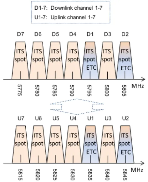
Figure 5 shows the channel assignment on 5.8 GHz in Japan.
There are seven pairs of channels on 5.8 GHz band. The ETC system uses two pairs, the D1, U1 and the D2, U2. The ITS-spot system uses all of them. Since the ETC tollbooths are away from the ITS-spot roadside units, the ETC system and the ITS-spot system can share the same radio channels.
There are other services which can be provided by the ITS-spot system. For example, the ITS-spot system may provide payment service at a parking lot or a drive-through store as long as the ITS-spot roadside unit is installed. The ITS-spot system also can be utilized for road traffic informa- tion gathering. So far the VICS system relies on sensors and cameras on the road to obtain the road traffic information at a particular location. Since the ITS-spot roadside units can exchange information with each individual vehicles using wireless communication, the travel time between two ITS- spot roadside units for each vehicle can be calculated very precisely. If the privacy of each individual vehicle can be protected, the ITS-spot system can be a very good system to gather real-time road traffic information.
Since the ITS-spot system has very close relationship with the VICS system and the ETC system, it is possible to create a combo radio system to combine ITS-spot, VICS and ETC together to reduce the cost. The shipment of this type of new in-vehicle device will start shortly. But it may take
Fig. 5 The channel assignment of the ITS-spot and the ETC.
time for current users to replace the old in-vehicle device for new one.
3. Future ITS
3.1 Future ITS in Japan
Automakers developed lots of stand-alone vehicle safety system, e.g. ABS (Anti Lock Brake System), VSC (Vehicle Stability Control) to reduce the traffic accidents. However stand-alone safety systems are not sufficient all the time.
Recently, R2V (roadside-to-vehicle) and V2V (vehicle-to- vehicle) communications have drawn much attention for be- ing possibly achieving better safety assistance to drivers by exchanging safety related messages between neighboring vehicles or between vehicle and roadside infrastructure to extend driver’s view. Figure 6 shows the typical applications for R2V and V2V communications. The typical application for vehicle-to-vehicle safety communication is blind inter- section collision avoidance, especially under NLOS (Non- line-of-sight) situation. Each vehicle broadcasts its loca- tion, speed, heading and acceleration information periodi- cally (e.g. 100 ms) to inform neighboring vehicles about its presence. On the other hand, traffic signal violation warning is a very good example for roadside-to-vehicle communi- cation. In this case, the roadside unit periodically broad- casts traffic signal information to the vehicles around an in- tersection. There are also lots of other applications being discussed based on the same concept.
In order to realize the R2V and V2V communica- tions, similar activities, such as radio frequency assignment, demonstration experiment and radio system development, have been carried out in the USA, Europe and Japan.
In Japan, the 10 MHz band from 715 MHz and 725 MHz was assigned for ITS in Telecommunications Council Report in July 2007. Later in 2011, the ITS band
Fig. 6 The typical applications for R2V and V2V communications.
Table 4 The characteristics of 700 MHz band ITS.
was changed to 755-765 MHz due to the change of radio frequency assignment plan in 700 MHz-band and 900 MHz- band. In Aug 2011, the Information and Communications Council approved ITS system as a new radio system on 700 MHz band in Japan. In Dec 2011, the Radio Regula- tory Council also approved the use of 700 MHz band for ITS. Based on these approvals, ARIB developed the radio communication standard for it, and published the standard as ARIB STD-T109 in Feb 2012, which title is 700 MHz band intelligent transport systems [14]. Some characteris- tics defined in ARIB STD-109 are shown in Table 4. The 700 MHz band ITS uses OFDM as modulation method and CSMA/CA as medium access control method, the same as IEEE 802.11.
In 2008, large-scale vehicle-to-vehicle communication experiments were planed at the office of the Prime Min- ister [15], and carried out by Ministry of Internal Affairs and Communications, National Police Agency, Ministry of Land, Infrastructure, Transport and Tourism, and automak- ers. The results of the experiments showed that vehicle-to- vehicle communication prototype systems accomplished the application requirement (95% reachability in 5 m) even un- der a congested environment with hands of vehicles com- municating with each other [16]. Other testing results in ur- ban area, e.g. the experiments in Ginza, Tokyo were also reported in recent years showing the communication perfor- mance is good enough for system implementation [17].
The 700 MHz band ITS are moving toward realization.
The large-scale proof-of-concept demonstration will be car- ried out in 2013 followed by the show case in ITS world congress in Tokyo. The commence operations will start in 2014.
3.2 Future ITS in US and EU
In the US, DSRC is emerging as a critical vehicular commu- nication technology. Based on the popular IEEE (Institute of Electrical and Electronics Engineers) 802.11 (WiFi) proto- col, DSRC uses licensed spectrum in the 5.9 GHz band to enable vehicles to communicate with other vehicles (V2V) and with roadside infrastructure devices (V2I) over dis- tances of a few hundred meters. This communication sup- ports a wide variety of applications, often broadly catego- rized as safety, mobility, environment, and entertainment.
The primary focus of DSRC research among automak- ers, government officials, and other stakeholders is collision avoidance. When a vehicle broadcasts its core mobility state
information, i.e. location, speed, heading, acceleration, etc., neighboring vehicles can use that information to predict po- tential collision threats, warning the driver or even taking control of the vehicle (e.g. automated braking). The U.S.
Department of Transportation (DOT) estimates that V2V collision avoidance can impact 82% of multi-vehicle crashes involving non-impaired drivers [6]. Driving safety can also be improved via V2I applications, e.g. stop light warning, curve speed warning.
The outdoor, high velocity vehicular environment poses unique data communication challenges, including fad- ing, delay spread, and short duration interactions. Automak- ers have demonstrated the feasibility of DSRC for collision avoidance in a variety of scenarios [18] based on a set of in- teroperability standards [19]. They are participating in a one year US DOT-sponsored “Model Deployment” in Michigan to measure the effectiveness of the technology, using 3000 DSRC-equipped vehicles. Current research is investigating several issues, including scalability and security. Scalabil- ity addresses the efficacy of safety communication in high vehicle density environments; channel congestion control is a particular focus. Security issues include authentication of messages, preservation of driver privacy, and requirements involving communication between vehicles and security in- frastructure devices.
European automakers and standards bodies are consid- ering very similar technologies to those being tested in the US. In Japan the technologies for vehicle safety communi- cation have some common features with the US and Europe, but also important differences (e.g. spectrum, upper layer protocols, security).
Extensions of DSRC to non-safety applications will provide additional benefits in the future. V2V applications include platooning and eventually autonomous driving. Po- tential V2I applications are abundant, though in some cases cellular communication may provide more efficient service delivery.
V2V and V2I communication based on 5.9 GHz DSRC is nearing the end of its pre-deployment phase in the US and in Europe. First generation systems are likely to be just that, the first of several generations, each more capable and more enabling than the last. The future is expected to bring an ex- panding set of applications, moving beyond collision avoid- ance. Indeed, many of these applications have been part of the vision for DSRC-based ITS all along [20]. The promise of fewer accidents and fatalities makes DSRC deployment in vehicles possible, and deployment in turn opens the door to a wide variety of additional benefits.
Next generation DSRC applications are often classified in the following (overlapping) categories:
• Mobility: helping the driver find a destination and reach it quickly and efficiently. Examples include real-time navigation and emergency vehicle alerts.
• Environment: reducing fuel consumption and damag- ing emissions. Examples include green light speed ad- visory and platooning.
• Commerce: advertising the availability of goods and services and providing a means to complete transac- tions. Examples include electric charging station avail- ability and drive-thru payments.
• General: This includes the important category of
“things not yet conceived.” The lesson from smart- phones is that new communication tools often lead to unexpected areas of innovation.
Two potential obstacles to widespread deployment of these applications are: a) lack of DSRC roadside equipment offering services and providing backhaul, and b) alterna- tive communication channels, principally cellular. Indeed, when DSRC and cellular systems both satisfy an applica- tion’stechnicalrequirements (e.g. speed and latency), busi- ness, policy, and governance issues may determine the best choice. Proximity between communication endpoints ap- pears to be one important indicator, for example DSRC has a natural advantage when the service can be delivered over one hop.
Technical challenges include: maintaining backward compatibility across generations, updating the capabilities of older vehicles, and integrating communication and sensor technology. The former is largely a standards issue, while the latter two tasks will be addressed by vehicle manufac- turers individually.
3.3 Further Future of Vehicular Networks with Diverse Spectral Needs
As the number of vehicles and applications using the ded- icated ITS spectrum increase, one can expect substantial growth in the bandwidth and capacity requirements. Even- tually, such applications might suffer from spectrum scarcity and overcrowding, as has already been experienced by other mobile wireless communications sectors. This motivates re- cent efforts to look for spectral resources elsewhere. It is very important for DSA to ensure the rights of the incum- bent spectrum license holders are respected. One method of achieving DSA functionality is cognitive radio, which em- ploys autonomous communications techniques. Existing so- lutions in the cognitive radio domain usually assume no mo- bility, which is a major challenge to be overcome in vehicu- lar settings. Moreover, all of the existing cognitive radio ar- chitectures and standards are centralized around a base sta- tion or a variant where a master-slave relationship between the base station and the end-user terminals governs the entire flow of events. This type of architecture is of less interest in a dynamic vehicular environment where most of the com- munications is expected to occur among vehicles without the intervention of a centralized component.
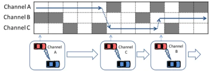
In the vehicular environment, application of cognitive radio principles can help to satisfy capacity demand for ITS applications; and to offload time-insensitive applica- tions from the ITS dedicated spectrum. Broadcast televi- sion spectrum is one of the possible candidates for dynamic spectrum access in vehicular environments owing to its rel-
Fig. 7 Cognitive V2V communications concept.
atively static channel utilization by the incumbents. A con- ceptual overview of V2V communications over white spaces is shown in Fig. 7 where vehicles switch between unused chunks of spectrum.
Before anything, vehicular cognitive network nodes must be aware of the spectrum holes (white space) around them in order to opportunitistically utilize the otherwise unused spectrum. Two approaches being considered for spectrum awareness are incumbent user signal sensing and geolocation database lookup. Both approaches pose ad- vantages and drawbacks in vehicular environments. More specifically, neither of these approaches individually can provide sufficient incumbent protection from interference that might be created by vehicular cognitive network nodes [21]. Towards merging spectrum sensing with geolo- cation database lookup, a representation method of white space vectors customized for high mobility environments is studied in [22]. Once the spectrum holes are detected, the next step is to coordinate and agree with the other ve- hicle (s) on the channels that are suitable for communica- tions. One of the first studies that looked into the poten- tial of using white spaces for vehicular communications is [10]. In [10], a distributed and autonomous dynamic spec- trum coordination method tailored for vehicular environ- ments is proposed. Vehicles coordinate to agree on a con- trol channel, to subsequently setup data channels, and from there to further exchange information on spatial and tem- poral spectrum variations. Vehicles in this method make use of each other’s temporal and spatial proximity relation- ships to autonomously agree on control and data channels.
[23] reported and demonstrated the world’s first field tests of vehicle-to-vehicle communications over TV white space between two moving vehicles. Furthermore, [11] investi- gates the spatial dependencies in selecting an appropriate vacant channel for multi-hop vehicle-to-vehicle communi- cations by taking into account several factors, such as the distance between the vehicles, channel bit rate, vehicle ve- locities, statistical information of channel utilization and propagation range of candidate channels. [24] describes a combination and extension of the work in [23], with the dis- tributed and autonomous control and data channel selection algorithms tailored for a group of vehicles and multi-hop communications.
Moreover, [25] looks into the feasibility of performing vehicular dynamic spectrum access across vacant TV chan- nels. It leverages actual quantitative measurements obtained from a wireless spectrum measurement campaign conducted
along a major interstate highway in Massachusetts. The re- sults show that in most rural and suburban areas, TV white space is a feasible resource for vehicle communications, sat- isfying performance requirements assuming that the sensing and channel switching functions are performed sufficiently fast. [26] further advances the concept of vehicular dynamic spectrum access by employing artificial intelligence meth- ods such as machine learning, to make a vehicle gradually learn from the past spectral experience and hence quickly converge into the best performing channel depending on the application requirements.
4. Conclusion
This paper has presented an overview of the current and fu- ture ITS. Current ITS are spreading year by year. In Japan the penetration rates of VICS and ETC are about 20% and 50% respectively. On the other hand, the penetration of mo- bile devices and the advance of mobile device technologies have been astonishing. The number of wireless subscriber connections surpasses the total Japanese population. Mobile payment including instantaneous payment has become very popular. Real-time traffic data based on GPS-enabled smart- phones monitoring can be shown on mobile devices such as smartphones or tablets. Cooperation with mobile device technologies should be taken into account for the next re- newal systems. Decision and penetration of the future ITS will also be affected by costs. However as the future ITS are closely related to safety supports and the numbers of fatalities from traffic accidents totaled in recent years were around 5000 in Japan, rapid penetration will be strongly ex- pected. Considering preparation against aging society, auto- matic vehicle operation systems are very attractive. To sup- port such systems, beyond-future ITS should also be consid- ered early.
References
[1] How VICS works, http://www.vics.or.jp/english/vics/index.html [2] How to use ETC, http://www.orse.or.jp/english/index.html [3] A brief overview of ETC in a beep,
http://www.go-etc.jp/english/index.html [4] Distribution of ITS-spot roadside unit
http://www.mlit.go.jp/road/ITS/j-html/spot dsrc/ tenkai.html#tenkai1
[5] ITS Activities at the Ministry of Internal Affairs and Communica- tions in Japan, 2007; http://www.soumu.go.jp/main sosiki/ joho tsusin/eng/presentation/pdf/071012 1.pdf
[6] US DOT, RITA, ITS JPO, Connected Vehicle Research, http://www.its.dot.gov/connected vehicle/connected vehicle.htm [7] H. Yoshino, “ITU-R standardization activities on cognitive radio,”
IEICE Trans. Commun., vol.E95-B, no.4, pp.1036–1043, April 2012.
[8] B. Babadi and V. Tarokh, “Distributed dynamic spectrum allocation for secondary users in a vertical spectrum sharing scenario,” IEICE Trans. Commun., vol.E95-B, no.4, pp.1044–1055, April 2012.
[9] M.A. Rahman, C. Song, and H. Harada, “Sensing methods for de- tecting analog television signals,” IEICE Trans. Commun., vol.E95- B, no.4, pp.1066–1075, April 2012.
[10] K. Tsukamoto, S. Matsuoka, O. Altintas, M. Tsuru, and Y. Oie,
“Distributed channel coordination in cognitive wireless vehicle-to- vehicle communications,” Proc. Int. Conf. on Wireless Access in Vehicular Environment (WAVE 2008), Dearborn, MI, USA, Dec.
2008.
[11] K. Tsukamoto, Y. Omori, O. Altintas, M. Tsuru, and Y. Oie, “On spatially-aware channel selection in dynamic spectrum access multi- hop inter-vehicle communications,” Proc. IEEE Vehicular Technol- ogy Conf. 2009-Fall, Anchorage, AK, USA, Sept. 2009.
[12] ARIB STD-T55 (English)
http://www.arib.or.jp/english/html/overview/doc/ 5-STD-T55v1 0-E.pdf
[13] ARIB STD-T75 (English)
http://www.arib.or.jp/english/html/overview/doc/ 5-STD-T75v1 0-E2.pdf
[14] ARIB STD-T109
http://www.arib.or.jp/english/html/overview/doc/ 1-STD-T109v1 0.pdf
[15] The work plan of the large-scale vehicle-to-vehicle experiments, http://www.kantei.go.jp/jp/singi/it2/others/
its safety2010-keikaku.pdf
[16] The development of drive-assistant road safety system in Japan http://www.ieee-jp.org/japancouncil/chapter/VT-06/vt.files/ VTS-ITS20100623-3.pdf
[17] S. Sai, et al., “Field evaluation of UHF radio propagation for an ITS safety system in an urban environment,” IEEE Commun. Mag., vol.47, no.11, pp.120–127, Nov. 2009
[18] NHTSA, Vehicle Safety Communications – Applications (VSC-A) Final Report, DOT HS 811 492A, Sept. 2011.
[19] J. Kenney, “DSRC standards in the United States,” Proc. IEEE, vol.99, no.7, pp.1162–1182, July 2011.
[20] US National ITS Architecture (ITS America).
[21] H. Kremo, R. Vuyyuru, and O. Altintas, “Spectrum sensing in the vehicular environment: An overview of the requirements,” Proc.
SDR’12-WInnComm-Europe, Brussels, Belgium, June 2012.
[22] K. Inage, S.N. Lee, T. Fujii, and O. Altintas, “White space vec- tors for channel selection in vehicular cognitive networks,” Proc.
IEEE Vehicular Networking Conf, Amsterdam, The Netherlands, Nov. 2011.
[23] O. Altintas, M. Nishibori, T. Oshida, C. Yoshimura, Y. Fujii, K.
Nishida, Y. Ihara, M. Saito, K. Tsukamoto, M. Tsuru, Y. Oie, R.
Vuyyuru, A. Al Abbasi, M. Ohtake, M. Ohta, T. Fujii, S. Chen S.
Pagadarai, and A.M. Wyglinski, “Demonstration of vehicle to ve- hicle communications over TV white space,” Proc. IEEE Vehicular Technology Conf. - Fall, San Francisco, USA, Sept. 2011.
[24] O. Altintas, Y. Ihara, H. Kremo, H. Tanaka, M. Ohtake, T. Fujii, C. Yoshimura, K. Ando, K. Tsukamoto, M. Tsuru, and Y. Oie,
“Field tests and indoor emulation of distributed autonomous multi- hop vehicle-to-vehicle communications over TV white space,” Proc.
ACM MobiCom 2012, Istanbul, Turkey, Aug. 2012.
[25] S. Chen, A. Wyglinski, S. Pagadarai, R. Vuyyuru, and O. Altintas,
“Feasibility analysis of vehicular dynamic spectrum access via queueing theory model,” IEEE Commun. Mag., vol.49, no.11, pp.156–163, Nov. 2011.
[26] S. Chen, R. Vuyyuru, O. Altintas, and A. Wyglinski, “On optimiz- ing vehicular dynamic spectrum access networks: Automation and learning in mobile wireless environments,” Proc. IEEE Vehicular Networking Conf., Amsterdam, The Netherlands, Nov. 2011.
Seii Sai received the B.S. and M.S. degrees in Information and Communication Engineer- ing from the University of Tokyo in 1999 and 2001, respectively. Currently he is a senior re- searcher at Toyota InfoTechnology Center, Co., Ltd. His research interests include ITS system architecture, vehicle-to-vehicle communication methods, and routing protocols.
Onur Altintas is a principal researcher at Toyota InfoTechnology Center, Co. Ltd. He re- ceived his B.S. and M.Sc. degrees from Orta Dogu Teknik Universitesi, Ankara, Turkey, and his Ph.D. degree from the University of Tokyo, Japan; all in electrical engineering. He is the co- founder and general co-chair of the IEEE Vehic- ular Networking Conference (IEEE VNC). He is an IEEE VTS Distinguished Lecturer.
John Kenney received the B.S. and Ph.D.
degrees in electrical engineering from the Uni- versity of Notre Dame in 1982 and 1989, respec- tively, and the M.S. degree in electrical engi- neering from Stanford University in 1983. He is a Senior Research Manager at Toyota InfoTech- nology Center, USA. His current research is in wireless congestion control and performance of vehicular networks. His prior research inter- ests include adaptive systems, high speed packet switching, and Internet quality of service.
Hideaki Tanaka received B.E., M.E., and Ph.D. degrees in electronics engineering from Osaka University, in 1984, 1986, and 1997, re- spectively. In 1986, he joined Kokusai Den- shin Denwa (KDD) R&D Laboratories (cur- rently KDDI R&D Laboratories), Tokyo, Japan.
From 1986 to 2011, he was engaged in research on high-speed semiconductor modulators, their integrated devices, design of optical submarine cable systems, optical access technologies, and ICT resource management. Since 2011, he has been with the Toyota InfoTechnology Center, Tokyo, Japan. His current re- search is in wireless systems and networks for vehicle. Dr. Tanaka received the Best Paper award from the Opto-Electronics Conference in 1988, the distinguished paper award from IEICE in 1995, Minister Award of Ad- vanced Technology from METI (Ministry of Economy, Trade and Industry of Japan) in 2006, and Sakurai Memorial Prize from OITDA in 2009.
Yuji Inoue was born in 1948 in Fukuoka, Japan. He received the B.E., M.E. and Ph.D. de- grees from Kyushu University, Fukuoka, Japan, in 1971, 1973 and 1986, respectively, and was made an Honorary Professor of the Mongolian University of Science and Technology in 1999.
He joined NTT Laboratories in 1973 and served there for 34 years. While he was in NTT, he was active in ITU-T standardization on ISDN (Inte- grated Services Digital Network), SDH (Syn- chronous Digital Hierarchy) and TNA (Trans- port Network Architecture) during 1982 – 1992. After new business de- velopment in NTT Data, he was a board member of NTT in 5 years as CTO and the head of NTT group’s R&D with 6000 researchers and engi- neers..He moved to The Telecommunication Technology Committee, TTC in 2007 as the President and CEO, then to Toyota InfoTechnology Center.
He is currently the Chairman of the Board. He is a fellow of IEEE and is currently President Elect of IEICE. He wrote and edited many technical books.