Experiments on the Excitation of the Electron Waves by a Slow Waveguiding Circuit
journal or
publication title
福井大学工学部研究報告
volume 27
number 2
page range 233‑237
year 1979‑09
URL http://hdl.handle.net/10098/4422
FUKUI UNIVERSITY
VOL.27 No. 2 1979
Experiments on the Excitation of the Electron Waves
by
a Slow Waveguiding Circuit
Toshitaka
IDEHARA~
Haruyuki HAYASHI* and Yoshio ISHIDA*(Received July 3, 1979)
The excitation of the electron plasma wave in a magnetized plasma (Trivelpiece-Gould mode) is investigated experimentally, by using the slow waveguiding circuit (SWC) surrounding the plasma column. The wave vector of the excited wave can be controlled externally.
In a recent few years, the further heating of the magnetically confined plasmas to thermonuclear temperature by using a high power source with a fre- quency w/2n near the lower hybrid frequency, has been investigated with great interests. For the launched wave to penetrate through the plasma boundary without significant reflection, it is desired that the parallel phase velocity of the wave, w/kz (where k
z is the wave vector component parallel to the mag- netic field B=BZ) is much smaller than the velocity of light c. This requir- ment has been attained by using a finite-length slow waveguiding circuit (SWC).
The propagation of the lower hybrid wave excited by SWC and the mode con-
. 1) 2)
vers~on near the resonance layer were analyzed by several authors.' On the other hand, it is observed that SWC surrounding the plasma column excites the wave, which propagates in the region of inhomogeneous density distribution and reaches the resonance layer.3) ,4) The experimental results can be explained consistently by the theoretical analysis.
This method for the wave excitation has an advantage that the parallel com- ponent of the wave vector k
z can be controlled externally and fixed dt a suit- able value through an experimental study, While, it can not be controlled in the familiar method where the coaxial probe is used for the wave excitation.
Considering these points, we will try to apply the former method to the detailed study of the high frequency, electron wave, that is, the Trivelpiece-Gould mode.S
) The possibility has been discussed in the previous
paper~)
where the equi-phase lines and damping factor of the excited electron wave are calculated numerically.In this paper, the experimental study of the excitation of electron plasma waves by using SWC is reported .
• t. Department of Applied Physics
234
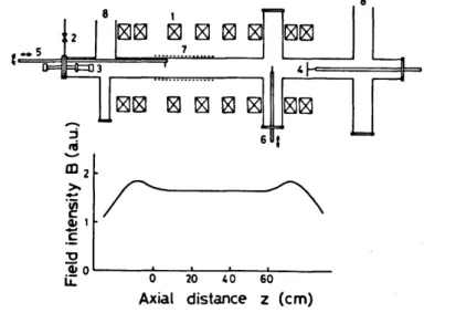
The experimental apparatus used through the experiments is shown in Fig.l.
The plasma is produced by the dc discharge and confined magnetically at the center of the plasma chamber, which consists of the pyrex glass tube of 95 mm in diameter and 1600 mm in length. Argon gas is fed continuously through a needle valve and pumped by two 4 inch diffusion pumps, the pressure p at the plasma region being maintained at 1 - 4 x 10⁻⁴
Torr. The magnetic field is applied along the tube axis by eight air-core coils, whose intensity distribution is shown in the figure. The plasma parameters are as follows, the plasma frequency w
pO/2TI on the axis of the tube iS 2
1.1 - 4.3 x 10²
MHz and the electron cyclotron frequency w /2TI is 1.6 - 5.1 x 10 MHz.
c
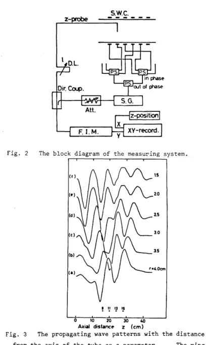
As shown in Fig. 2, SWC which consists of 16 ring electrodes spaced 2 cm apart, surrounds the glass tube. The wave signal from the signal generator whose frequency w/2TI is varried from 25 to 500 MHz, is divided into eight signals by three power splitters. They are applied to SWC, so that the ring electrodes have their phase alternate by 1800 (TI-mode). This setup launches a four- wavelength-long axial wave train (2TI/k
=
4 cm) having w/k «c. Waves excitedz z
inside the ring structure are detected by a coaxial probe movable axially.
By using the interferometer system, the propagating wave patterns along the field (along the axial direction Z) are observed.
Fig. 3 shows typical interferometer traces in the frequency range of w<w , c
~_5
Fig. 1
2
al
z
...
~.
~ ClJI...
. f"0 8
l8J~
l8J18I
1
rgj rgj ~ ~ ~rgj ... ~.
... 4
rgJ
~ ~ tgJ ~~6
£
0 0 20 40 60Axial distance z (cm)
8
The experimental apparatus and the distribution of the applied magnetic field. 1. air-core coils, 2. needle valve, 3. cathode, 4. anode, 5. movable z-probe, 6. movable r-probe, 7. slow waveguiding circuit and 8. 4 inch diffusion pumps.
z-
Fig. 2 The block diagram of the measuring system.
! '! '! I~
o 10 20 30 40 Axial distance- z (em)
Fig. 3 The propagating wave patterns with the distance r from the axis of the tube as a parameter. The ring electrodes denoted by 9, 11, 13 and 15 are used.
W/2i1= 25 MHz, Wc/2rr= 420 MHz and Wpo/2l'f= 130 MHz.
236
with the radial distance r from the axis as a parameter. Here, four rings denoted by 9, 11, 13 and 15 are used, so that a two-wavelength-long wave train
(2n/k = 8 cm) is launched. When the wave propagates in the plasma, the axial z
position z of the wave packet shifts with the radial distance r. Two waves propagating both +z and -z directions are excited in the n-mode operation.
The waVp. number k
z and the length of a wave train are controlled externally, by the aperture and the number of used ring electrodes.
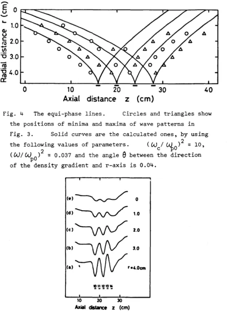
In Fig. 4, the axial position of the minima (circles) and maxima (triangles) of the observed traces are plotted as functions of the radial distance r.
Lines connecting the minima (or maxima) show the equi-phase lines. The solid lines show the theoretical results for the equi-phase lines, which are calculated by assuming two dimensional model as follows.
where
The wave equation can be written as follows,
w 2 P 2 2 ' w - w
c
w 2
KII
= 1 ,--+
I.J..\0,
and w varries along rand z directions with the plasma density n(r,z).
p
Actua] density profile n(r,z) measured by Langmuir probe is used, when eq. (1) is calculated numerically and the equi-phase lines are determined.
The experimental results are fairly good agreement with the theoretical pre- dictions. This fact shows that the electron plasma wave (Trivelpiece- Gould mode) may be excited by using SWC and, therefore, its wave number k z can be controlled externally.
Fig. 5 shows interferometer traces in the frequency range of w>wc' The axial shift of the wave packet with the radial distance r can not be observed, which means that the standing plasma wave is excited in the fre- quency range. The detailed study in this case is under way.
1) 2) 3)
R.J.
P.M.
P.M.
Briggs and Bellan and Bellan and
References
R.R. Parker, Phys. Rev. Letters 29 (1972) 852.
M. Porkolab, Phys. of Fluids 17 (1974) 1592.
M. Porkolab , Phys. Rev. Letters 34 (1975) 124.
4) M. Fukushima, Y. Terumichi and S. Tanaka, Kakuyugo Kenkyu 34 (1975) 438. (in Japanese)
5) A.W. Trivelpiece and R.W. Gould, J. Appl. Phys. 30 (1959) 1784.
6) T. Idehara, Jap. J. Appl. Phys. to be published.
-
E u 0-
"-to
G.I u c 2.0
-
.~ Iil"0 3.0
Iii
~4.0 a:o
10 3040
Axial distance z (em)
Fig. 4 The equi-phase lines. Circles and triangles show the positions of minima and maxima of wave patterns in Fig. 3. Solid curves are the calculated ones, by using the fOllO~ing values of parameters. (~c/ ~O) 2 = 10,
(~/UJpO)
=
0.037 and the anglee
between the direction of the density gradient and r-axis is 0.04.,
o
(d)~'.O
(C)~2.0
(.)~,.o
(.)~ .... o ...
10 20 30
Axial distance z (em)
Fig. 5 The propagating wave patterns with the distance r from the axis of the tube as a parameter.
Wc/2 Ti = 370 MHz and W
po/21T = 250 MHz.
w/2 .. =500 MHz,
238