著者
Kojima Takafumi
内容記述
学位授与大学: Osaka Prefecture University(大阪
府立大学), 学位の種類: 博士(理学), 学位記番号:
論理第85号, 学位授与年月日: 2010-03-31, 指導
教員: 小川英夫.
Quantum-limited 0.78–0.95-THz Waveguide SIS Mixers
for the ALMA Band 10 Receivers
Takafumi Kojima
February, 2010
Abstract
This thesis describes the demonstration and the application of a low noise Superconduc-tor-Insulator-Superconductor (SIS) mixer for the Atacama Large Millimeter/submillimeter Array (ALMA) band 10 covering the frequency range of 0.787-0.950 THz. The ALMA is one of the largest ground-based astronomy projects for the next decade. The ALMA telescope covers atmospheric windows in the frequency range from 30 GHz to 0.95 THz, which is divided into 10 frequency bands. Band 10 receivers of the ALMA, which is the highest frequency band, are expected as a key frequency band, e.g. for imaging observations with the very high angular resolution to detect the gaps created by planets undergoing formation in the disk. To enable such a challenging observation, band 10 receivers requires ultimate performance with a Double SideBand (DSB) noise temperature below 230 K (5hf/kB) for 80% bandwidth and 344 K (7.5hf/kB) for 100% bandwidth
over the 4–12 GHz intermediate frequency (IF) band. The final goal of this study is to develop low noise and wideband SIS mixers so as to meet the specifications and to enable such challenging observation of ALMA band 10 by demonstrating high performances for each component.
SIS junctions should be the most sensitive mixing elements in this frequency. However, there have been no mixers currently available that satisfy the requirements of both low noise and wideband operation for the ALMA band-10 specification. This is because, thus far, well-established all-Nb SIS mixers can not be used due to radio frequency (RF) losses in their microstrip tuning circuits which increase significantly as a result of the onset of pair-breaking above the Nb gap frequency of 0.7 THz. For example, RF signals are attenuated by more than 60 % per the wavelength in this frequency range. Besides, the RF fractional bandwidth of about 20 % is a critical problem for achieving the specifications as well as the quantum limited sensitivity. Since an SIS junction has a large capacitance, RF bandwidth might be limited by RC. For this reason, it might have been
believed that the SIS junction’s current density (Jc) is the most important factor to make the RF
bandwidth wider. This implies that high Jc (>20 kA/cm2) SIS junctions with very thin barrier have to
be developed.
For solving these issues, we have performed the investigation in detail by both design and fabri-cation approach. Chapter 1 offers introduction to show the importance and position of this thesis. In chapters 2 and 3, theoretical verification and feasibility of material combination for the band 10 mixers are discussed. Chapter 4 presents investigation of SIS mixers with Nb/AlOx/Nb junctions and
new microstrip configuration using epitaxial NbTiN films and normal metal. The device based on NbTiN showed a receiver noise temperature of 171 Kat 0.83 THz. On the other hand, the detailed analysis of mixers on the basis of numerical simulations was consistent with the experiment results, and it revealed a possibility of further improvement in the mixer performance. Chapter 5, which is
the core of this thesis, describes the demonstration of a wideband and low-noise SIS mixer satisfying for the ALMA band-10 specification. The SIS mixer adopted Nb/AlOx/Nb junctions with a moderate
current density of 8 kA/cm2 and low loss NbTiN/SiO2/Al inverted microstrip lines. Optimal
impedances of the twin-junction circuit are theoretically investigated so as to achieve both low noise and wideband performances simultaneously. The heterodyne measurement results of this type of device showed quantum limited mixer sensitivity and wide bandwidth. Chapter 6 presents the design and the analysis of low-noise IF systems using state-of-the-art noise amplifiers and low-loss isolators. In addition, the improvement of frequency dependence of IF noise temperature and output power by detailed system consideration including the SIS mixer will be described. Chapter 7 provides the development of a waveguide SIS mixer incorporating LO directional coupler. The insertion loss of the waveguide and coupling factor of the LO coupler were evaluated at both room and cryogenic temperatures. The mixer block was designed on the basis of the characterization. Finally, we present the result of achieving ALMA band 10 specification. Chapter 8 summarizes the achievement described in this thesis. Low-noise waveguide SIS mixers developed in this work will be installed for the ALMA band 10 receivers. In addition, we believe the instrument and the technologies of the design, fabrication, and measurement will be applied for a variety of high frontier terahertz fields.
Contents
Abstract ... i
Chapter 1 ... 1
Introduction ... 1
1.1 Terahertz detectors ... 1
1.2 Atacama Large Millimeter/submillimeter Array ... 1
1.3 ALMA band 10 ... 4
1.3.1 A scientific interest at the band 10 frequencies ... 4
1.3.2 ALMA band 10 cartridge receiver ... 5
1.3.3 Receiver specification ... 7
1.3.4 Other heterodyne Instruments at similar frequency to ALMA band 10. ... 7
1.4 Heterodyne receiver ... 8
1.4.1 SIS quasi-particle mixers ... 9
1.4.2 Receiver sensitivity ... 10
1.5 Key technologies and problems ... 11
1.5.1 Low noise and wideband SIS mixers ... 12
1.5.2 Wideband IF chain of 4-12 GHz ... 13
1.5.3 Low loss waveguide components and efficient usage of LO Power ... 14
1.6 Overview of this thesis ... 15
References ... 16
Chapter 2 ... 19
Fundamental theory of heterodyne SIS mixer ... 19
2.1 Overview ... 19
2.2 SIS junction as a mixing element ... 19
2.2.1 General mixer theory ... 19
2.2.2 Quasi-particle tunneling current in SIS junction ... 26
2.2.3 Three port quantum mixing theory ... 29
2.3 Superconducting microstrip line ... 32
2.3.1 Surface impedance of superconductors and normal conductors ... 33
2.3.2 Analytical calculation method of superconducting microstrip lines ... 34
2.3.3 Numerical simulation of a superconducting microstrip line using HFSS ... 36
2.3.4 Power transmission calculation to junctions using transmission matrix ... 38
2.4 Receiver noise measurement ... 40
2.4.2 Test receiver ... 41
References ... 42
Chapter 3 ... 45
Material selection and feasibility study on SIS mixers for the ALMA band 10 ... 45
3.1 Overview ... 45
3.2 Practical application limitation of SIS junctions ... 45
3.3 Material selection for tuning circuit ... 48
3.4 Suitable tuning circuit for the ALMA band 10 ... 50
3.5 RF bandwidth and optimum Junction current density ... 51
3.6 SIS mixer fabrication ... 52
3.6.1 Film properties for superconductor and normal conductor ... 52
3.6.2 X-ray diffraction patterns ... 54
3.6.3 Resistance-temperature characteristic and residual resistance ratio ... 55
3.6.4 Properties of Al films ... 55
3.6.5 Sequence of process steps ... 56
3.6.6 Mixer chip fabrication ... 57
3.7 Current-voltage characteristics and resonance step ... 58
References ... 59
Chapter 4 ... 63
Development of waveguide SIS mixers based on epitaxial NbTiN films on MgO substrates ... 63
4.1 Overview ... 63
4.2 Design ... 63
4.3 Evaluation of the mixer ... 66
4.4 Improved design ... 69
4.4.1 Higher mode and choke filter design ... 69
4.4.2 Probe design... 71
4.4.3 Mixer chip and tuning circuit design ... 71
4.5 Mixer performance and discussion ... 73
4.6 Conclusion ... 75
References ... 75
Chapter 5 ... 77
Demonstration of a low-noise waveguide NbTiN-based SIS mixer on a quartz substrate ... 77
5.1 Motivation and Overview ... 77
5.2 Wideband and low-noise SIS mixer design ... 79
5.2.1 Mixer chip design ... 79
5.2.3 Optimum noise match design based on RF embedding analysis ... 82
5.3 Mixer performance ... 85
5.3.1 Source impedance dependence ... 85
5.3.2 Optimal bias point for the receiver noise and the mixer gain ... 87
5.4 Fourier transform spectrometer measurement ... 88
5.4.1 Fourier transform spectrometer ... 88
5.4.2 FTS measurement ... 89
5.5 Mixer performance analysis ... 92
5.5.1 Bandwidth limitation ... 92
5.5.2 Estimation of noise parameters for the twin-junction circuit at LO 0.88 THz ... 92
5.6 Performance at an operating temperature of 2 K ... 95
5.7 Conclusion ... 96
References ... 97
Chapter 6 ... 101
Consideration of 4–12 GHz optimum IF circuits for the band 10 mixers ... 101
6.1 Motivation and Overview ... 101
6.2 Characterization of the IF components ... 101
6.2.1 4-12 GHz IF component used for the band 10 receivers ... 101
6.2.2 Noise temperature measurement using cryogenic attenuator ... 103
6.3 IF circuits for band 10 SIS mixers ... 105
6.3.1 Design of two IF circuits ... 105
6.3.2 Calculation of the receiver noise temperature ... 106
6.4 Measurement results and the analysis ... 107
6.4.1 Shot noise measurement ... 107
6.4.2 Receiver noise temperature for two circuit designs ... 108
6.4.3 Receiver noise temperature for different bias conditions of the IF amplifier ... 109
6.4.4 Analysis ... 110
6.5 Improvement of IF characteristics ... 113
6.6 Conclusion ... 114
References ... 114
Chapter 7 ... 117
A low-noise waveguide SIS mixer incorporating 10-dB directional coupler ... 117
7.1 Motivation and Overview ... 117
7.2 Design and evaluation of the waveguide components ... 117
7.2.1 Evaluation of WR-1.2 waveguide losses at cryogenic temperature ... 117
7.2.4 Evaluation of the 10 dB coupler at room temperature ... 122
7.3 LO injection scheme for the band 10 cartridge ... 124
7.3.1 Consideration of waveguide and quasi-optical coupling scheme ... 124
7.3.2 LO chain for the band 10 cartridges ... 126
7.3.3 Preliminary test ... 128
7.4 Performance of the cartridge receiver engineering model ... 128
7.4.1 Current response of an SIS junction for LO signals ... 128
7.4.2 Receiver noise temperature ... 130
7.5 Prototype mixer for the prototype cartridge receiver ... 131
7.5.1 Prototype mixer block design ... 132
7.5.2 Horn-to-horn coupling measurement at room temperature ... 133
7.5.3 Heterodyne measurement sets in test cryostat ... 134
7.5.4 LO current response ... 134 7.5.5 Heterodyne measurement ... 135 7.6 Conclusion ... 138 References ... 139 Chapter 8 ... 141 Summary ... 141 Appendix A ... 145
Transmission loss for polyimide films and Teflon sheets ... 145
A.1 Overview ... 145
A.2 Measurement ... 145
A.3 Estimation of reflectivity for the beam splitter ... 146
Appendix B ... 149
Junction coupling measurement using an LO source ... 149
B.1 Overview ... 149
B.2 Investigation using large signal source ... 149
B.3 Comparison of coupling between two methods ... 151
Appendix C ... 153
Water absorption at the experimental room ... 153
C.1 Overview ... 153
C.2 Mixer performance measurement for two conditions ... 153
C.2.1 Junction current response measurement using an LO source ... 154
C.2.2 Noise temperature measurement ... 154
Appendix D ... 157
On optimization process of NbTiN films on quartz ... 157
D.1 Overview ... 157
D.2 Optimization process ... 157
Publications and research achievements ... 159
Acknowledgement ... 163
Chapter 1
Introduction
1.1 Terahertz detectors
Terahertz frequency sandwiched between microwave and lightwave is loosely defined from 0.1 THz to 10 THz. It is a high frontier region where remains one of the least tapped regions of the electromagnetic spectrum. Besides continuum emission, interstellar dust clouds likely emit some 40 000 individual spectral lines in the terahertz band, only a few thousand of which have been resolved and many of these have not been identified [1]. This is because that, so far, sensitivity issue of the detector and high absorption from especially water and oxygen has made it extremely difficult for significant propagation and detection of terahertz energy in almost all Earthly environments.
Progress of astronomical observation has been driven strongly by the development of new tech-nology and instrumentation with high sensitivity. Superconducting detectors has been studied for realizing such high sensitive observation. Kinetic Inductance Detectors (KIDs), Superconducting Transition Edge Sensor (TES) detectors, and Superconducting Tunnel Junction (STJ) as a direct detector, will show great capabilities for photometrical observation with low spectral observation of 3-10 by taking an advantage of high sensitivity due to large bandwidth and not limited by quantum noise. On the other hand, with the aims of spectroscopic or high spatial resolution observation, Superconductor-Insulator-Superconductor (SIS) and Hot Electron Bolometer (HEB) mixers as a heterodyne one are widely used for practical low-noise receivers of radio astronomy and remote sensing up to 0.7 THz.
The main goal of this thesis is to develop low-noise SIS mixer so as to meet very tough specifi-cations for the Atacama Large Millimeter/submillimeter Array (ALMA) Band 10 covering 0.787-0.950 THz. In this thesis, we present new technology development for terahertz circuit design, superconducting device fabrication, low-loss terahertz waveguide transmission technology, and their measurement method. Their technologies will be applicable to not only astronomical field but also biological and biomedical areas, security and so on as spreading effects.
1.2 Atacama Large Millimeter/submillimeter Array
The ALMA is one of the largest ground-based astronomical projects for the next decade [2]. The ALMA is being built by collaboration among Europe, Japan, and North America and the start of full operations is expected in late 2012. It is being constructed on the Atacama Desert of northern
Chile at an altitude of about 5000 m. ALMA consists of a homogeneous array of about fifty 12-m diameter antennas for the interferometer (12 m Array) and a set of four 12-m and twelve 7-m diameter ones for the Atacama Compact Array (ACA) [9] for realizing fidelity of imaging with mosaicing observation (see Fig. 1-1).
With excellent sensitivity and high resolution at a high dry location (see Fig. 1-2), ALMA will allow sensitive heterodyne observation in the range 31 GHz0.95 THz (0.30 mm) and is expected to have impacts on three important scientific fields, that is, the formation and history of galaxies, the formation of extraterrestrial planetary systems, including the emergence of the life, and the history of the universe for the Big Bang. The highest level science requirements for ALMA are:
1. The ability to detect spectral line emission from CO or C II in a normal galaxy like the Milky Way at a redshift of z = 3, in less than 24 hours of observation.
2. The ability to image the gas kinematics in protostars and protoplanetary disks around young Sun-like stars at a distance of 150 pc (roughly the distance of the star forming clouds in Ophiuchus or Corona Australis), enabling one to study their physical, chemical and magnetic field structures and to detect the tidal gaps created by planets undergoing formation in the disks.
3. The ability to provide precise images at an angular resolution of 0.1. Here the term precise image means representing within the noise level the sky brightness at all points where the brightness is greater than 0.1 % of the peak image brightness. This requirement applies to all sources visible to ALMA that transit at an elevation greater than 20 degrees.
Cryostat
Cartridge
Fig. 1-3 photograph of ALMA antenna, cryostat, and cartridge. Each receiver is packaged in the form of a cylindrical cartridge (right), which are mounted within a 4-K circular cryostat of radius approximately 1 m (center). The cryostat is located on at the cassegrain focus of the antenna (left)
Table 1-I Frequency coverage and sensitivity requirement of the ALMA frequency bands
NAOJ SRON NAOJ IRAM NRAO CUT NAOJ HIA TBD TBD Institute 230 168 90.5 66.5 37.5 30 23.5 17 14 7.5 Trx (DSB) over 80% (K) 0.19 0.18 0,26 0.29 0.26 0.26 0.26 0.32 0.29 0.29 Fractional Bandwidth 950 720 500 370 275 211 163 116 90 40 Highest Freq. (GHz) 869 660 442 323 243 187 144 100 79 35 Center Freq. (GHz) 787 602 385 252 211 163 125 84 67 30 Lowest Freq. (GHz) 10 9 8 7 6 5 4 3 2 1 Band NAOJ SRON NAOJ IRAM NRAO CUT NAOJ HIA TBD TBD Institute 230 168 90.5 66.5 37.5 30 23.5 17 14 7.5 Trx (DSB) over 80% (K) 0.19 0.18 0,26 0.29 0.26 0.26 0.26 0.32 0.29 0.29 Fractional Bandwidth 950 720 500 370 275 211 163 116 90 40 Highest Freq. (GHz) 869 660 442 323 243 187 144 100 79 35 Center Freq. (GHz) 787 602 385 252 211 163 125 84 67 30 Lowest Freq. (GHz) 10 9 8 7 6 5 4 3 2 1 Band NAOJ SRON NAOJ IRAM NRAO CUT NAOJ HIA TBD TBD Institute 230 168 90.5 66.5 37.5 30 23.5 17 14 7.5 Trx (DSB) over 80% (K) 0.19 0.18 0,26 0.29 0.26 0.26 0.26 0.32 0.29 0.29 Fractional Bandwidth 950 720 500 370 275 211 163 116 90 40 Highest Freq. (GHz) 869 660 442 323 243 187 144 100 79 35 Center Freq. (GHz) 787 602 385 252 211 163 125 84 67 30 Lowest Freq. (GHz) 10 9 8 7 6 5 4 3 2 1 Band NAOJ SRON NAOJ IRAM NRAO CUT NAOJ HIA TBD TBD Institute 230 168 90.5 66.5 37.5 30 23.5 17 14 7.5 Trx (DSB) over 80% (K) 0.19 0.18 0,26 0.29 0.26 0.26 0.26 0.32 0.29 0.29 Fractional Bandwidth 950 720 500 370 275 211 163 116 90 40 Highest Freq. (GHz) 869 660 442 323 243 187 144 100 79 35 Center Freq. (GHz) 787 602 385 252 211 163 125 84 67 30 Lowest Freq. (GHz) 10 9 8 7 6 5 4 3 2 1 Band
Fig. 1-2 Atmospheric transparency at the Chajnantor site in good condition and frequency coverage of the ALMA frequency bands [6].
In order to achieve such the challenging observation, very tough specifications is set in terms of sensitivity as listed in Table 1-I. Each of the ALMA antennas will be equipped with a receiving system to cover the range of 31 GHz to 0.95 THz divided into ten bands which are determined by astronomical and atmospheric considerations [8]. Each receiver is packaged in the form of a cylindrical cartridge, which are mounted within a 4-K circular Dewar of radius approximately 1 m. The receivers in lower bands (Bands 1 and 2) use a high electron mobility transistor (HEMT) and the other (Bands 3–10) use superconductor-insulator-superconductor (SIS) mixers to achieve quantum limited sensitivities and wideband intermediate frequencies (IFs)
1.3 ALMA band 10
Band 10 of the ALMA is the highest frequency band covering 0.787-0.950 THz and can be achieved to be the highest angular resolution of 0.01 arc/s. Such the high spatial resolution may clear up a problem whether our solar system is special or general.
1.3.1 A scientific interest at the band 10 frequencies
Planets are expected to form in circumstellar disks, which are considered the natural outcome of the protostellar evolution in the case of low- and intermediate-mass stars. A detailed picture of the evolution of circumstelar/protoplanetary disks, which provide the material and environment from and in which planets are expected to form, has been developed. However, the planet formation process itself is in major parts still under discussion. S. Wolf and G. D’Angelo have investigated the
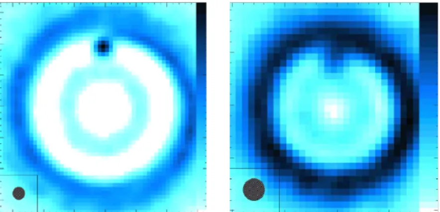
Fig. 1-4 Simulation of ALMA observations of disk at 0.9 THz with an embedded planet of 1Mjup
around a 0.5M⊙ star (orbital radius: 5AU). The assumed distance is 50 pc (left) / 100 pc (right). The
disk mass amounts to Mdisk = 1.0 × 10⁻² M⊙. The size of the combined beam is symbolized in the
lower left edge of each image. Note the reproduced shape of the spiral wave near the planet and the slightly shadowed region behind the planet in the left images. The images are from [11].
possibility of detecting giant planets that are still embedded in young circumstellar disk ([11] Fig. 1-4). They made the point that the hot region in the proximity of a young planet, along with the gap, could be detected and mapped with the ALMA band 10 in the case of nearby circumstellar disks (d < 100 pc) in approximately face-on orientation by showing dust reemission images of the disks. So far, it has been impossible to resolve such the disk spatially due to a limited spatial resolution. Thus ALMA band 10 will play a crucial role by allowing to trace features in disks which are indicative for various stages of the formation and early evolution of planets in circumstellar disks [12].
1.3.2 ALMA band 10 cartridge receiver
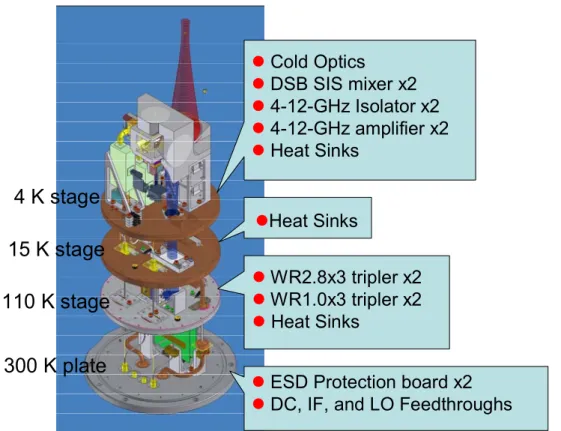
Fig. 1-5 and Fig. 1-6 show a view of the cold optics designed by M. Candotti and the entire prototype band 10 cold cartridge and components, respectively. All of the cartridges are included in a single cryogenic cryostat located on at the cassegrain focus. The beam coming from the telescope passes through the vacuum window and infrared filters. Two ellipsoidal mirrors are used to match the incoming beam and the corrugated feed horn. After reflecting the beam by the pair of the mirrors, the two orthogonal polarizations are split by a free-standing wire grid. Then each beam enters the corresponding feed horn. It should be noted that the optical components consisting of the mirrors, wire grid and feed horns are mounted to the 4-K optics support structure made from one Aluminum block in order to reduce alignment errors.
300 K plate
110 K stage
15 K stage
4 K stage
Cold Optics
DSB SIS mixer x2
4-12-GHz Isolator x2
4-12-GHz amplifier x2
Heat Sinks
Heat Sinks
WR2.8x3 tripler x2
WR1.0x3 tripler x2
Heat Sinks
ESD Protection board x2
DC, IF, and LO Feedthroughs
Fig. 1-6 Schematic view of a prototype cartridge for the ALMA band 10. This was drawn by K. Kaneko.
Table 1-II ALMA band 10 major specifications 1. RF frequency 0.787-0.950 THz 2. Cartridge IF output 4-12 GHz for DSB
3. Cartridge noise performance < 230 K (5hf/kB) (over 80%)
< 344 K (7.5hf/kB) (full band)
4. IF ripple < 4.0 dB/2 GHz, < 6.0 dB/8 GHz 5. Gain compression < 5% between 77 and 373 K 6. Amplitude stability 0.05 and 100 sec < 4.0 x 10⁻⁷
300 sec < 3.0 x 10⁻⁶ 7. Signal path stability < 3 degree/5 minutes 8. RF beam efficiency > 90% at the subreflector 9. Beam squint separation < 10% HPBW on the sky 10. Polarization efficiency > 99.5% (23 dB)
The cartridge receivers of the ALMA band 10 use two Double Sideband (DSB) mixers with orthogonal linear polarizations. Each polarization provides IF bandwidth of 8 GHz centered at 8 GHz (4-12 GHz), which will be achieved by using a 4-12 GHz IF system. The cartridge consists of three cooled stages with operating temperatures of 4 K, 15 K and 110 K, and a room-temperature base-plate which acts as the vacuum seal. The stages are supported by GFPR 10 tubes which have low thermal conductance. LO triplers for generating 300 GHz band (input frequency is the 100 GHz band), heat sinks for the LO waveguides, coaxial cables and wiring, are on the 80 K stage. The only components on the 15 K stage are the heat sinks for the coaxial cables and wiring. The 4 K stage has the mirrors, wire-grid, horns, mixer blocks, isolators, IF amplifiers, and heat sinks for the LO waveguides.
1.3.3 Receiver specification
Major band 10 specifications are listed in Table 1-II.Especially, band 10 requires receivers with a DSB noise temperature below 230 K (5hf/kB) for 80% bandwidth and 344 K (7.5hf/kB) for 100%
bandwidth over the 4–12 GHz intermediate frequency (IF) band at an operating temperature. However, there have been no receivers currently available that satisfy the requirements of both low noise and wideband operation such as the ALMA band 10 specifications as shown in Fig. 1-9.
1.3.4 Other heterodyne Instruments at similar frequency to ALMA band 10.
The Heterodyne Instrument for the Far Infrared (HIFI) of the Herschel Space Observatoryprovides continuous coverage over the range of 0.480 to 0.125 THz in five bands and 1.41 to 1.91 THz in two additional bands at an operating temperature of 2 K (e.g. [15]). HIFI band 3 instrument covers 0.80.96 THz [16] , similar frequency range to the ALMA Band 10. The primary mirror is 3.5-m diameter which is the largest satellite mirror to date. The Herschel spacecraft with HIFI onboard has been launched successfully 14 May 2009.
The Carbon Heterodyne Array of the MPIfR (CHAMP+) is dual channel heterodyne receiver
array of 7 pixels operating in the 0.60.72 THz and 0.790.95 THz atmospheric windows. In early 2007.CHAMP was installed at the Atacama Pathfinder Experiment (APEX) telescope with a antenna diameter of 12 m on the high altitude site of Llano Chajnantor [13][14].
The Caltech Airborne Submillimeter Interstellar Medium Investigations Receiver (CASIMIR)
is a far-infrared (FIR) and submillimeter, very high-resolution, heterodyne spectrometer [17] installed on Stratospheric Observatory for Infrared Astronomy (SOFIA). The primary mirror is 2.7 m in diameter. It is anticipated SOFIA will eventually achieve a flight rate of up to 160 flights per year, with a lifetime of 20 years [18]. During the initial flights in 2010, CASIMIR will have two bands available, 1.0 and 1.25 THz. Three additional bands will be added with ongoing instrument development, providing frequency coverage from 0.5 THz up to 1.4 THz.
Millimetron planed for launch after 2015 is a large (12m diameter) space observatory for millimeter,
submillimeter and far-infrared observations. High sensitivity and (extremely) high angular resolu-tions are achieved by using a 12m diameter space antenna, either in single-dish mode or as element of a spaceground VLBI system. The instrumentation for the single-dish observing mode consists of the two heterodyne instruments HET-1 and HET-2 which cover the astrophysically important frequencies 0.55 and 1.1 THz, 1.9, 2.7 and 4.7 THz, but not including 0.9 THz [19].
1.4 Heterodyne receiver
In the region from millimeter to terahertz wave, electric pre-amplification of weak signals is not yet possible and heterodyne process. For this reason, the low-noise heterodyne mixer is used to downconvert weak RF signals fRF to IF ones fIF by modulating a large LO signal fLO. As shown in Fig.
1-7, incoming signal from space is collected by the optics and coupled with the LO signal. The RF signal is down-converted to IF signal by the mixer. After that, the IF signal is amplified the low noise amplifier. In this case, the downconverted IF signal composed of the two frequencies:
IF LO
RF f f
f .
1-1
Band 10 cartridges detect both sidebands without sideband separation, so-called, Double Sideband (DSB) receiver.
A feature of heterodyne receiver is to allow coherent detection of incoming signal, because
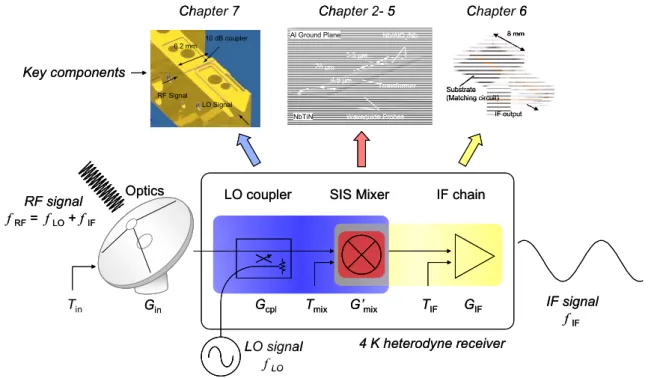
Substrate (Matching circuit) 8 mm IF output SIS Mixer Chapter 2- 5 Tin Gin Tmix G’mix TIF GIF RF signal fRF= fLO+ fIF IF signal fIF IF chain Gcpl LO signal fLO Chapter 7 Chapter 6 LO coupler 10 dB coupler RF Signal 6.2 mm LO Signal Nb/AlOx/Nb 28 µm 4.5 µm Al Ground Plane NbTiN 5.5 µm Transformer Waveguide Probes Optics 4 K heterodyne receiver Key components Substrate (Matching circuit) 8 mm IF output Substrate (Matching circuit) 8 mm IF output SIS Mixer Chapter 2- 5 Tin Gin Tmix G’mix TIF GIF RF signal fRF= fLO+ fIF IF signal fIF IF chain Gcpl LO signal fLO Chapter 7 Chapter 6 LO coupler 10 dB coupler RF Signal 6.2 mm LO Signal 10 dB coupler RF Signal 6.2 mm LO Signal Nb/AlOx/Nb 28 µm 4.5 µm Al Ground Plane NbTiN 5.5 µm Transformer Waveguide Probes Nb/AlOx/Nb 28 µm 4.5 µm Al Ground Plane NbTiN 5.5 µm Transformer Waveguide Probes Optics 4 K heterodyne receiver Key components
Fig. 1-7 Schematic block diagram of a typical heterodyne receiver and key components described in this thesis.
mixing element preserves phase information. Then telescopes incorporating the heterodyne receiver can be used as elements in interferometers, which achieve high spatial resolution required for ALMA. Another is to obtain very high spectral resolution (up to ~ 107 for ALMA receiver, corresponding to Doppler velocities of 0.03 km/s). This is important in that atomic and molecular lines can be observed to study the constituents and dynamics of the gas [3]. Meanwhile, it is well-known that signal-to-noise ratio for a spectrum detected by heterodyne receiver is proportional to a square root of the product of integration time and simultaneous bandwidth, and inverse proportional to the system noise temperature. Since it can not be increased by enlarging the bandwidth for spectral line detections, it is essentially important to reduce the noise temperature. Besides, to measure the chemical properties of the disk, the receiver also needs a wide IF bandwidth, capable of simulta-neously measuring emission lines from many different atomic or molecular species. The wide IF bandwidth would be important when continuum spectrum feature from dust is observed as well.
1.4.1 SIS quasi-particle mixers
SIS quasiparticle mixers are widely used for applications of the radio astronomy and planetary atmosphere taking the low noise performance approaching quantum limit. A waveguide SIS mixer consist of input waveguides, an antenna probe doubled with transition to microstrip mode, tuning circuits and SIS junctions (see Fig. 1-8). The SIS junction has a sandwiched structure of two superconductors separated by very thin insulator layer (~ 5 nm) and then has large geometric capacitance which can shunt the RF signal. Thus the tuning circuits are employed for tuning out the junction capacitance and matching the junction impedance to the antenna impedance.
The SIS mixer relies on an extremely nonlinear I-V characteristic of the SIS junction. The
cur-rent flow mechanism in the case injected microwave electromagnetic radiation is based on the photon-assisted tunneling process discovered by Day and Martin in the early 1960s [20]. The first receivers using this effect were developed by groups at Bell Laboratories, and the California Institute of Technology [21], and the University of California at Berkeley [22].
Unlike direct detection, in heterodyne detection mode, the Heisenberg uncertainty principle puts a limit to the mixer noise temperature, the quantum limit being
B
k hf
TQ . 1-2
This derives from following things. If one measures the energy E of a system and the precise time t
at which the system possesses this energy, the uncertainties in these quantities are related by 2
/ Δ
ΔE t . 1-3
This leads to the equation 2 / 1 Δ
Δn , 1-4
signal . Thus one can not measure both amplitude and the phase of a sinusoidal signal precisely. So far, the high sensitivities for the SIS mixers has been demonstrated that fell close to the quantum limit for frequencies up to 0.7 THz at least and within a factor of ten of this limit up to 1 THz. This would be the greatest merit of using SIS mixers compared to other superconducting heterodyne mixers, such as the Hot Electron Bolometer (HEB) and Josephson effect mixer. The detailed noise property of SIS mixers will be described in later chapter as based on the theory by Tucker and Feldman [23][24].
1.4.2 Receiver sensitivity
In general, the heterodyne receiver sensitivity may be represented by the equivalent input receiver noise temperature
1 1 1 0 0 RX N k k l l k G T T T , 1-5which is known as Friis’ formula, where Tk, and Gl are kth equivalent input noise temperature and lth
(= k-1) available power gain. A passive component with the gain G of less than 1 generates the noise
Waveguide Indium Contact RF+LO signal IF signal WG to Microstrip Transition Al wire NbTiN transformer tuner
wave guide probes
Al wire NbTiN
transformer
tuner
wave guide probes
Bonding Wire IF substrate IF Signal RF+LO Signal 200 m 5 m
Tuning circuit SIS junctions Waveguide to microstrip transition Waveguide IF circuit RF+LO signal IF signal Tmix, Gmix Ttune, Gtune TWG, GWG Back-piece
Magnet Main body
Horn
20 mm
Fig. 1-8 Photograph and block diagram showing composition of an SIS mixer. TWG, GWG, Ttune,
Gtune, Tmix and Gmix, are the equivalent input noise temperatures and the power available gains of the
temperature related to ambient temperature Tamb: amb Att 1 1 T G T . 1-6
Thus the equivalent input receiver noise temperature shown in Fig. 1-7 can be described by
mix cpl in IF cpl in mix in RX G G G' T G G T T T , 1-7
where TIF (10 K), Tmix (100 K) and Tin (15 K) are respectively the equivalent input noise
temperatures of the IF chain, the SIS mixer, and the optics, and G’mix, Gcpl and Gin (< 1) are
respectively the available power gains of the SIS mixer, the LO coupler, and the optics. Gtune and
GWG would not be negligible at the band 10 frequencies, although Ttune and TWG should be less than 1
K. These Gtune (~1.5 dB) and GWG (0.5 dB/10 mm) are one of the parameters making it difficult to
achieve high sensitivity receiver performances in this frequency range, compared to ones in lower frequencies, because the lossless all-Nb circuits are not available and waveguide losses are significantly higher. Therefore, the total receiver noise temperature is given by
mix cpl tune WG in IF cpl tune WG in mix in RX G G G G G T G G G G T T T . 1-8
In conclusion, it is essentially important to reduce Tmix and to make all the gains Gin, GWG, Gtune, Gcpl,
and Gmix as high as possible.
1.5 Key technologies and problems
In this section, key technologies and the problem are overviewed. Thus far, except for the at-mospheric absorption, a cause that has made astronomical observation difficult was degradation of the receiver sensitivity. Fig. 1-9 shows state-of-the-art sensitivity results of receivers developed in some laboratories and also shown is sensitivity goals for ALMA receivers at the operating tempera-ture of 4 K. The data are summarized by Kerr et al [25] and are updated based on refs. [26]-[29]. It can be seen that the receiver noise temperature above 0.7 THz increases rapidly. This is caused by degradation of noise performance of the SIS mixers due to Nb gap frequency as described later. In addition, this may imply that technologies to develop high sensitivity receivers have not been established yet in this frequency range. This is because there have been many technical difficulties, such as development of small waveguide component and low-noise and wideband IF chain.
1.5.1 Low noise and wideband SIS mixers
Noise performance
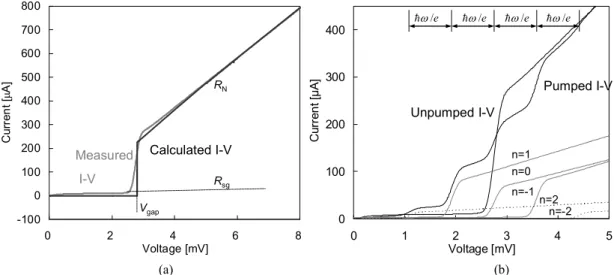
In this frequency range, well-established all-Nb SIS mixers can not be used because RF losses in their microstrip tuning circuits increase significantly as a result of the onset of pair-breaking above the Nb gap frequency of 0.7 THz. For example, RF signals are attenuated by more than 60 % per the wavelength in this frequency range as shown in Fig. 1-10 (a). Thus far, a combination of normal metal and a higher gap superconductor, such as NbN or NbTiN, has been successfully used to reduce the circuit losses in the range 0.7–1.3 THz. However, there are no mixers currently available that satisfy the requirements of both low noise and wideband operation such as the ALMA band 10 specifications. In order to improve the mixer performance, it is important not only to establish the low-loss microstrip lines but also to investigate the mixer noise properties of the Nb junctions above its gap frequency where the mixer gain is significantly degraded.
RF bandwidth
The fractional bandwidth of 19 % for the band 10 receivers has to be covered. Since an SIS mixer has a large capacitance, the RF bandwidth might be limited by RC. For this reason, it might
have been believed that the SIS junction’s current density (Jc) is the most important parameter to
make the RF bandwidth wider. In this case, we have to develop high Jc (>20 kA/cm2) SIS junctions
0 200 400 600 800 1000 0 200 400 600 800 1000 1200 9
Receiver noise t
e
mperat
ure (K)
Frequency (GHz)
NAOJ (Nb) NRAO (Nb) IRAM (Nb) SRON (Nb) SRON (NbTiN) Caltech QO (NbTiN)Shottky diode mixer
3h/kB Band 10 8 7 6 5 4 3 Nb gap 700 GHz 0 200 400 600 800 1000 0 200 400 600 800 1000 1200 9
Receiver noise t
e
mperat
ure (K)
Frequency (GHz)
NAOJ (Nb) NRAO (Nb) IRAM (Nb) SRON (Nb) SRON (NbTiN) Caltech QO (NbTiN)Shottky diode mixer
3h/kB Band 10 8 7 6 5 4 3 Nb gap 700 GHz
Fig. 1-9 State of the art results and sensitivity goal of receivers developed in some laboratories. The data are summarized by Kerr et al [25] and are updated based on refs. [26]-[29]
with very thin barrier as shown in Fig. 1-10 (b). However, it is difficult to obtain such high current density keeping the junction quality. A study of the fabrication using new barrier, such as Aluminum Nitride, would be considered as a candidate to solve the problem.
1.5.2 Wideband IF chain of 4-12 GHz
Another reason which has degraded the receiver sensitivity is IF noise performance, because it is difficult to obtain high mixer conversion efficiency (–5 ~ –10 dB) in the range of this frequency. In our analysis, IF noise temperature accounts for about 20–30 % of the receiver noise temperature. For this reason the IF noise temperature and mixer gain should be kept below 10 K and as high as possible over 4-12 GHz, respectively. However, it is very difficult to achieve the bandwidth beyond 1 octave, keeping such a performance. Although SIS mixers with the high dynamic resistance is allowed to obtain the intrinsic high mixer gain, this has difficulties to match the output impedance of the SIS mixer into 50 network and may result in occurrence of the ripple structure for IF characteristics due to standing wave or oscillation. In addition, this problem makes it hard to achieve the specification that has to be the IF flatness within 4.0 dB per any 2 GHz, and 6.0 dB per any 8 GHz. 0 0.2 0.4 0.6 0.8 1 0.2 0.4 0.6 0.8 1.0 1.2 1.4 1.6 Frequency [THz] Tr an sm is si o n Band 10 Nb/SiO2/Nb NbTiN/SiO2/Al 0 0.2 0.4 0.6 0.8 1 0.2 0.4 0.6 0.8 1.0 1.2 1.4 1.6 Frequency [THz] Tr an sm is si o n Band 10 Nb/SiO2/Nb NbTiN/SiO2/Al 0 5 10 15 20 25 0 5 10 15 20 25
Current density [kA/cm2]
f /Δ f [% ] (a) (b)
Fig. 1-10 Technological problem of SIS mixers for the ALMA band 10. (a) Transmission characte-ristics of superconducting microstrip lines per the wavelength as a function of frequency and (b) Fractional bandwidth versus junction’s current density. At the band 10 frequencies, well-established all-Nb SIS mixers can not be used because RF losses in their microstrip tuning circuits increase significantly as a result of the onset of pair-breaking above the Nb gap frequency of 0.7 THz.
1.5.3 Low loss waveguide components and efficient usage of LO Power
Fig. 1-11 (b) shows calculated losses of the gold-plated rectangular waveguide with the sizes of WR-10 to WR-1.2. The waveguide length is 30 mm, which is typical one for modular type waveguide components. At the band 10 frequencies, very small waveguide with the size of 152 m304 m (WR-1.2) has to be used. The waveguide has very large losses to be 1.2-1.4 dB, compared to that of low frequency. The losses allow noise temperature to be increased by 30-40 %. Therefore, the modular type of waveguide component is no longer available due to the RF losses. In addition, such small waveguide component needs high accuracy fabrication within 5 m at a circuit part and 10 m at a flange part. Thus, we must consider the circuit so as to simplify the fabrication or another scheme.
An advantage of using the SIS mixers is the very modest LO power requirement compared to Shottky diodes. However, in this frequency band close to 1 THz, a lack of local oscillator (LO) power has been a significant issue as shown in Fig. 1-11 (b). The ALMA requires an LO source with no mechanical tuners. Thus, the LO system must consist of electrically-tunable component as based on solid-state devices. Although the high power output devices for terahertz region have been studied, the output power of the sources rapidly diminish at higher frequency (~ 20 W at 0.9 THz, typically) due to the terahertz gap. For this reason we would have to come up with some kind of method to propagate the limited LO power to the SIS mixer.
0 0.2 0.4 0.6 0.8 1 1.2 1.4 0 0.2 0.4 0.6 0.8 1 Frequency [THz] Wav egu id e l oss [ dB /30 m m ] WR-1.2 WR-1.4 WR-6 WR-10 WR-3.7 WR-5 WR-2 WR-3 (a) (b)
Fig. 1-11 Problems of waveguide losses and LO power in terahertz bands. (a) Comparison of gold-plated rectangular waveguide (TE10 mode) losses used in Band 3 to 10 at a temperature of 4 K.
The calculation is based on consideration in section 7.2.1 and assumed to be 30 mm for the length of the waveguide, which is typical one for modular type waveguide components. The waveguide size is based on Virginia Diodes Inc. (VDI) waveguide band designations. (b) THz-emission power as a function of frequency. Solid lines are for the conventional THz sources. This figure is from [30].
1.6 Overview of this thesis
Table 1-III shows the estimated budget of the band 10 receiver noise temperature. In order to achieve the noise temperature of 230 K, all the components have to accomplishment the state of the art performance. This needs to be verified by measurement of the whole cartridge since the loss and Table 1-III Noise budget of the band 10 receiver. The color indicates key components to achieve the specification of 230 K, which are described in this thesis.
Temp. [K] Gain [dB] Input noise [K] Noise at Rec. Input [K] Window 300 -0.1 6 6.3 IR filter 110 -0.2 5 5.0
Cold optics 4 -0.2 1 1.1 5% Loss at 4 K Waveguide 4 -0.5 1 1.1 10 dB coupler 10 dB Coupler 4 -0.5 5 6.3 10 K/μW Tuning circuit 4 -1.5 1.7 2.3 NbTiN/SiO2/Al
Mixer 4 -4.0 83 165 2 hf/kB at 0.87 Isolator 4 -0.6 2.4 12
1st amplifier 4 34 5 29
Cable 150 -2.8 136 0.3 Estimated cable 2nd amplifier 300 28.5 120 1 typical gain Attenuator + Cable 300 -7.1 1239 0.0 Estimated cable
229
Demonstration of wideband and low-noise IF performance
Achievement of the ALMA Band 10 specification Demonstration of low-noise performance
Chapter 3 Chapter 2 Chapter 1
Fundamental theory of heterodyne SIS mixer
Consideration of 412 GHz optimum IF circuit
Waveguide SIS mixers based on epitaxial NbTiN films on MgO substrates
A low-noise waveguide SIS mixer incorporating 10-dB directional coupler Material selection and feasibility study on
SIS mixers for the ALMA band 10 Introduction Chapter 4 Comparison Chapter 6 Chapter 7 Summary Chapter 8 Demonstration of low-noise and wideband performance A low-noise waveguide NbTiN-based
SIS mixer on a quartz substrate Chapter 5
noise listed in Table 1-III. In this thesis, cryogenic devices which contributes to the receiver noise temperature, that is, the waveguide coupler, SIS mixer, and cryogenic IF chain are focused on.
Construction of this thesis is shown in Fig. 1-12. Chapter 2 describes fundamental theory of SIS mixer for modeling the circuit. As based on the theory, chapter 3 provides theoretical verification and feasibility study of material combination for the band 10 SIS mixers, and two microstrip combinations are narrowed down here: epitaxial NbTiN on MgO and poly-crystal NbTiN on quartz. Chapter 4 presents investigation of SIS mixers with Nb junctions and microstrip configuration using epitaxial NbTiN films on MgO and normal metal. On the other hand, chapter 5 deal with SIS mixers with Nb junctions and inverted microstrip lines incorporating poly-crystal NbTiN films on quartz and normal metal. Finally, an SIS mixer satisfying wideband and low noise performances simulta-neously was demonstrated. Chapter 6 describes low-noise IF chains using a state-of-the-art ultra low noise amplifier and a low-loss isolator. In addition, improvements of frequency dependence of IF noise temperature and output power by detailed system consideration including the SIS mixer are described. Chapter 7 presents development of waveguide SIS mixer incorporating LO directional coupler. The insertion loss of the waveguide and coupling factor of the LO coupler were evaluated at both room and cryogenic temperatures. The mixer block was designed on the basis of the characte-rization. Finally, we present the result of achieving ALMA band 10 specification. Chapter 8 summarizes the work described in this thesis.
References
[1] T.G. Phillips, J. Keene, “Submillimeter astronomy [heterodyne spectroscopy],” Proc. of the IEEE 80 (11), 1992.
[2] A. Wootten and A. R. Thompson, “The Atacama Large Millimeter/submillimeter Array,” Proc. of the IEEE 97 (8), 2009.
[3] R. E. Hills, A. J. Beasley, “The Atacama Large Millimeter/submillimeter Array,” Proc. of the SPIE 7012, 2008.
[4] A. B. Peck and A. J. Beasley, “High resolution sub-millimeter imaging with ALMA,” J. Phys.: Conf. Ser. 131, 2008.
[5] R. L. Brown, W. Wild, C. Cunningham, “ALMA – the Atacama large millimeter array,” Advances in Space Research 34, 2004.
[6] L. Testi, “The Atacama Large Millimeter/Submillimeter Array,” Science with the VLT in the ELT Era, Astrophysics and Space Science Proc., ISBN 978-1-4020-9189-6. Springer Nether-lands, 2009.
[7] R.Kurz, S.Guilloteau, P.Shaver, “The Atacama Large Millimetre Array,” The Messenger 107, 2002.
[8] ALMA Construction Project Book, 2002, [Online]. Available: http://www.alma.nrao.edu/projectbk/construction/
[9] S. Iguchi, K. Morita, M. Sugimoto, B. V. VilarÓ, M. Saito, T. Hasegawa, R. Kawabe, K. Tatematsu, S. Sakamoto, H. Kiuchi, S. K. Okumura, G. Kosugi, J. Inatani, S. Takakuwa, D. Iono, T. Kamazaki, R. Ogasawara, and M. Ishiguro, “The Atacama Compact Array (ACA),” Publ. Astron. Soc. Japan 61, 2009.
[10] A. W. Blain, I. Smail, R. J. Ivison, J.-P. Kneib, D. T. Frayer, “Submillimeter Galaxies,” Physics Reports 369 (2), 1992.
[11] S. Wolf and G. D'Angelo, “On the Observability of Giant Protoplanets in Circumstellar Disks,” Astrophys. J. 619, 2005.
[12] S. Wolf, “Detecting protoplanets with ALMA,” Astrophys Space Sci. 313, 2008.
[13] C. Kasemann, S. Heyminck, A. Bell, A. Belloche, C. Castenholz, R.Güsten, H. Hafok, A.Henseler, S. Hochgürtel, B. Klein, T. Klein, I. Krämer, A. Korn, K. Meyer, D. Muders, F. Pacek, F. Schäfer, G. Schneider, G. Wieching, H-J. Wunsch, A. Baryshev, R. Hesper, T. Zijlstra, C.F.J. Lodewijk, T.M. Klapwijk, “CHAMP+: A powerful submm Heterodyne Array,” Proc. 19th Int. Symp. on Space THz Technology, Groningen, 28-30 Apr. 2008.
[14] R. Güsten, A. Baryshev, A. Bell, A. Belloche, U. Graf, H. Hafok, S. Heyminck, S. Hochgürtel, C.E. Honingh, K. Jacobs, C. Kasemann, B. Klein, T. Klein, A. Korn, I. Krämer, C. Leinz, A. Lundgren, K.M. Menten, K. Meyer, D. Muders, F. Pacek, D. Rabanus, F. Schäfer, P. Schilke, G. Schneider, J.Stutzki, G. Wieching, A. Wunsch, F. Wyrowski, “Submillimeter Heterodyne Ar-rays for APEX,” Proc. SPIE. 7020, 2008.
[15] P. Dieleman, D. Teyssier, T. Klein, J. C. Pearson, W. Jellema, J. W. Kooi, J. Braine, P. W. Morris, A. R.W. de Jonge, R. Haan, W. M. Laauwen, H. P. Smit, N. D. Whyborn, P. R. Roelf-sema, F. P. Helmich, and T. W.M de Graauw, on behalf of the HIFI team, “Performance of HIFI in flight conditions,” Proc. 20th Int. Symp. on Space THz Technology, Charlottesville, 20-22 Apr. 2009.
[16] B. D. Jackson, G. de Lange, T. Zijlstra, M. Kroug, J. W. Kooi, J. A. Stern, and T. M. Klapwijk, “Low-Noise 0.8–0.96- and 0.96–1.12-THz Superconductor–Insulator–Superconductor Mixers for the Herschel Space Observatory,” IEEE Trans. Microwave Theory Tech. 54 (2), 2006. [17] D. Miller, M. L. Edgar, A. Karpov, S. Lin, S. J. E. Radford, F. Rice, J. Zmuidzinas, and A. I.
Harris, “CASIMIR – Caltech Airborne Submillimeter Interstellar Medium Investigations Re-ceiver,” proc. 19th Int. Symp. on Space THz Technology, Groningen, 28-30 Apr. 2008.
[18] E. E. Becklin and R. D. Gehrz “Stratospheric Observatory for Infrared Astronomy approaches first light,” SPIE Newsroom 6 Oct. 2009.
[19] W. Wild, A. Baryshev, T. Graauw, N. Kardashev, S. Likhachev, G. Goltsman, V. Koshelets, “Instrumentation for Millimetron - a large space antenna for THz astronomy,” Proc. 19th Int. Symp. on Space THz Technology, Groningen, 28-30 Apr. 2008.
[20] A. H. Dayem and R. J. Martin, “Quantum Interaction of Microwave Radiation with Tunneling Between Superconductors,” Phys. Rev. Lett. 8 (6), 1962
[21] G. J. Dolan, T. G. Phillips, and D. P. Woody, “Low-noise 115-GHz mixing in superconducting oxide-barrier tunnel junctions,” Appl. Phys. Lett. 34, 1979.
[22] P. L. Richards and T. M. Shen, R. E. Harris and F. L. Lloyd, “Quasiparticle heterodyne mixing in SIS tunnel junctions,” Appl. Phys. Lett. 34, 1979.
[23] J. R. Tucker, “Quantum limited detection in tunnel junction mixers,” IEEE J.Quantum Electron. 15 (11), 1979.
[24] J. R. Tucker and M. J. Feldman, “Quantum detection at millimeter wavelengths,” Rev. Mod. Phys. 57, 1985.
[25] A. Kerr, S.-K. Pan, J. Webber, “MMA Receivers: SIS Mixers,” MMA project book, April,1999 http://www.tuc.nrao.edu/~demerson/project_book/chap5/chap5.3/chap5.3.html
[26] W. Shan, S. Asayama, M. Kamikura, T. Noguchi, S. Shi and Y. Sekimoto, “A 385-500 GHz Low Noise Superconductor-Insulator-Superconductor Mixer for ALMA Band 8,” IEICE Trans. on Electron. E89-C (2), 2006.
[27] A. M. Baryshev, F. P. Mena, R. Hesper, T. Zijlstra, C. F. J. Lodewijk, W. Wild and T. M. Klapwijk, “A waveguide NbTiN SIS mixer for THz Array Applications,” Proc. Int. J. Infrared and Millimeter Waves-THz 2006, Shanghai, China, Sep. 2006.
[28] W. Shan, S. Shi, T. Matsunaga, M. Takizawa, A. Endo, T. Noguchi, and Y. Uzawa, “Design and Development of SIS Mixers for ALMA Band 10,” IEEE Trans. Appl. Supercond. 17 (2), 2007 [29] C. F. J. Lodewijk, E. van Zeijl, T. Zijlstra, D. N. Loudkov, F. P. Mena, A. M. Baryshev, and T.
M. Klapwijk, “Bandwidth of Nb/AlN/Nb SIS Mixers Suitable for Frequencies around 700 GHz,” Proc.19th Int. Symp. on Space THz Technology, Groningen, 28-30 Apr. 2008
Chapter 2
Fundamental theory of heterodyne SIS mixer
2.1 Overview
In this chapter, fundamental principles of mixing with quasi-particle tunneling and supercon-ducting transmission line are summarized. Tmix and Gmix in eq. 1-7 are determined by the embedding
circuits and the SIS junction properties: nonlinearity and leakage current of the I-V curve. Tucker and Feldman established the theory of mixing with quasi-particle tunneling by combining the general diode mixing theory with the quantum theory [1]. It is summarized in section 2.2. Besides, it is important to characterize losses Gtune in the tuning circuit, because the input loss not only
increases the receiver noise temperature entirely but also forces the apparent bandwidth of noise temperature narrower. Fundamental principle of the transmission line using superconducting materials is summarized in section 2.3 on the basis of Mattis-Bardeen theory [2].
2.2 SIS junction as a mixing element
Mixing properties of SIS junction are determined by the nonlinear current-voltage characteris-tics and the embedding circuits. Since the SIS mixer is nonlinear circuit, we require a formulation of the nonlinear circuit that relates the small-signal voltages and currents at the harmonic sidebands in order to analysis the SIS mixer performance. Then the SIS junction can be treated as a linear transadmittance. The transadmittance relates voltage at each port to current at each port (e.g. voltage at RF port to current at IF port). The vehicle for this transformation is called a conversion matrix. In nonlinear noise analysis, we must calculate the spectra and correlation properties of those cyclosta-tionary noise sources. The spectra are noise sidebands on each of the harmonics of the large-signal waveform. The correlation properties and transconductance determine the noise and conversion properties [3].
2.2.1 General mixer theory
Although some of the early theoretical work was completely analytical, accurate simulation of practical SIS mixers requires a fully numerical approach. For the practical analysis, in general, there are assumptions that the LO voltage serves only to vary the small-signal SIS junction conductance and capacitance, and that frequency conversion occur via time-varying, small-signal elements. A large signal nonlinear analysis is performed first to determine the junction voltage waveforms. The
small-signal time waveforms for the conductance and susceptance are then found from the junction voltage waveforms. The conversion performance is derived from these, and the set of impedances seen by the junction at each significant mixing frequency, without further consideration of the LO excitation.
When a small-signal voltage is applied to the pumped diode at any one of these frequencies, currents and voltages are generated in and across the junction at all other sideband frequencies. These frequencies are called the small-signal mixing frequencies, m (RF), and are given by the
relation: m 0 m , 2-1 where m = 0, ±1, ±2, ±3 ….
The frequencies are separated from each LO harmonic by an amount equal to the frequency, 0, the
difference between the LO frequency and the RF frequency, usually the IF.
Large signal analysis
The goal of the large-signal analysis is to determine the amplitude VJ of the LO waveforms,
which controls the nonlinear junction current and susceptance, and thereby to determine the small-signal time waveforms for the junction conductance and susceptance. It is assumed that the RF excitation is negligibly small compared to the LO. It is necessary to include the external embedding network. Fig. 2-1 shows a mixer equivalent circuit under LO excitation only. The mixing element is modeled by its large-signal equivalent circuit. The LO is represented by a current generator with
F0 F1 YS1 F2 YS2 F3 YS3 IS1=ILO VJ IJ YS0 IS0=Ib Mixing element LO harmonics Fundamental LO DC bias
Fig. 2-1 Large-signal equivalent circuit of the mixer under LO excitation only. The external circuit is equivalent to set of impedances, the LO embedding impedances, each in series with an ideal series LO filter Fm. Fm has zero impedance at m and infinite impedance at all other frequencies.
amplitude and effective source admittance. The embedding network is equivalent to a set of individual impedances except the mth LO harmonic, m. The mixing element is, therefore, terminated in only one impedance at each LO harmonic. The equations for the circuit at each harmonic give
IsmYsnVjmIjm0, 2-2
where m is the harmonic number. Ism, the source current, is normally zero except for m = 0, 1. Ijm and
Vjm are the frequency-domain current and voltage at the mixing element terminals, respectively. Vjm
is the embedding admittance at the mth harmonic. One practical solution to this problem is to use a type of e.g. harmonic balance [4]. In the case that mixing element is an SIS junction, it is assumed that the higher LO harmonics are short-circuited by the junction capacitance, and then the equation is reduced to the eq. 2-42 in later section.
Small signal analysis
Equation 2-1 defines the mixing frequencies in the time-varying circuit elements, either the conductance or susceptance. At each of these frequencies phasors represent the voltage across the element and the current in it:
Y1 Nonlinear Mixer m=m0 VLO(t) Y2 i2 Y0 i0 Y-1 i-1 i1 …… …… S(t) YS= YL= v0(t)
Fig. 2-2 Schematic diagram of a general heterodyne mixer, with applied LO frequency , signal frequency =S and IF output at . The equivalent embedding networks at all of the sideband
m t jω me m v t v() Re , 2-3
m t jω me m i t i() Re . 2-4These voltage and current components will be linearly related for small signals by an admittance matrix:
m m m m m Y v i . 2-5This Ymm’ indicates conversion matrix, which relates small-signal voltage and current at each port.
The ports are different frequencies at a single set of terminals instead of physically separate ports. Consequently, multiport network theory is directly applicable to the conversion matrix, and such operations as determining voltage gain, input impedance, and conversion to another type of matrix, such as an S-parameter matrix, involve the same relations as conventional multiports. Also, the matrix representation implies that Kirchhoff’s laws must hold for the voltage and current vectors as well as scalar quantities, because sinusoids at different frequencies are linearly independent.
Once the admittance matrix elements Ymm’ relating the small-signal currents and voltages at the
various sideband frequencies have been determined, the analysis of mixer performance is straightforward. In general, there may be incoming radiation applied to the mixing element at any of the sideband ports in Fig. 2-2. An arbitrary set of current generators {m} placed at each sideband
port m of the mixer will produce small-signal current and voltage components across the junction
satisfying m m m m m m m m m m m v Y Y v Y i
) ( , . 2-6Inverting these equations, one obtains the signal voltages produced by this arbitrary set of current generators,
m m m m m Z v , 2-7where, in matrix notation,
1 , mm m mm m m Y Y Z . 2-8
In the practical situation, the output voltage at 0 (=IF) may be written in the form
m m m Z v0 00 0 , 2-9where the quantity
00 0 0m Z m/ Z
does not depend upon the output load termination Y0 =YL. This conclusion is obtained by explicitly
performing the matrix inversion in eq. 2-8, and will prove useful in analyzing the noise properties of the mixer. The effect of a current source m at m is thus equivalent at the output to a fictitious
source 0mm of frequency 0, which depends upon the properties of the mixer but not on the value
of Y0 =YL.
In a fundamental heterodyne mixer, the incoming signal may be represented by 1=S at
frequency +0, as illustrated in Fig. 2-2. The total signal power available at the input is therefore
S 2 S
in 8G
P . 2-11
The power that is frequency down-converted and delivered into the output load may be written in the form 2 S 2 01 L 2 0 L out 2 1 2 1 G v G Z P . 2-12
The conversion efficiency of the mixer in single sideband is then given by
2 01 L S in out SSB mix, P 4G G Z P G . 2-13
In these expressions, the conductances GS and GL represent the real parts of the source and load
admittances YS and YL, respectively. The conversion efficiency is therefore readily calculated in
terms of the small-signal admittance matrix Ymm’ and the terminations Ym of the mixer element at
each of the sideband frequencies. The double sideband (DSB) gain of the mixer can be expressed as Gmix,DSB 2GL(GSZ01 2GI Z012). 2-14
Noise properties
The electronic noise we treat here is a stationary random process. This is that the noise voltage or current at any point in a circuit varies randomly, but with statistical characteristics that do not change with time. The major noise sources in diodes are thermal noise and shot noise.
Shot noise
Shot noise is generated by a random process that each electron probabilistically passes through the junction which creates potential barrier. The shot noise may be analyzed by placing a noise generator I(t) = [I(t)<I(t)>] in parallel with an idealized noiseless mixer, where I(t) is the induced LO current through the intrinsic device and <I(t)> is its expectation.
When the LO voltage is applied, the shot noise is modulated at the LO frequency. Each shot noise component at each missing frequency is converted to the other missing frequencies by the LO fundamental and its harmonics. The noise components at any mixing frequency therefore include up- and down-converted components from each other mixing frequency. Once they are converted to the
IF frequency, those components are correlated.
As with the small-signal analysis, the noise currents in the diode junction at each mixing fre-quency can be expressed via a vector:
N N N I I I I I s 0 s 1 s s s] [ 2-15
where IsN are the shot noise currents at each mixing frequency m. The goal is to find the IF output
voltage due to these noise sources, each of which may be considered as an input noise source at each mixing frequency. The voltage across the junction at mixing frequency m due to shot noise is
] [ ] [ ] [Vsm Zm Is 2-16
where [Zm] is the row of the conversion matrix. The mean-square value of the junction noise voltage
is t † t † s s 2 sm [Zm] [I ] [I ] [Zm] V 2-17
where †t represents the conjugate transpose of the matrix. The term [Is][Is]†t is a matrix
representing the correlations between the shot noise components at the various mixing frequencies. It is, therefore, called the correlation matrix [Cs] for the pumped mixer. The term in this matrix have
been evaluated and are
B eI C I I mn mn [ ] [ ]†t s 2 s s 2-18
where Im-n is the coefficient for the m-n th harmonic in the Fourier series representation of the local
oscillator current.
Noiseless mixing element
Ze
it is
Fig. 2-3 Intrinsic and external noise equivalent circuit of the mixing element The thermal noise source converted to a current source via Thevenin’s theorem
Thermal noise
The other noise source of interest is thermal noise which arises from the random agitation of electrons and is related to black-body radiation with a temperature. Although the noise is treated as a voltage source, it can be converted to a current source via Thevenin’s theorem (see Fig. 2-3), that is, the magnitude of the thermal noise current source is
1 4 / 2 t kT e BG i , 2-19
where T, B, and is the physical temperature of the blackbody, the bandwidth, and angular frequency. Also G is the conductance of embedding circuit. Since the thermal noise arises in G, which does not vary with LO excitation, its components at different frequencies have no correlation, and the correlation matrix is simply a diagonal. Therefore, the correlation matrix for the thermal noise is n m n m e BG C kT m mn 0 1 4 / t , 2-20
where Gm is the real part of the embedding impedance.
Total noise
The voltage at an IF frequency of 0 is the sum of the shot noise and thermal noise components:
†t ] [ ] [ 0 s t 0 2 0 Z C C Z V 2-21Total noise power referred to the input port using this output voltage and eq. 2-16 is given by
) Re( 1 2 01 2 0 total Y Z V P . 2-22
Therefore the equivalent input mixer noise temperature can be characterized by defining the noise current source 4kTmixBRe(Y1) connected in parallel with an idealized noiseless mixer