45
The Bulletin of Institute of Technologists, No. 1
論 文 Article
微破壊試験に及ぼすコンクリートの高さ方向による測定箇所の影響
原稿受付 2010 年 4 月 21 日 ものつくり大学紀要 第 1 号 (2010) 45~49後藤正明
*1,澤本武博
*2,因幡芳樹
*3,守屋健一
*3 *1 ものつくり大学大学院 ものつくり学研究科 大学院生 *2 ものつくり大学 技能工芸学部 建設技能工芸学科 *3 株式会社フローリック 東日本技術センターEffect of Measurement Part by Height of Concrete Member
on Compressive Strength and Semi-Destructive Testing.
Masaaki GOTO*1, Takehiro SAWAMOTO*2, Yoshiki INABA*3 and Kenichi MORIYA*3
*1
Graduate student. Graduate school of Technologists, Institute of Technologists *2
Dept. of Building Technologists, Institute of Technologists *3
FLOWRIC Eastern Japan Technical Center
Abstract The properties of concrete such as compressive strength and durability are affected by height of the member
and they are widely known. However, correlation between measurement point of the member and result of semi-destructive testing is not obvious. In this study, the effects of measurement point by height of 800mm concrete member on semi-destructive testing such as rebound number and scratch width were investigated. The main conclusion are as follows. (1) In case height of concrete member was 800mm, the lower the measurement point of the concrete member, the heavier the bulk density of concrete. However, the compressive strength became smaller. (2) The height of the measurement point could hardly affected the rebound number. (3) The higher the measurement point, the more wide the scratch became. (4) The rebound number and depth of chloride penetration shown durability of concrete were mutually correlated.
Key Words : Concrete, Semi-destructive testing, Rebound number, Scratch width
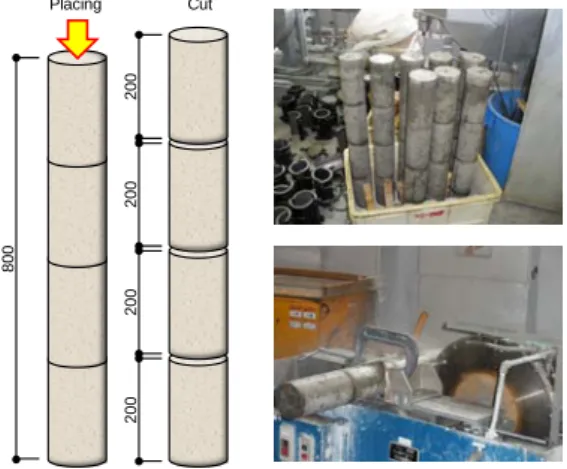
46 微破壊試験に及ぼすコンクリートの高さ方向による測定箇所の影響 率:2.89,吸水率:1.86%)を,粗骨材には東京都 青梅市産砕石(密度:2.70g/cm3,実積率:59.6%, 吸水率:0.40%)を用いた.また,混和剤には AE 減水剤を用いた.コンクリートの配合は,水セメ ント比を変化させた 4 種類とした.フレッシュコ ンクリートの試験結果も併せて表 1 に示す.なお, コンクリートの練混ぜは,公称容量 55 リットルの 強制二軸ミキサで行い,1 バッチ 50 リットルの練 混ぜ量で 2 バッチ作製し,混合して試料とした. 2.2 供試体の作製 実験に用いた型枠は,φ100×800mm の円柱で あり,直径 100mm の開口部から 2 層に分けてコ ンクリートを打ち込んだ.なお,各層内部振動機 を使用する場合はそれぞれ 15 秒ずつ,突棒を使用 する場合はそれぞれ 20 回ずつの締固めを行った. その後,材齢 7 日で脱型,図 1 に示したようにφ 100×200mm の寸法に切断し,材齢 28 日まで 20℃・相対湿度 60%の環境下で気中養生を行った. 2.3 各種試験および測定方法 2.3.1 反発度試験 耐圧試験機で供試体を 2.5N/mm2の力で拘束し1),NR型リバウンドハン マを用いて図 2 の箇所 9 点より,反発度を測定し た. 2.3.2 引っかき傷試験 図 2 に示すように, 引っかき試験器を供試体に押し当て,3 点の引っ かき傷幅を測定した.なお,引っかき傷幅はクラ ックスケールおよびフラッシュルーペを用いて測 定した2,3). 2.3.3 圧 縮 強 度 試 験 試 験 機 は JIS B 7721:2002 の規定を満たす試験機を使用し,圧縮 強度試験は JIS A 1108:2006 に準じて行った.な お,試験時供試体の端面処理は研磨により行った. 2.3.4 塩分浸透深さ試験 実験では,材齢 7 日で脱型した供試体を,NaCl 濃度 10%の塩水中 に 28 日間浸漬した.その後,φ100×200mm の円 柱供試体を,コンクリートの引張試験と同様の方 法で割裂し,その割裂面(100×200mm)に,JIS K 8550:2006 に規定する硝酸銀 17g を純水に溶かし て 1 リットルとした 0.1mol/ℓ の硝酸銀溶液を適量 噴霧し,一定時間暗室に静置した後,発色傾向を 観察,その幅を測定した4).
Fig. 2 Measurement point
100 100 20 20 Scratch line Measure point 100 30 30 Blow point 100
Rebound test Scratch test
Table 1 Mix proportions and test results
Compressive strength W C S1* S2* G Ad Slump (cm) Air content (%) Bleeding in percent (%) 28 days (N/mm2) 45.0 44.2 166 369 392 385 1013 C×1.0% 12.0 4.0 3.45 54.4 55.0 46.0 166 302 421 416 1013 C×1.0% 13.0 4.8 4.38 42.9 61.9 50.0 187 302 443 438 910 C×1.0% 21.0 4.5 6.04 31.6 71.0 52.0 187 263 468 463 888 C×1.0% 20.5 4.5 10.16 20.8
* S1:Product of Kimitsu S2:Product of Kamisato 4.5
±1.5
Unit content (kg/m3) Test result
W/C (%) s/a (%) Air content (%)
47
The Bulletin of Institute of Technologists, No. 1
0 100 200 300 400 500 600 700 800 2250 2300 2350 2400 2450 H ei gh t ( m m) Bulk density (kg/m3) w/c 45% w/c 55% w/c 62% w/c 71% Internal vibrator 0 100 200 300 400 500 600 700 800 20.0 30.0 40.0 50.0 60.0 H ei gh t ( m m) Compressive strength (N/mm2) w/c 45% w/c 55% w/c 62% w/c 71% Internal vibrator 0 100 200 300 400 500 600 700 800 25.0 30.0 35.0 40.0 H ei gh t ( m m) Rebound number w/c 45% w/c 55% w/c 62% w/c 71% Internal vibrator 0 100 200 300 400 500 600 700 800 2250 2300 2350 2400 2450 H ei gh t ( m m) Bulk density (kg/m3) w/c 45% w/c 55% w/c 62% w/c 71% Tamping rod 0 100 200 300 400 500 600 700 800 20.0 30.0 40.0 50.0 60.0 H ei gh t ( m m) Compressive strength (N/mm2) w/c 45% w/c 55% w/c 62% w/c 71% Tamping rod 0 100 200 300 400 500 600 700 800 25.0 30.0 35.0 40.0 H ei gh t ( m m) Rebound number w/c 45% w/c 55% w/c 62% w/c 71% Tamping rod
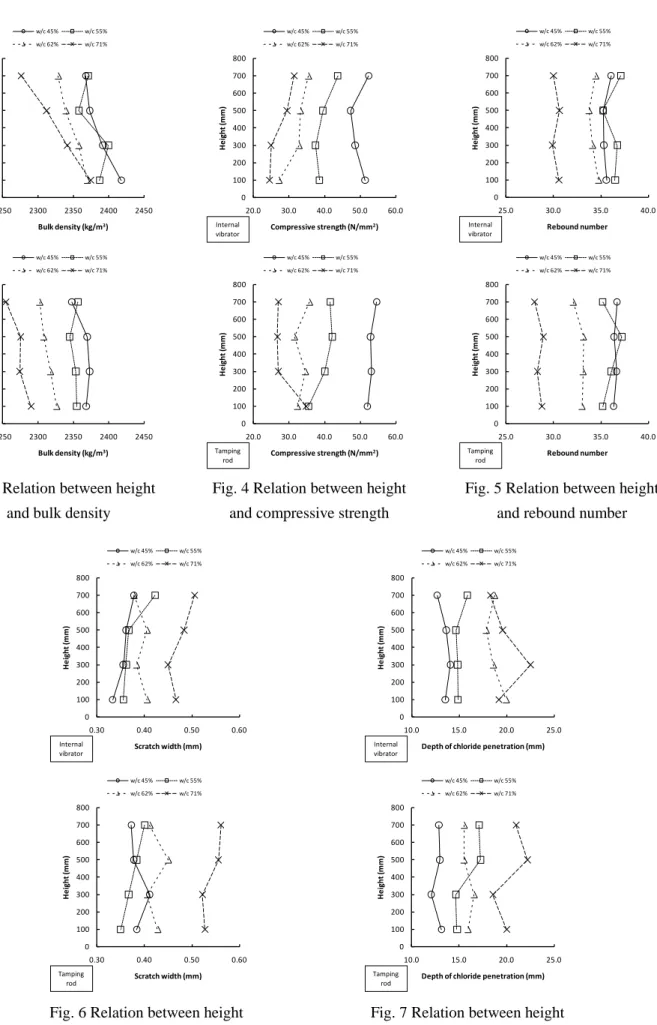
Fig. 3 Relation between height and bulk density
Fig. 4 Relation between height and compressive strength
Fig. 5 Relation between height and rebound number
Fig. 6 Relation between height and scratch width
Fig. 7 Relation between height and depth of chloride penetration 0 100 200 300 400 500 600 700 800 0.30 0.40 0.50 0.60 H ei gh t ( m m) Scratch width (mm) w/c 45% w/c 55% w/c 62% w/c 71% Tamping rod 0 100 200 300 400 500 600 700 800 10.0 15.0 20.0 25.0 H ei gh t ( m m)
Depth of chloride penetration (mm)
w/c 45% w/c 55% w/c 62% w/c 71% Tamping rod 0 100 200 300 400 500 600 700 800 0.30 0.40 0.50 0.60 H ei gh t ( m m) Scratch width (mm) w/c 45% w/c 55% w/c 62% w/c 71% Internal vibrator 0 100 200 300 400 500 600 700 800 10.0 15.0 20.0 25.0 H ei gh t ( m m)
Depth of chloride penetration (mm)
w/c 45% w/c 55% w/c 62% w/c 71%
48 微破壊試験に及ぼすコンクリートの高さ方向による測定箇所の影響
3.実験結果および考察
3.1 密度および圧縮試験結果 図 3 および図 4 に,それぞれ密度および圧縮強 度の試験結果を示す.内部振動機で締固めを行っ た場合,下部ほど密度は大きくなるが,逆に圧縮 強度は小さくなる傾向にあり,水セメント比が大 きい配合ほどその傾向は顕著であった.これは, 水セメント比が大きいほど,内部振動機の締固め によって粗骨材が沈下し,上部がモルタルに近づ くためと考えられる.一般的に上部ほどブリーデ ィングの影響により強度低下し,下部ほど圧密に より強度増加することが知られているが,今回の 実験のように,部材高さが 800mm の場合は,下 部ほど粗骨材量が増加し,付着ひび割れによる強 度低下の方が卓越したようである.一方,突棒で 締め固めた場合は,内部振動機に比べて締固めの 能力が低下するためか,高さ方向の影響は小さく なった. 3.2 反発度および引っかき傷幅試験結果 図 5 に,NR型による反発度の結果を示す.反 発度は高さ方向の影響をほとんど受けず,水セメ ント比の影響のみを受けるという結果となった. これは,粗骨材の付着ひび割れを伴う破壊試験と は異なり,表層の硬さを錘の跳ね返りの高さで測 定するため,骨材量の影響をあまり受けないため と考えられる.しかし,水セメント比が大きい場 合には,圧縮強度よりも締固めの影響を受け,突 棒を用いた時には,反発度が小さくなる傾向にあ った.一方,図 6 に示すように,引っかき試験の 場合は,上部ほど引っかき傷幅が大きくなる傾向 にあり,ブリーディング率の大きい配合ほど顕著 であった.これは,コンクリートのごく表層部を 測定しているため,ブリーディング水の影響を顕 著に受けたためと考えられる.また,反発度の時 と同様に,突棒で締固めた場合には,内部振動機 で締固めた場合に比べ,コンクリートの表層部が 弱くなる傾向にあった.Fig. 8 Relation between compressive strength and rebound number
Fig. 9 Relation between compressive strength and scratch width
y = 2.4x - 44.5 R² = 0.58 20 30 40 50 60 25 30 35 40 Co m pr es si ve st re ng th (N /m m 2) Rebound number y = -95.6x + 77.9 R² = 0.41 20 30 40 50 60 0.3 0.4 0.5 0.6 Co m pr es si ve st re ng th (N /m m 2) Scratch width (mm)
Fig. 10 Relation between depth of chloride penetration and rebound number
Fig. 11 Relation between depth of chloride penetration and scratch width
49
The Bulletin of Institute of Technologists, No. 1