九州大学学術情報リポジトリ
Kyushu University Institutional Repository
初期欠陥を有するRCおよびPC部材の自然環境下にお ける劣化および鋼材腐食に関する研究
アムリ, ダサル
https://doi.org/10.15017/1866287
出版情報:Kyushu University, 2017, 博士(工学), 課程博士 バージョン:
権利関係:
A STUDY ON DETERIORATION AND CORROSION BEHAVIOR OF RC AND PC MEMBERS
WITH INITIAL DEFECTS
UNDER ENVIRONMENTAL ACTION
初期欠陥を有するRCおよびPC部材の自然環境下に おける劣化および鋼材腐食に関する研究
AMRY DASAR
A STUDY ON DETERIORATION AND CORROSION BEHAVIOR OF RC AND PC MEMBERS
WITH INITIAL DEFECTS
UNDER ENVIRONMENTAL ACTION
A DISSERTATION
Submitted to Kyushu University
in partial fulfillment of the requirements for the degree of
Doctor of Engineering
by
AMRY DASAR
DEPARTMENT OF CIVIL AND STRUCTURAL ENGINEERING GRADUATE SCHOOL OF ENGINEERING
KYUSHU UNIVERSITY Fukuoka, Japan
August, 2017
Specially dedicated to
Muhammad Dasar Sewang & Rahmawaty Annas Dahlia Patah
Hikari Azzahramugni Amry
for
the prayers, patience, support, sacrifice, tears and laughter
i
ACKNOWLEDGMENTS
After an intensive period of three years, today is the day: writing this note of thanks is the finishing touch on my dissertation. It has been a period of intense learning for me, not only in the scientific arena, but also on a personal level.
Writing this dissertation has had a big impact on me. I would like to reflect on the people who have supported and helped me so much throughout this period.
I would like to express my special appreciation and sincere gratitude to my supervisor Prof. Hidenori HAMADA, for his patience, motivation, enthusiasm, endless encouragement, immense knowledge and guide throughout my six years of research. He always been available to advise me even he is busy with his daily routine work, make him a great mentor. He inspired me about the art of research in long-term performance. Thank you for your kindness and for accepting me seven years ago to experience your extensive knowledge in Concrete Engineering.
My sincerely gratitude also goes to Advisory Committee, Prof. Shinichi HINO and Prof. Koji TAKEWAKA for their precious suggestions and insightful comments with regard to improve this research work. Thank you also for letting my defense be a memorable moment.
I would also like to address my thanks to Assoc. Prof. Yasutaka SAGAWA for his worth guidance and valuable advices during my research and writing of this dissertation. It may look like small but your humble attitude despite your great knowledge in Concrete Engineering really impressed me.
My thankful also goes to Mr. Daisuke YAMAMOTO for his tremendous help, precious friendship during my study and his non-stop help throughout my experimental work. His wonderful skills really lighten the arising problem.
I acknowledge my gratitude to the Indonesia Endowment Fund for Education (LPDP) for financial support during my study in Japan.
I also want to thanks to Dr. Eng. Rita IRMAWATY for the opportunity and open my vision to study in Japan seven years ago.
I would also like to take this opportunity to express the profound gratitude from my deep heart to my beloved wife, my lovely daughter, my beloved mother
ii
and father, parent-in-law, my brothers and sisters, and brother-in-law, for their love, wise counsel and sympathetic ear, patience and continuous support during my study in Japan. All of you always there for me.
Finally, there are my friends. We were not only able to support each other by deliberating over our problems and findings, but also happily by talking about things other than just our papers.
iii
ABSTRACT
The durability of steel reinforced concrete in chloride environments is of great interest to design engineers, infrastructure owners and maintainers, and researchers. The problem is how to achieve durability through careful design of the cement matrix and its microstructures, and determine the minimum concrete cover for reinforcement that meets the requirements of environmental actions.
Optimal design necessary advances in the knowledge base relevant to the durability of steel reinforced concrete in chloride environments, including: the role of supplementary cementitious materials (SCMs) in concrete durability, the methods of measuring the chloride penetration into concrete, the challenges in assessing concrete durability from its chloride ingress, and design for long-lasting of reinforced concrete in chloride environments. Therefore, the aim of this study is to provide an overview related durability assessment of RC and PC member due to initial defects (crack and chloride) under environmental action. Further, this study will be contributing for necessary information because it provides a demonstration of the long-term behavior of a commonly used construction material, permitting the prediction of the behaviors of existing structures and the more informed design and study of structures to be built. The results of this study may guide engineers in the development of longer-lasting reinforcements for concrete structures.
In Chapter 1, the back ground of this study, research objective, research contribution and standing point. The aim of this study is to provides an overview related durability of RC and PC member due to initial defects (crack and chloride) under environmental action. Further, long-term exposure by field case (i.e., natural corrosion environments) and laboratory case (i.e., artificial corrosion environments) regarding of corrosion behavior and deterioration progress of RC and PC member is one of the advantage from this study. The expected result of this study is to propose an overview assessment regarding durability evaluation of
iv
concrete member embedded steel due to corrosion based on the long-term exposure by field case and laboratory case. Therefore, handling and right countermeasure could be breaking down for the future design of long-lasting performance of RC and PC member.
In Chapter 2, previous study is presented to illustrate the existing body of knowledge that has been established by previous researches. Provide literature regarding role chlorides for the corrosion of reinforcements. The amount chloride for breakdown or initiate corrosion. Further, concrete cracking and the effect to reinforcing bar corrosion. Evaluation report obtained from the long-term performance of RC and PC member. These such literature or evaluation became necessary information in order to provide an appropriate assessment regarding durability of concrete member. The evaluation result will provide necessary information and reference for the future design and construction of long-lasting reinforcements for concrete structures particularly in marine environments.
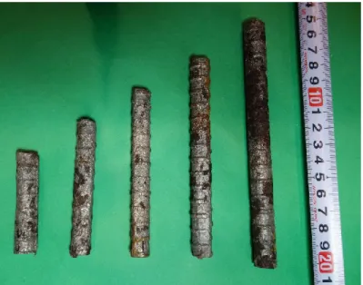
Chapter 3 describes evaluation of deterioration progress and performance reduction of 40-year-old corroded reinforced concrete (RC) beams in natural corrosion environments. The corrosion process was natural, without acceleration by current application, admixture inclusion, or exposure to an artificial chloride environment. In this study, two 40-year-old RC beams, exposed to real marine environments (i.e., tidal and splash zones). The beams are categorized into two conditions in terms of pre-cracking, denoted as A and B. Condition A indicates the presence of pre-cracks (henceforth abbreviated as RC-S-A), while condition B indicates no pre-cracking (henceforth called RC-S-B). The mechanical performance of the beams was evaluated through a four-point bending test. The corroded steel reinforcing bars were extracted for corrosion evaluation and tensile testing. The pre-cracks led to changes in the failure mode of the beams due to extremely degree of corrosion. A good correlation was established between crack width and cross-sectional loss under natural corrosion processes. Each percentage point of cross-sectional loss corresponded to a 2.5% loss in elongation, 1.5% loss in yielding capacity, and 1.3% loss in ultimate capacity. Therefore, for every 1%
of local cross-sectional loss in the tensile steel bars, a 1.0% reduction in the load-
v
carrying capacity of the RC beams occurs. Furthermore, the relationship between deterioration progress and performance degradation with the exposure period for each deterioration stage was elucidated.
Chapter 4 reported in total of seven prestressed concrete beams (PC) were taken out for evaluation, consisted of four beams post-tension type (herein after abbreviated as PC-O) and three beams pre-tension type (PC-R). The beams are categorized into two conditions in terms of pre-cracking, presence of pre-cracks and no pre-cracking. In order to investigate the effect of crack on prestress loss and bending capacity after long-term exposed, prestressed concrete beams were pre-crack and then exposed to marine environment. Experimental work was carried out to evaluate PC beams performance after long-term exposed.
Furthermore, evaluation of prestress loss conducted through four-point loading bending test and the remaining tendon forces in the beam were determined using Crack Re-opening Method. In view point of mechanical properties, the effect of pre-cracked on compressive strength take place. The compressive strength was reduced about 18.35% and 9.43% for PC-O and PC-R beams respectively. While, modulus of elasticity showed a minor differences between with and without pre- cracked. Allowable prestress loss for pre-tensioning and post-tensioning were 25% and 20%, respectively. The total prestress loss for pre-tensioning type for un- cracked and pre-cracked were 22.18% and 38.21%, respectively. Whereas, post- tensioning type for un-cracked and pre-cracked were 23.73% and 48.86%, respectively. Both type PC beam, pre-tensioning and post-tensioning type for pre- cracked condition, over allowable prestress loss already. Further, for un-cracked condition, only post-tensioning type over the allowable prestress loss.
Chapter 5 introduces reinforced concrete prisms with various of crack width and concrete cover. The influencing parameters such as crack width, concrete cover, exposure condition and utilization of SCMs. Therefore, the aim of this study is to understand the effect of crack width, concrete cover and the exposure conditions as well, with associated supplementary cementitious materials by BFS.
Crack width experiencing an influence for a given concrete quality (binder type and w/b ratio) and concrete cover were same. Corrosion rate increased with
vi
increasing crack width particularly in OPC. However, it is suggested that utilization of SCMs (50%BFS), the impact of increasing crack width can be possibility reduced. Corrosion rate decreased with increasing concrete cover for a given concrete quality (binder type and w/b ratio) and crack width were same.
Nevertheless, it is suggested that the corrosion rate in BFS probably were less affected than in OPC. Further, exposure condition more affected particularly in high of chloride environment such 3% NaCl for a given concrete quality (binder type and w/b ratio), concrete cover and crack width were same. However, the influence of differences w/b ratio is not clear. Therefore, it is suggested for any further research with different w/b ratio. It is suggested that BFS cement induced a delay in penetration of chlorides ions compared to OPC cement. In the case of crack exist, BFS has possibility to reduce corrosion of steel bar in the crack portion compared OPC.
Chapter 6 introduces sea-water has potential to be used for mixing water.
The utilization of sea-water in concrete production has potential, regardless of need good care and proper handling. Further, sea-water as mixing water and also utilization supplementary cementitious materials (SCMs) showed different result on corrosion activity. The following possibilities and suggestions for any further research in order to utilize sea-water in proper handling as follows: Both sea- water as mixing and curing water give influence on corrosion activity. It suggested change transition form of steel from passive to initiate of corrosion due to additional chloride ion from sea-water. Therefore, thick of concrete cover was recommend when sea-water is used for mixing. Further, it is suggested that SCMs by BFS decreased the amount of chlorides ions compared to OPC for sea-water mixing. In addition, it is recommended to use corrosion inhibitor of reinforced steel such as epoxy-coated to protect reinforcing steel from corrosion when sea- water is used. Also, reinforcing stainless steel bar as reinforcement also recommended because the critical chloride ion concentration of stainless steel (SUS304-SD) is 15 kg /m3. In fact, both half-cell potential and chloride content over the threshold value, however still not corrosion yet. Therefore, concrete quality such water to cement ratio (w/b) is became important parameter and also it
vii
is suggested oxygen supplies take an important role for corrosion despite of chloride content over the threshold value for breakdown passivity film of steel bar as well.
Chapter 7, the corrosion affected by two phenomena particularly in marine environment, either cracked on concrete surface or chloride attack. Both crack and chloride could exist even from initial (initial defects) or during service life. These two phenomena became important consideration in order to evaluate durability of RC and PC member under environmental action. In the marine environment, the most severity rating zone were tidal and splash zone. In presence of initial cracks accelerated the deterioration progress and performance degradation in RC and PC beams observed compared without initial cracks. Therefore, concrete cover of 30 mm with w/c of 0.68 for RC was not enough for marine structures particularly in tidal and slash zone for service life of 50 years. Further, concrete cover for 30 mm and 40 mm with w/c of 0.37 was not sufficient to protect PC tendons (with sheath and grout cement paste) and PC wires from corrosion, respectively. In addition, a strong correlation was observed between crack width and cross-sectional loss and cross-sectional loss with load-carrying capacity as well under natural corrosion process. For every 1% of local cross-sectional loss in the tensile steel bars, a 1.0%
reduction in the load-carrying capacity of the RC beams occurs. Therefore, it is possible to estimate deterioration progress and performance degradation.
Chapter 8 convey summary, overview of findings and conclusions, and future research work.
viii
TABLE OF CONTENTS
ACKNOWLEDGEMENT i
ABSTRACT iii
TABLE OF CONTENTS viii
LIST OF TABLES xiv
LIST OF FIGURES xvi
CHAPTER
1. GENERAL INTRODUCTION I-1
1.1 Research Background I-1
1.2 Research Objective I-2
1.3 Research Contribution and Standing Point I-2
1.4 Dissertation Outline I-3
References I-5
2. STATE OF THE ART ON CORROSION OF REINFORCING STEEL
BAR II-1
2.1 Introduction II-1
2.2 Corrosion of Steel in Concrete 2.2.1 Corrosion mechanism 2.2.2 Corrosion cell in concrete 2.2.3 Passivation
II-2 II-2 II-5 II-6 2.3 Chloride Induced Corrosion of Steel in Concrete
2.3.1 Roles of chloride
2.3.2 Chloride corrosion threshold 2.3.3 Critical chloride content
II-7 II-8 II-9 II-11 2.4 Fundamentals of Electrochemical Corrosion
2.4.1 Half-cell potential
2.4.2 Anodic-cathodic polarization curve
II-15 II-16 II-18 2.5 Corrosion of steel in cracked concrete
2.5.1 Design codes and technical committees
II-20 II-21
ix
2.5.2 Critical crack width – a review II-22 2.6 Corrosion in Reinforced Concrete (RC) and Prestressed
Concrete (PC)
2.6.1 Reinforced concrete structures on durability view 2.6.2 Prestressed concrete structures on durability view 2.6.3 Long-term exposure in natural corrosion
environments by PARI
II-26
II-26 II-29 II-30
2.7 Issues Addressed in this Study II-32
References II-35
3. DETERIOARATION PROGRESS AND PERFORMANCE REDUCTION OF 40-YEAR-OLD RC BEAM IN NATURAL CORROSION ENVIRONMENTS
3.1 Introduction III-1
3.2 Materials and Methods 3.2.1 Composition 3.2.2 Material Properties 3.2.3 Beam details
3.2.4 Exposure conditions 3.2.5 Loading system
III-3 III-3 III-3 III-4 III-4 III-5 3.3 Experimental Outline
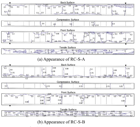
3.3.1 Cracking map
3.3.2 Electrochemical evaluation 3.3.3 Mechanical test
3.3.4 Cross-sectional loss 3.3.5 Tensile test
3.3.6 Chloride ion distribution
III-6 III-6 III-6 III-7 III-7 III-8 III-8 3.4 Experimental Results and Discussion
3.4.1 Deterioration progress of 10-year-old 3.4.2 Deterioration progress of 20-year-old 3.4.3 Deterioration progress of 40-year-old
III-9 III-9 III-10 III-11
x a. Cracking map b. Half-cell potential
c. Mechanical behavior of the beams d. Chloride ion distribution
e. Corrosion distribution of the steel bar f. Cross-sectional loss of the steel bar g. Tensile test
h. Bending test
3.4.4 Progress of deterioration progress
III-11 III-14 III-14 III-16 III-16 III-21 III-22 III-26 III-28
3.5 Conclusions III-33
References III-35
4. THE EFFECT OF PRE-CRACKED ON PRESTRESSED CONCRETE BEAMS UNDER MARINE ENVIRONMENTS
IV-1
4.1 Introduction IV-1
4.2 Experimental Program 4.2.1 Beam details
4.2.2 Exposure conditions
IV-3 IV-3 IV-5 4.3 Test Item and Method
4.3.1 Material testing of beam 4.3.2 Bending test
4.3.3 Evaluation of prestress loss
IV-6 IV-6 IV-7 IV-8 4.4 Experimental Result and Discussion
4.4.1 Appearance of beam
4.4.2 Compressive strength and modulus of elasticity 4.4.3 Pore volume, chloride ion and carbonation depth 4.4.4 Load carrying capacity
a. Decompression load and prestress loss b. Change in flexural moment
4.4.5 Corrosion state of prestressed tendon/wire and steel bars
IV-9 IV-9 IV-11 IV-12 IV-14 IV-14 IV-16 IV-18
xi
4.5 Conclusions IV-19
References IV-21
5. ELECTROCHEMICAL BEHAVIOR OF STEEL IN CRACKED CONCRETE - INFLUENCE OF CRACK WIDTH, COVER, EXPOSURE CONDITION AND SUPPLEMENTARY
CEMENTITIOUS MATERIALS (SCMs)
V-1
5.1 Introduction V-1
5.2 Experimental Procedure 5.2.1 Materials
5.2.2 Mix proportions 5.2.3 Specimen design 5.2.4 Experimental method
V-2 V-2 V-2 V-3 V-5 5.3 Results and Discussion
5.3.1 Half-cell Potential (1) Effect of crack width (2) Effect of concrete cover (3) Effect of curing condition
(4) Effect of supplementary cementitious materials 5.3.2 Anodic Polarization Curve
(1) Effect of crack width (2) Effect of concrete cover (3) Effect of curing condition
(4) Effect of supplementary cementitious materials (5) Summary of anodic polarization curve
5.3.3 Visual Observation and Corrosion Area
V-7 V-7 V-7 V-8 V-9 V-11 V-12 V-12 V-13 V-14 V-14 V-15 V-17
5.4 Conclusions V-18
References V-19
6. LONG-TERM ELECTROCHEMICAL EVALUATION OF STEEL IN SEA-WATER MIXED
VI-1
xii
6.1 Introduction VI-1
6.2 Experimental Program 6.2.1 Materials
6.2.2 Mix Proportions 6.2.3 Specimen Design 6.2.4 Experimental Method
VI-2 VI-2 VI-3 VI-3 VI-7 6.3 Results and Discussion
6.3.1 Half-cell potential plain bar series 6.3.2 Half-cell potential various bar series
6.3.3 Anodic-cathodic polarization curve – plain bar series - Effect of tap-water mixing and curing
- Effect of sea-water mixing and tap-water curing - Effect of tap-water mixing and sea-water curing - Effect of sea-water mixing and curing
6.3.4 Anodic-cathodic polarization curve – plain bar series
- Effect of tap-water mixing and curing
- Effect of sea-water mixing and tap-water curing - Effect of tap-water mixing and sea-water curing - Effect of sea-water mixing and curing
6.3.5 Chloride ion profile 6.3.6 Actual corrosion
VI-8 VI-8 VI-11 VI-15 VI-15 VI-15 VI-16 VI-17 VI-19 VI-19 VI-20 VI-21 VI-21 VI-21 VI-23 VI-24
6.4 Conclusions VI-28
References VI-29
7. AN OVERVIEW FOR DURABILITY ASSESTMENT OF RC AND PC MEMBER DUE TO CORROSION
VII-1
7.1 Introduction VII-1
7.2 Evaluation on chloride ion penetration – experimental result
7.2.1 Artificial chloride environment – NaCl solution
VII-2
VII-2
xiii
7.2.2 Impact of Concrete Cracks on Corrosion VII-5 7.3 Proposal on Estimation of Long-lasting Performance –
Discussions
VII-7
7.4 Summary VII-12
References VII-14
8. CONCLUSION AND FUTURE RESEARCH WORK VIII-1
8.1 Summary VIII-1
8.2 Overview of Findings and Conclusions VIII-2
8.3 Future Research Work VIII-6
xiv
LIST OF TABLES
Table No Page
Table 2.1 Previous studies Ccrit values under outdoor exposure conditions and from real structures.
II-14
Table 2.2 Previous studies Ccrit values under laboratory conditions II-14
Table 2.3 Corrosion probability II-16
Table 2.4 Grade of passivity film associated anodic polarization curve II-19 Table 2.5 Literature of short-term crack width in reinforced concrete
(RC)
II-23
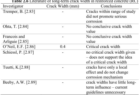
Table 2.6 Literature of long-term crack width in reinforced concrete (RC)
II-24
Table 2.7 Literature of crack width in prestressed concrete (PC) II-25
Table 2.8 Defenition of deterioration stage II-28
Table 3.1 Summary of aggregate III-3
Table 3.2 Mix proportion of concrete III-3
Table 3.3 Summary of RC beam specimens III-6
Table 3.4 Evaluation at 10 years III-9
Table 3.5 Summary of tensile test results III-22
Table 3.6 Summary of bending tests III-26
Table 3.7 Criteria for diagnosis of deterioration degree III-29
Table 3.8 Deterioration degree III-29
Table 3.9 Determination of deterioration progress and performance degradation
III-33
Table 4.1 Summary of aggregates IV-4
Table 4.2 Summary of PC beam specimens IV-6
Table 4.3 Summary of prestressing force loss IV-16
Table 4.4 Summary of several points during loading procedure IV-17
Table 4.5 Summary of corroded area IV-19
Table 5.1 Physical properties V-2
Table 5.2 Mix proportions of concrete V-2
xv
Table 5.3 Variation of concrete specimen V-4
Table 5.4 Influencing parameters V-4
Table 5.5 Crack width V-4
Table 5.6 Grade of passivity film associated anodic polarization curve V-6 Table 5.7 Summary of passivity grade and chloride content V-16 Table 6.1 Physical properties and chemical composition of materials VI-2
Table 6.2 Mix Proportion VI-3
Table 6.3 List of Specimen – Plain Bar Series VI-5
Table 6.4 Type of curing VI-5
Table 6.5 Type of Reinforcing Bar VI-6
Table 6.6 List of Specimen – Various Bar Series VI-6
Table 6.7 Corrosion Probability (ASTM C876-09) VI-7
Table 6.8 Grade of Passivity Film Associated Polarization Curve VI-8 Table 6.9 Summary of passive grade (Plain Bar Series) VI-18 Table 6.10 Summary of maximum current and passive grade (Various Bar
Series)
VI-22
Table 6.11 Corrosion condition (Plain Bar Series) VI-26 Table 6.12 Corrosion condition (Various Bar Series) VI-26 Table 7.1 Limiting values for composition and properties of concrete
subject to general structures for 50 years design life
VII-6
Table 7.2 Estimation on service-life performance – Experimental result VII-8 Table 7.3 An overview of evaluation on long-lasting performance of RC
beam
VII-9
Table 7.4 Limit value of crack width VII-10
Table 7.5 An overview of evaluation on long-lasting performance of PC beam
VII-11
xvi
LIST OF FIGURES
Figure No
Page
Fig. 1.1 Structure of dissertation outline I-4
Fig. 2.1 Corrosion process on a steel II-4
Fig. 2.2 Schematic illustration of microcell II-5
Fig. 2.3 Schematic illustration of microcell II-6
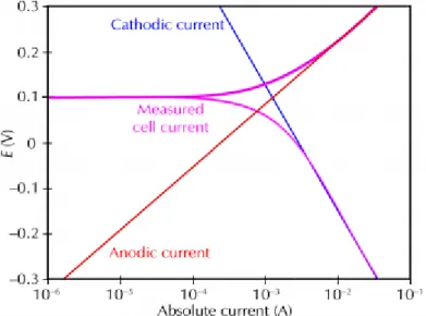
Fig. 2.4 Chloride threshold level recommendation by CEB-FIP II-11 Fig. 2.5 Definitions for chloride thresholds (based on Tuutti's model II-12 Fig. 2.6 Pourbaix diagram for Fe-H2O at 25°C II-15 Fig. 2.7 Schematic showing basics of the half-cell potential II-17 Fig. 2.8 A simply anodic-cathodic polarization curve II-18 Fig. 2.9 Schematic of measuring anodic-cathodic polarization curve II-19 Fig. 2.10 Cracking accelerates onset of corrosion, but over time corrosion
is similar in cracked and uncracked concrete
II-20
Fig. 2.11 Comparison allowable crack widths: severe exposure II-22 Fig. 2.12 Progress of deterioration progress due to chloride attack II-27 Fig. 2.13 Structural consequences of corrosion in reinforced concrete
structure
II-28
Fig. 2.14 Surface area of bars and strands II-30
Fig. 3.1 Layout of reinforcement bars in each beam III-4
Fig. 3.2 General view of exposure site III-5
Fig. 3.3 Bending test configuration III-6
Fig. 3.4 Examples of cut short pieces from the RC-S-B back tensile bar III-8 Fig. 3.5 Location of the tensile steel bars extracted from RC-S-A and
RC-S-B
III-8
Fig. 3.6 Crack appearance of 10-year-old beams III-10 Fig. 3.7 Appearance of RC-S-A after 20 years exposure III-11
Fig. 3.8 Crack opening on RC-S-A beam III-12
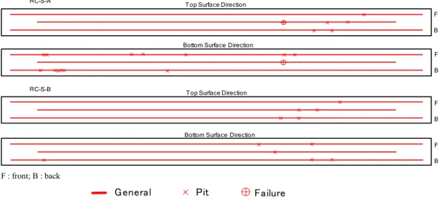
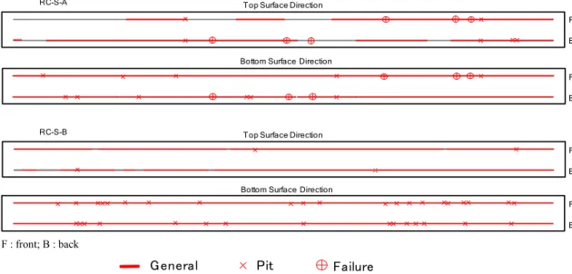
Fig. 3.9 Cracking maps of RC-S-A and RC-S-B beams after 40 years III-12
xvii Figure
No
Page
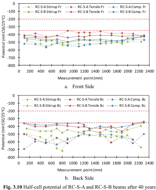
Fig. 3.10 Half-cell potential of RC-S-A and RC-S-B beams after 40 years III-13 Fig. 3.11 Crack formation in beams at ultimate load III-14 Fig. 3.12 Failure condition at the ultimate load III-15
Fig. 3.13 Chloride ion distributions III-16
Fig. 3.14 Corrosion maps for the tensile bars in upward and downward directions
III-17
Fig. 3.15 Corrosion maps for the compressive bars in upward and downward directions
III-18
Fig. 3.16 Corrosion maps for the stirrups III-19
Fig. 3.17 Stirrups III-20
Fig. 3.18 Cross-sectional loss of compressive and tensile bars based on weight measurements
III-20
Fig. 3.19 Condition of tensile bars before cleaning III-21 Fig. 3.20 Relationship between crack width and cross-sectional loss in
RC-S-B tensile bars
III-22
Fig. 3.21 Schematic of tensile test of steel bar III-23 Fig. 3.22 Failure points at ultimate load during tensile testing III-24 Fig. 3.23 Stress-strain curves for tensile tests of tensile bars and control III-25
Fig. 3.24 Load-displacement behavior III-27
Fig. 3.25 Progress of deterioration progress and performance degradation III-31 Fig. 3.26 Compressive strength and modulus of elasticity III-32
Fig. 4.1 Cross-sectional details of PC beams IV-4
Fig. 4.2 General view of exposure site IV-4
Fig. 4.3 PC beam specimens IV-6
Fig. 4.4 Bending test configuration IV-7
Fig. 4.5 Appearance of beams over 40 years of exposure IV-10
Fig. 4.6 Compressive strength of concrete IV-11
Fig. 4.7 Modulus of elasticity IV-12
Fig. 4.8 Porosity IV-13
xviii Figure
No
Page
Fig. 4.9 Chloride ion profile IV-13
Fig. 4.10 Determination of decompression load from the load- displacement data
IV-15
Fig. 4.11 Prestress force loss IV-16
Fig. 4.12 Change in flexural moment IV-17
Fig. 4.13 The corrosion state of reinforced bars of PC-O-3 and PC-R-1 beam
IV-18
Fig. 5.1 Detail of specimen (in mm) V-3
Fig. 5.2 (a) Pre-cracking loading; (b) Crack width measurement V-5
Fig. 5.3 Immersion and measurement condition V-5
Fig. 5.4 Half-cell potential of steel in OPC cement exposed to tap-water dry-wet cycle
V-7
Fig. 5.5 Corrosion current density of steel in OPC cement exposed to tap-water dry-wet cycle
V-7
Fig. 5.6 Half-cell potential of steel in OPC cement exposed to tap-water dry-wet cycle
V-8
Fig. 5.7 Corrosion current density of steel in OPC cement exposed to tap-water dry-wet cycle
V-9
Fig. 5.8 Half-cell potential of steel in OPC cement exposed to the three environments
V-10
Fig. 5.9 Corrosion current density of steel in OPC cement exposed to the three environments
V-10
Fig. 5.10 Half-cell potential of steel in BFS cement exposed to the three environments
V-11
Fig. 5.11 Corrosion current density of steel in BFS cement exposed to the three environments
V-12
Fig. 5.12 Anodic polarization curve 18 months (Effect of crack width) V-12 Fig. 5.13 Anodic polarization curve 18 months (Effect of concrete cover) V-13 Fig. 5.14 Anodic polarization curve 18 months (Effect of exposure V-13
xix Figure
No
Page
condition)
Fig. 5.15 Anodic polarization curve 18 months (Effect of SCMs) V-14 Fig. 5.16 Development of current for all specimen V-15
Fig. 5.17 Summary of corroded area V-17
Fig. 5.18 Steel bar corrosion at crack location V-17
Fig. 6.1 Shape and size specimen VI-4
Fig. 6.2 Type of reinforcing bar VI-7
Fig. 6.3 HCP tap-water mixing (OPC): tap-water and sea-water curing (Type I and III)
VI-9
Fig. 6.4 HCP sea-water mixing (OPC): tap-water and sea-water curing (Type II and IV)
VI-9
Fig. 6.5 HCP sea-water mixing (BFS50%): tap-water and sea-water curing (Type II and IV)
VI-10
Fig. 6.6 HCP tap-water mixing (OPC): tap-water curing (Type I) VI-11 Fig. 6.7 HCP sea-water mixing (OPC and BFS%): tap-water curing
(Type II)
VI-12
Fig. 6.8 HCP tap-water mixing (OPC): sea-water curing (Type III) VI-13 Fig. 6.9 HCP sea-water mixing (OPC and BFS%): sea-water curing
(Type IV)
VI-13
Fig. 6.10 Polarization curve tap-water mixing and curing (Type I) VI-14 Fig. 6.11 Maximum current from anodic polarization curve tap-water
mixing and curing (Type I)
VI-15
Fig. 6.12 Maximum current from anodic polarization curve sea-water mixing and tap-water curing (Type II)
VI-16
Fig. 6.13 Maximum current from anodic polarization curve tap-water mixing and sea-water curing (Type III)
VI-17
Fig. 6.14 Maximum current from anodic polarization curve sea-water mixing and curing (Type IV)
VI-18
Fig. 6.15 Polarization curve tap-water mixing and curing – in month VI-19
xx Figure
No
Page
(Type I)
Fig. 6.16 Maximum current from anodic polarization curve tap-water mixing and curing (Type I)
VI-19
Fig. 6.17 Maximum current from anodic polarization curve sea-water mixing and tap-water curing (Type II)
VI-20
Fig. 6.18 Maximum current from anodic polarization curve tap-water mixing and sea-water curing (Type III)
VI-21
Fig. 6.19 Maximum current from anodic polarization curve sea-water mixing and curing (Type IV)
VI-22
Fig. 6.20 Chloride ion distribution sea-water mixing: tap-water curing (Type II)
VI-23
Fig. 6.21 Chloride ion distribution tap-water mixing: sea-water curing (Type III)
VI-23
Fig. 6.22 Chloride ion distribution sea-water mixing: sea-water curing (Type IV)
VI-24
Fig. 6.23 Actual corrosion of OPC and bFS50% w/b 0.6 (Type IV) VI-25 Fig. 6.24 Actual corrosion of OPC w/b 0.5 (Type IV) VI-27 Fig. 7.1 Chloride transport process in a marine structure described by
BS 6349-1
VII-2
Fig. 7.2 Chloride content on RC and PC beams at a depth of 20~30 mm (Chapter 3 and Chapter 4)
VII-3
Fig. 7.3 Chloride content for crack and un-crack area after 18 months (Chapter 5)
VII-4
Fig. 7.4 Corroded area cracked concrete (Chapter 5) VII-6 Fig. 7.5 Relationship between cross-sectional loss and ultimate capacity
loss
VII-8
Fig. 7.6 Relationship between cross-sectional loss and ultimate capacity loss
VII-7
Fig. 7.7 Proposal on Deterioration progress and performance VII-8
xxi Figure
No
Page
degradation of RC (Chapter 3)
Fig. 7.8 Determination of decompression load from the load- displacement data (Chapter 4)
VII-11
I-1 Chapter 1
GENERAL INTRODUCTION
1. 1 Research Background
The corrosion of reinforcement, which commonly happens in a chloride environment, it is considered to be one of the major problems for the deterioration of reinforced concrete structures. The corrosion process leads to several coupled effects: longitudinal cracking of concrete cover due to expansive corrosion products; steel cross-section reduction; and the degradation of steel–concrete bond.
The corrosion affected by two phenomena particularly in the marine environment, either cracking or chloride penetration. The presence of cracks in reinforced concrete structure can reduce the service life and the load-bearing capacity of reinforced concrete elements by permitting more rapid access of moisture, chloride ions and oxygen to the steel bar, thus, causes the passive film damage and lead to corrosion initiation. Another major contributing factor is chloride attack. The most common causes of corrosion initiation in reinforcement is the local depassivation of steel due to the presence of chlorides at the reinforcement level.
Both crack and chloride could exist even from beginning or even during service life. Therefore, good handling and right countermeasure is need to solve these problems. As a way out for the right countermeasure, extensively research should have conducted by field and laboratory case. Field case by long-term exposure in natural corrosion environments would be provide important information regarding actual corrosion. Further, laboratory case by short-term with control conditions will provide an idealized information.
I-2 1. 2 Research Objectives
The aim of this study is to provides an overview related durability of RC and PC member due to initial defects under environmental action. Further, long-term exposure by field case (i.e., natural corrosion environments) and laboratory case (i.e., artificial corrosion environments) regarding of corrosion behavior and deterioration progress of RC and PC member is the main objective from this study.
Further, objective of this study to contributes and provides necessary information of the long-term behavior of a commonly used construction material, permitting the estimation of the behaviors of existing structures. The results of this study may guide engineers in the development of longer-lasting reinforcements for concrete structures.
The research objective was extended. In the last few decades, demanding of tap-water for concrete production increased extremely. In the other hand, availability of tap-water in the future need to be concern. Therefore, one of the interesting issue and became extended the aim of study is the potential of utilization sea-water mixed in concrete production.
1. 3 Research Contribution and Standing Point
This study completes an extended evaluation of the corrosion-related deterioration of RC and PC beams exposed to naturally corrosive environments. In particular, we examine the deterioration and properties of RC and PC beams after 40 years of exposure to maritime tidal and splash-zone environments. The resulting data set provides a clear demonstration of the effects of corrosion on pre-cracked and un-cracked RC and PC beams over the course of nearly half a century. Such information is necessary for the design and construction of long-lasting buildings and facilities in harsh environments.
The expected result of this study is to propose an overview assessment regarding durability evaluation of concrete member embedded steel due to corrosion based on the long-term exposure by field case and laboratory case.
Therefore, handling and right countermeasure could be planned for the future design of long-lasting performance of RC and PC member.
I-3 1. 4 Dissertation Outline
The configuration of each chapter is shown in Fig. 1.1. the dissertation is composed eight chapters as follows:
Chapter 1 describes the back ground of this study, research objective, research contribution and standing point.
Chapter 2 discuss literature review of previous studies on deterioration of RC and PC member in marine environment. Role of chlorides and concrete cracking as initial defects regarding durability overview and the issues to be addressed in this study.
Chapter 3 evaluates deterioration progress and performance reduction were experimentally evaluated in 40-year-old corroded reinforced concrete (RC) beams.
The corrosion process was natural, without acceleration by current application, admixture inclusion, or exposure to an artificial chloride environment. The mechanical performance of the beams was evaluated through a four-point bending test. The corroded steel reinforcing bars were extracted for corrosion evaluation and tensile testing.
Chapter 4 evaluates seven prestressed concrete beams (PC beam) were used for evaluation, consist of four post-tension beams (PC-O) and three pre-tension beams (PC-R). In order to investigate the effect of crack on prestress loss and bending capacity after long-term exposed, prestressed concrete beams were pre- crack and then exposed to marine environment. Experimental work was carried out to evaluate PC beams performance after long-term exposed.
Chapter 5 discuss on electrochemical evaluation of steel in cracked concrete.
Several reinforced concrete prisms with various of crack width and concrete cover were monitor and evaluate. The influencing parameters such as crack width, concrete cover, exposure condition and utilization of SCMs.
Chapter 6 discuss on potential of sea-water using in concrete production. The effect of sea-water as mixing water, and supplementary cementitious materials (SCMs), the experimental laboratory with electrochemical method was carried out.
Further, corrosion inhibitor such as epoxy-coated steel bar and stainless steel bar were evaluated.
I-4 Chapter 7 describes an overview for durability evaluation of RC and PC member. Provides necessary information for design of long-lasting performance concrete member.
Chapter convey summary, overview of findings and conclusions, and future research work.
Fig. 1.1 Structure of dissertation outline
CHAPTER 1 Introduction
CHAPTER 2
State of the Art on Corrosion of Reinforcing Steel Bar
CHAPTER 4 The Effect of Pre-cracked on Pre-Stressed Concrete Beams in Natural Corrosion
Environments
CHAPTER 5 Corrosion Rate of Steel in Cracked Concrete: Influence of Crack Width, Cover, Exposure Conditions and SCMs
CHAPTER 6 Long-term Evaluation of Electrochemical Behavior of Steel in Sea-water Mixed Mortar
CHAPTER 3 Deterioration Progress and Performance Reduction of 40- year-old RC Beams in Natural Corrosion Environments
CHAPTER 7
An Overview for Durability Assessment of RC and PC Member due to Corrosion
CHAPTER 8 Conclusions and Future Work
Cracking Chloride
Laboratory Case Field Case
I-5 References
[1.1] Amry Dasar, Hidenori Hamada, Yasutaka Sagawa and Daisuke Yamamoto.
Deterioration Progress and Performance Reduction of 40-Year-Old Reinforced Concrete Beams in Natural Corrosion Environments. Journal of Construction and Building Materials. 149(2017) pp.690-704.
[1.2] Amry Dasar, Hidenori Hamada, Yasutaka Sagawa and Daisuke Yamamoto.
Electrochemical Behavior of Steel in Cracked Concrete – Influence of Crack Width, Cover, Exposure Conditions and Supplementary Cementitious Materials (SCMs). Proceedings of Japan Concrete Institute, Vol. 39, 2017.
[1.3] Amry Dasar, Hidenori Hamada, Yasutaka Sagawa and Daisuke Yamamoto.
Recovery in Mix Potential and Polarization Resistance of Steel Bar in Cement Hardened Matrix During Early Age of Six Months [Sea-Water Mixed Mortar and Cracked Concrete]. Proceedings of Japan Concrete Institute, Vol. 38, No.1, 2016; pp.1203-1208.
[1.4] Amry Dasar, Rita Irmawaty, Hidenori Hamada, Yasutaka Sagawa and Daisuke Yamamoto. Prestress Loss and Bending Capacity of Pre-cracked 40 Year-Old PC Beams Exposed to Marine Environment. MATEC Web of Conferences, 47, 02008, 2016.
[1.5] Amry Dasar, Hidenori HAMADA, Yasutaka SAGAWA, Takanori IKEDA.
Durability of Marine Concrete with Mineral Admixture and Marine Aquatic Organism Layer. Proceedings of the International Conference on Sustainable Construction Materials & Technologies SCMT3 2013.
[1.6] Amry Dasar, Hidenori HAMADA, Yasutaka SAGAWA and Rita Irmawaty.
Corrosion Evaluation of Reinforcing Bar in Sea Water Mixed Mortar By Electrochemical Method. Proceedings of Japan Concrete Institute, Vol. 35, No. 1, 2013; pp.889-894.
[1.7] Amry Dasar, Hidenori HAMADA, Yasutaka SAGAWA, Takanori IKEDA.
Effectiveness of Marine Aquatic Organism as Concrete Surface Cover on Chloride Ingress into Concrete. Proceedings of JSCE 14th International Summer Symposium 2012. ISSN 1345-8507; pp.151-152.
[1.8] Masanouri ANNOURA, Amry Dasar, Hidenori HAMADA and Yasutaka SAGAWA. Electrochemical Properties of Reinforcing Bar in Mortar Sea
I-6 Water Mixing. Japan Society of Civil Engineers - West Branch Annual Meeting 2012, V-031. (In Japanese)
[1.9] Adiwijaya, Daisuke Yamamoto, Amry Dasar, Hidenori Hamada and Yasutaka Sagawa. Effects of Seawater Mixing and Curing on Strength and Carbonation of Fly Ash Concrete., 土木構造・材料論文集、第29号, No.29, 2013.12.
II-1
Chapter 2
STATE OF THE ART ON CORROSION OF REINFORCING STEEL BAR
2.1 Introduction
The corrosion of reinforcement, which commonly happens in a chloride environment, is considered to be one of the major problems for the deterioration of reinforced concrete structures, which has been the object of great attention from both researchers and engineers [2.1,2]. The corrosion process leads to several coupled effects: longitudinal cracking of concrete cover due to expansive corrosion products; steel cross-section reduction; and the degradation of steel–
concrete bond. As a result of these effects, the service life and the load-bearing capacity of reinforced concrete elements are considerably reduced. The corrosion of steel bars affects the performance of RC beams, causing increases in both the deflections and the crack widths under service loads, and decreases in the strength under ultimate loading [2.3].
Durability of reinforced concrete structures in marine environment depend on two problems [2.4]: (1) deterioration of concrete; (2) corrosion of reinforcing steel.
Further, the corrosion affected by two phenomena particularly in marine environment, either cracked on concrete surface or chloride penetration. Both crack and chloride could exist even from beginning or even during service life.
These two phenomena became important parameters and challenges in order to evaluate the durability of concrete member embedded steel. Therefore, extensively research should be conducted in order to evaluate the durability of concrete members with initial defects under environmental action.
II-2 2.2 Corrosion of Steel in Concrete
The fundamentals of corrosion are similar for prestressed and nonprestressed reinforcement. Steel in concrete is normally protected from corrosion by a passive film of iron oxides on the steel resulting from the alkaline environment of the concrete. Passivation of the steel may be destroyed by carbonation (CO2) or by the presence of chloride ions. In the absence of a passive film, corrosion may occur. The electrochemical process of corrosion requires several key elements, all of which must be present for corrosion to occur. The rate of corrosion is affected by many complex factors.
Corrosion is an electrochemical process in which steel is affected by a particular environment, resulting in a measurable loss of metal. The corrosion of steel bar means that iron is being removed from the steel. The liberated ferrous ions are then free to complex with hydroxyl ions to form various corrosion products depending on the availability of oxygen. The corrosion products can occupy up to six times as much volume as steel [2.5].
2.2.1. Corrosion Mechanism
After the passive layer is broken down, rust will appear instantly on the steel bar’s surface. The chemical reactions are the same in cases of carbonation or of chloride attack. When the corrosion of the reinforced steel bars in concrete occurs, they melt in the void that contains water [2.6]. Corrosion of steel in concrete is an electrochemical process with cathodic and anodic reactions. In the absence of chloride ions and a good quality concrete, the anodic reaction leads to the formation of iron cations as shown in Eq. (2.1):
Fe Fe2++ 2e− (2.1)
This reaction is balanced by the cathodic reduction of oxygen, which produces hydroxyl anions according to Eq. (2.1).
1
2O2 + H2O + 2e− 2OH− (2.2)
II-3 The reaction products between anodic and cathodic combine together to build the stability of the passive film on the steel. The stability of this passive film depends on the oxygen availability and the pH value in the interface of steel/concrete [2.7]. Corrosion start to initiate when the passive film is destroyed due to the presence of chloride ions at the steel-concrete interface.
In the presence of chloride ions, oxygen and water in concrete, they may act as a catalyst by introducing additional anodic reactions are represented in Eq.
(2.3).
Fe + 3Cl− FeCl3−+ 2e− followed by FeCl3−+ 2OH− Fe(OH)2+ 3Cl−
or
Fe + 4Cl− FeCl42−+ 2e−
followed by FeCl4−+ 2OH− Fe(OH)2+ 4Cl− or
Fe + 6Cl− FeCl33−+ 3e−
followed by FeCl33−+ 2OH− Fe(OH)2+ 6Cl− (2.3)
These reactions remove ferrous of ferric ions from the steel by forming complex ions with the chlorides then deposited near the anode where they join with hydroxyl ions to form various corrosion products. The chloride ions are released to repeat the process. Secondary reactions may occur due to the expansive products of corrosion. Although the Fe2+ and OH− ions both diffuse into the concrete (from anode to cathode, respectively), the corrosion products form near the anode because the OH− ions are smaller and more diffuse through the concrete more readily [2.8]. If the supply of oxygen is restricted, ferrous oxides and hydroxides form (Eq. (2.4) and Fig 2.1):
Fe2++ 2(OH)− Fe(OH)2 or
![Fig. 2.9 Schematic of measuring anodic-cathodic polarization curve Table 2.4 Grade of passivity film associated anodic polarization curve [2.64]](https://thumb-ap.123doks.com/thumbv2/123deta/9919045.1919943/50.892.223.711.615.817/schematic-measuring-anodic-cathodic-polarization-passivity-associated-polarization.webp)
![Fig. 2.10 Cracking accelerates onset of corrosion, but over time corrosion is similar in cracked and uncracked concrete [2.70]](https://thumb-ap.123doks.com/thumbv2/123deta/9919045.1919943/51.892.277.653.589.893/cracking-accelerates-corrosion-corrosion-similar-cracked-uncracked-concrete.webp)