1
Study on Modification of Chemical
Composition in Layered Niobate
Perovskites and its Photocatalytic
Degradation of Organic Species
(層状ニオブ酸ペロブスカイトの化学組
成制御とその有機物分解に関する研究)
山梨大学大学院
医学工学総合教育部
博士課程学位論文
学籍番号 G12DGA01
氏名 XU Nan
(徐 楠)
指導教員 武井 貴弘
卒業年月 平成 27 年 9 月
2
目录
CHAPTER I Preface... 4 1.1. General introduction... 4 1.1.1 Definition of photocatalysis ... 5 1.1.2 Mechanism ... 7 1.2. Applications of photocatalysts ... 10 1.2.1. Anti-bacterial effect ... 10 1.2.2. Water splitting ... 111.2.3. Air and water purifying effect ... 12
1.2.4. Anti fogging, self-cleaning ... 13
1.2.5. Deodorizing Effect ... 14
1.3. The strategies for enhancing the efficiency of photocatalitic activity ... 15
1.3.1. Doping and substitution ... 15
1.3.2. Surface modification by noble metal ... 15
1.3.3. Cocatalyst loading ... 17
1.4. Purpose of the study ... 18
References ... 20
CHAPTER II Photocatalytic Activities of Layered Niobate Perovskite (A'An-1NbnO3n+1, A: Ca, La) with Substitution of Ti and W for Nb... 23
2.1. Introduction ... 23
2.2. Experimental section ... 25
2.2.1. Synthesis and characterization ... 25
2.2.2. Photocatalysis Measurements ... 26
2.3. Results and discussion ... 26
2.3.1. Preparation of partially-Substituted Layered Perovskites... 26
2.3.2. Optical Band Gap and Photocatalytic Activities ... 29
2.4. Summary ... 37
3
CHAPTER III Study on Effect of Pt hybridization by photoirradiation with
Layered Niobate Perovskite for Photocatalytic Behavior ... 41
3.1. Introduction ... 41
3.2. Experimental section ... 43
3.2.1. Materials preparation ... 43
3.2.2. Characterization ... 44
3.3. Results and discussion ... 45
3.4. Summary ... 62
References ... 63
CHAPTER IV Preparation and Phase Transformation of Ag Ion-exchanged Layered Niobate Perovskite and Their Photocatalytic Properties ... 66
4.1. Introduction ... 66
4.2. Experimental section ... 67
4.3. Results and discussion ... 71
4.3 Summary ... 84 References ... 85 CHAPTER V Summary ... 87 List of Publications... 90 List of Awards ... 90 List of Presentations ... 91 Acknowledgement ... 93
4
CHAPTER I PREFACE
1.1. General introduction
With the rapid development of industrialization and urbanization, the abusive use of industrial and agricultural chemicals, the unreasonable dispose of combustion byproducts and chemical waste have become more and more serious and frequently [1]. As a result, a great amount of contaminants have been undesirably released to water system including underground water, surface water, sewage water, drinking water, which have already exceeded the self-healing capacity of nature [2-5]. The main solutions of these polluting problems could be divided into two categories, physical treatment approaches (ultra-filtration, adsorption, coagulation, exchange etc.) and chemical degradation methods (supercritical water oxidation, the Fenton method, ozone/UV radiation/H2O2 oxidation, sonochemical destruction, electrochemical
treatment, semiconductor photocatalysis, enzymatic treatment, etc.) [6, 7]. Among these methods, semiconductor photocatalysis has attracted fascinated significant attention for environmental cleanup during recent years, since it is a green chemical method for degrading majority of contaminants in water and air with the activation of natural solar light in the ambient conditions [8-10]. Therefore, the development of high efficiency solar light induced photocatalysts becomes a hot topic for researchers reasonably. Two prevalent strategies were proposed to meet this demand. The first
5
method is to modify the most promising photocatalysts (TiO2, perovskites, etc.) by
doping, substituted, loading or coupling with other substances [11, 12]. The other way is to develop other new efficiency compounds for photocatalysis utilization.
In this chapter, a general introduction of photocatalysis including the definition and classification, the mechanism and the relevant environmental cleanup applications were introduced in details. In addition, the structure and properties of common photocatalysts was also depicted. Furthermore, the brief review of the strategies to improve the visible and NIR lights responsive photocatalysts was given. Finally, the research purpose of this thesis was concluded.
1.1.1 Definition of photocatalysis
Photocatalysis is defined as acceleration of chemical reaction by the presence of an irradiated catalyst which does not change itself or being consumed in the chemical reaction [13, 14]. This definition of photo-catalysis has close relation with photosensitization, a process by which a photochemical alteration occurs in one molecular entity as a result of initial absorption of radiation by another molecular entity.
For example, chlorophyll in plants could be considered as a type of photocatalyst. Photocatalysis compared to photosynthesis, in which chlorophyll captures sunlight to turn water and carbon dioxide into oxygen and glucose, photocatalysis creates strong oxidation agent to breakdown any organic matter to carbon dioxide and water in the presence of photocatalyst, light and water.
6
TiO2 is the most common photocatalyst [15]. It has many advantages, such as
low-cost, high photocatalytic effect, none-Toxic, and so on. Approved by the food testing laboratory of the United States Food and Drug Administration (FDA), Titanium Dioxide is considered as a safe substance and harmless to human. It is commonly used in paint, printing ink, plastics, paper, synthetic fibers, rubber, condensers, painting colors and crayons, ceramics, electronic components along with food and cosmetics. Many studies have been published on the use of titanium dioxide as a photocatalyst for the decomposition of organic compounds [16-18]. After illuminated by light, titanium dioxide produces hydroxyl radicals, which react with the organic matters in the air to form non-toxic inorganic matters [19, 20].
7
1.1.2 Mechanism
Because of the explosive increase of world’s population and fast growth of developing industry, the environmental pollution and green-house problems become more and more serious. Semiconductors play important role in our daily life including solar cells, light-emitting diodes, transistors, sensor, quantum dots and digital and analog integrated circuits, etc. Semiconductor is a unique substance, whose electrical conductivity is between conductor (such as metals) and insulator (such as glass). The conductivity of semiconductor usually increases with increasing temperature, which is opposite to that of metal, and insulator presents no conductivity. The peculiar electronic structure of semiconductor is represented by its valence band (VB) and conduction band (CB) [19, 21]. The band gap of semiconductor is defined as the distance of the utmost of conduction band and the lowest of the valence band [22]. As far as the semiconductor photocatalyst is concerned, the relative band positions of VB and CB are of great importance since they can determine the light-harvesting capability and the redox performance of a photocatalyst [15, 23, 24].
8
Figure 1-2 Possible mechanism for the semiconductor photocatalysis.
The precise definition of photocatalysis can be obviously observed in Fig. 1-2. In photochemistry, the role of photocatalyst is used to initiate or boost some reduction and oxidation reactions with the existence of irradiated semiconductor. When the semiconductor photocatalyst is irradiated by a light whose energy is equal to or greater than the band gap (Eg) of semiconductor, the electron (e-) in the VB can be
excited to the CB by leaving a positive hole (h+) in the VB (Eq. 1-1)[25]. As a result, three possible processes will happen. The first is that the photogenerated electron-hole pairs will be captured by the defects in bulk or on the surface of semiconductor [26]. The second process is the recombination of photoinduced electron-hole pairs and releases heat or the light again. The last result is the migration of photoexcited electron-hole pairs to the surface of semiconductor [27]. The first two processes are
9
commonly recognized as deactivation ways since the photogenerated electron-hole pairs can’t be utilized for the photocatalytic redox reaction. However, the third migration process could be utilized for the photocatalytic performance. In this process, the photogenerated hole in the valence band (hVB+)can react with OH- or water on the
surface of semiconductor to produce ·OH radicals (Eq. 1-2 and1-3), which can be used as one of the most active oxidants. The as-induced ·OH radicals are able to further oxidize the organic contaminants with mineralization producing CO2 and H2O
(Eq. 1-4).Meanwhile, the photoproduced electron in the conduction band (eCB-) will
be trapped by the absorbed O2 on the surface of semiconductor to form superoxide
radical anion (O2·-) (Eq. 1-5). Besides, the O2·- enables to further react with H+ to
produce hydroperoxyl radical (·OOH) (Eq. 1-6), finally leading to the production of H2O2 (Eq. 1-7). The above mentioned oxygen related species may also dedicate to the
oxidation of pollutants as well as the reduction of contaminants. (Eq. 1-8 and 1-9). Therefore, the semiconductor photocatalysts can be environmental friendly used to degrade organic pollutants and toxic gases in the water and air under the irradiation of suitable light sources [28, 29].
Photocatalyst + hν→ hVB+ + eCB- (1-1)
hVB+ + OH- → ·OH (1-2)
hVB+ + H2O → ·OH + H+ (1-3)
10
eCB- + O2 → ·O2- (1-5)
·O2- + H+ → ·OOH (1-6)
·OOH + ·OOH → H2O2 + O2 (1-7)
·O2- + pollutant → Oxidation/reduction products (1-8)
·OOH/ H2O2 + pollutant → Oxidation/reduction products (1-9)
1.2. Applications of photocatalysts
Because of the explosive increase of world’s population and fast growth of developing industry, the environmental pollution and green-house problems become more and more serious. Therefore, the semiconductor photocatalysis, as a green chemical method to solve these issues, has attracted increasing attention and has also been extensively used in many areas such as food, print, cosmetics, medicine, water and air purification, energy conversion and so on. As a result, the applications of photocatalyst for water decontamination, air purification, water splitting and self-cleaning have been briefly introduced as follows [30-32].
1.2.1. Anti-bacterial effect
Photocatalysis reactions could restrain bacteria completely because photocatalyst cannot only kill bacteria cells, but also decompose the cell [31]. Comparing with a lot of chemical and biology antibacterial agent, the titanium dioxide photocatalyst has been proved to be more effective. The photocatalytic can even works while the
11
bacteria are actively propagating. Besides, the endotoxin produced during the death of cell is also expected to be decomposed by photocatalytic action. Another advantage of photocatalysis is that photocatalyst such as titanium dioxide does not deteriorate or consume. Unlike chemical and biological antibacterial, photocatalyst shows a long-term anti-bacterial effect. Generally speaking, disinfection by titanium oxide is three times stronger than chlorine.
1.2.2. Water splitting
Because of the explosive increase of world’s population and fast growth of many developing industry and daily consumption of resource, the energy is becoming more and more shortage. Meanwhile, the released CO2 in atmosphere, as a result of the
combustion of the carbon-based fuels, has also significantly enhanced and intensify the green house effect. In this case, the energy depletion and environmental contamination have been two essential issues in modern times and a renewable and infinite energy source is strongly required. Since Fujishima and Honda firstly generated hydrogen by water photoelectrolysis, the hydrogen fuel by solar-chemical energy conversion has been gradually considered as a promising alternative for environmental benign and renewable energy source, which can be produced from the abundant of water without the release of CO2 and other contaminating gas. After that,
many efforts and attentions have been inputted to improve the high efficiency of hydrogen production by the photocatalysis. Fig. 1-3 illustrates a simple
12
photoelectronchemical water splitting system to produce hydrogen in the presence of TiO2 photocatalyst under the light irradiation [33].
Figure 1-3 Schematic of water splitting by TiO2 photocatalys.
1.2.3. Air and water purifying effect
The photocatalytic reactivity can be applied on air and water purification process. The polluted compounds in air and water system, such as NOx, cigarette smoke, bacteria, viruses and volatile compounds arising from various construction materials can be effectively eliminated by purification system with photocatalysts. Atmospheric constituents such as chlorofluorocarbons (CFCs), CFC substitutes, greenhouse gases, and nitrogenous and sulfurous compounds undergo photochemical reactions either
13
directly or indirectly in the presence of sunlight. In a polluted area, these pollutants can eventually be removed [34].
Photocatalyst coupled with UV lights can oxidize organic pollutants into nontoxic materials, such as CO2, CH3CHO, and water and can disinfect certain bacteria. This
technology is very effective at removing further hazardous organic compounds (TOCs) and at killing a variety of bacteria and some viruses in the secondary wastewater treatment. Pilot projects demonstrated that photocatalytic detoxification systems could effectively kill fecal coliform bacteria in secondary wastewater treatment.
1.2.4. Anti fogging, self-cleaning
A considerable amount of buildings in Asian and European countries have been contaminated after used for no more than 5 years. The external walls of these building become soiled by automotive exhaust fumes with a high density of oily components. Some manufacturer have tried to paint the original building materials with coating include photocatalyst, which could form a hydrophilic protective film of titanium to provide self-cleaning and antistatic properties [35, 36]. The hydrocarbon from automotive exhaust will be oxidized and the dirt on the walls could be washed away with rainfall, keeping the building exterior clean at all times.
14
1.2.5. Deodorizing Effect
The photocatalysts could also be used on the deodorizing applications. The hydroxyl radicals produced by photocatalysts after absorbing solar light will accelerate the breakdown of any Volatile Organic Compounds (VOCs) by breaking the molecular bonds. During photocatalysis process, the harmful organic gases, such as formaldehyde, can decompose and form a single molecule to enhance the air cleaning efficiency. It is reported that the odor molecules that can be decomposed include tobacco odor, nitrogen dioxide, urine and fecal odor, gasoline, and many other hydro carbon molecules in the atmosphere.
A lot of manufactures have invented air purifier with TiO2 and other
photocatalysts. They declare that these newly invented air purifier can prevent and eliminate smoke, fog, dust, pollen, bacteria, virus and harmful gas in the air with filtering percentage of 99.9% because of adding highly oxidizing effect of photocatalyst(TiO2).
15
1.3. The strategies for enhancing the efficiency of photocatalitic activity
The development of high efficiency solar light induced photocatalysts becomes a hot topic for researchers and a lot of promising photocatalysts have been developed up to now. However, there is still a big gap of the photocatalytic efficiency and light-harvesting ability from industrial requirement for the practical application. Therefore, a lot of strategies, such as doping, noble metal plasmon, co-catalyst loading, sensitizing and semiconductor coupling, etc. have been adopted to improve these performances. A brief review for these improvement strategies prevelent in recent years are shown as follows.
1.3.1. Doping and substitution
In order to increase photocatalytic efficiency and light-harvesting ability by increasing the light responsive ability in whole light range and enhancing the charge carriers’ separation ability, doping different ions to the target photocatalysts has been considered as one of the most potential methods because doping in crystal can induce some intermediate energy levels in the forbidden band and also sometimes increase the electron-hole pairs' separation. There are a lot of doping methods including nonmetal doping, metal doping, nonmetal and metal codoping.
1.3.2. Surface modification by noble metal
Recently, the surface plasmon resonance (SPR) effect has drawn a great deal of attention in the improvement of visible light absorption ability of photocatalysts by
16
loading noble metal nanoparticles (e.g., Ag, Au, Pt). SPR is defined that when a spherical noble metal nanoparticle is irradiated by light with the wavelength much longer than the size of this particle, the charge density in the noble metal powder will be redistributed. Meanwhile, a coulombic restoring force is going to be established, and the charge density will coherently oscillate just like a harmonic oscillator in particle with the incident light. In a word, surface plasmon resonance is collective oscillations of electrons in the conduction band of noble metal induced by the electromagnetic field of the incident light. As noble metal is loaded on the surface of photocatalyst and illuminated by a visible light, noble metal can be excited by visible light owing to the effect of surface plasmon resonance and then photogenerated electron can be further transferred to the photocatalyst to produce photocatalysis. For example, Z. K. Zheng, et al.[38] prepared the noble metals (Au, Pt and Ag) loaded TiO2 nanoparticles by a facile in situ method using the Ti3+ as the reduction reagent.
The visible light induced oxidation of benzene to phenol has been investigated for the photocatalytic activities of samples. The results found that due to the SPR effect of noble metal loading, the noble metal was excited by the visible light, and then the photoinduced electron was transferred from noble metal to the TiO2 particles, finally
presenting a high yield (63%) and selectivity (91%) for the oxidation of benzene to phenol. The corresponding mechanism for high efficiency of visible light induced photocatalytic activity of samples is shown in Fig. 1-5.
17
Figure 1-5 Proposed mechanism for the surface plasmon resonance induced
photocatalytic activity of samples under the irradiation of visible light.
1.3.3. Cocatalyst loading
The method of cocatalyst loading has become one of the most potential approaches, which could significantly improve the separation ability of charge carriers. From Fig. 1-6, we can find that the photocatalytic mechanism for water splitting by a semiconductor photocatalyst loaded with a series of cocatalysts[39]. We could clearly find that the photogenerated electron or hole can be transferred from photocatalyst to the cocatalyst during photocatalysis process under the irradiation of light with the loading of cocatalyst on the surface of photocatalyst. In this case, the photoinduced electron-hole pairs are able to be effectively separated. Furthermore, the loading cocatalyst on the surface of semiconductor photocatalyst has improved the
18
photocatalytic stability of products. As a result, the cocatalysts can be divided into two main types, containing electron capturing and hole capturing. NiO, CuO, Cu2O,
Cr2O3, RuO2, MoS2, graphene, etc. are usually regarded as the electron capturing
cocatalysts.
Figure 1-6 Proposed photocatalytic mechanism for water splitting by a
photocatalyst with the loading of various cocatalysts.
1.4. Purpose of the study
During recent years, photocatalysis as a green chemical approach for environmental cleanup has attracted a great deal of attentions from world-wide researchers. Therefore, a series of new photocatalysts, such as A’(An-1BnX3n+1)
19
worsening atmosphere. At this moment, great efforts are still needed to further improve the effect of solar light induced photocatalysis for the practical application. Therefore, the effective methods to produce new layered perovskites with higher photocatalytic performance are urgently required.
As introduced above, in this thesis, some promising methods have been proposed to enhance the phtocatalytic activity of layered perovskites. In order to improve photocatalytic activity, firstly, we want to use Ti and W particle substituted Nb in RbLaNb2O7 layered perovskite, being eager for enhance the degradation of phenol by
narrowing band gap. Secondly, in order to further improve the separation ability of photogenerared electron-hole pairs, we want to use noble metal Pt to hybridization with HLaNb2O7. Thirdly, because of Ag or Bi ions have been found to increase
valence band energies due to interactions between the O 2p orbital and the Ag 4d or Bi 6s orbital, so we want to fabricate a new series of layered perovskite photocatalysts with Ag or Bi intercalated in HLaNb2O7 via an ion-exchanged method. With these
three strategies, we are looking forward to get novel layered perovskite with higher photocatalytic activity.
20
References
1. N. A. Ramos-Delgado, M. A. Gracia-Pinilla, L. Maya-Trevino, L. Hinojosa-Reyes, J. L. Guzman-Mar and A. Hernandez-Ramirez, Journal of
hazardous materials, 2013, 263 Pt 1, 36-44.
2. D. K. Dogutan, R. McGuire, Jr. and D. G. Nocera, Journal of the American
Chemical Society, 2011, 133, 9178-9180.
3. T. A. Saleh, M. A. Gondal, Q. A. Drmosh, Z. H. Yamani and A. Al-yamani,
Chemical Engineering Journal, 2011, 166, 407-412.
4. H. Irie, T. Shibanuma, K. Kamiya, S. Miura, T. Yokoyama and K. Hashimoto,
Applied Catalysis B: Environmental, 2010, 96, 142-147.
5. D. Suryaman, K. Hasegawa and S. Kagaya, Chemosphere, 2006, 65, 2502-2506.
6. W. Zhao, Z. Ai, X. Zhu, M. Zhang, Q. Shi and J. Dai, International Journal of
Hydrogen Energy, 2014, 39, 7705-7712.
7. Y.-R. Jiang, W. W. Lee, K.-T. Chen, M.-C. Wang, K.-H. Chang and C.-C. Chen, Journal of the Taiwan Institute of Chemical Engineers, 2014, 45, 207-218.
8. P. Chowdhury, H. Gomaa and A. K. Ray, Chemosphere, 2015, 121, 54-61. 9. J. Prince, F. Tzompantzi, G. Mendoza-Damián, F. Hernández-Beltrán and J. S.
Valente, Applied Catalysis B: Environmental, 2015, 163, 352-360.
10. X. Xiao, J. Jiang and L. Zhang, Applied Catalysis B: Environmental, 2013,
142-143, 487-493.
11. Y. Li, J. Wu, Y. Huang, M. Huang and J. Lin, International Journal of
21
12. C. Ren, L. Zhou, Y. Duan and Y. Chen, Journal of Rare Earths, 2012, 30, 1106-1111.
13. S. Royer, D. Duprez, F. Can, X. Courtois, C. Batiot-Dupeyrat, S. Laassiri and H. Alamdari, Chemical reviews, 2014.
14. Y. Ono and K.-i. Katsumata, Applied Clay Science, 2014, 90, 61-66.
15. P. Shen, J. C. Lofaro, W. R. Woerner, M. G. White, D. Su and A. Orlov,
Chemical Engineering Journal, 2013, 223, 200-208.
16. S. H. Lin, C. H. Chiou, C. K. Chang and R. S. Juang, Journal of
environmental management, 2011, 92, 3098-3104.
17. S. Yang, J.-S. Gu, H.-Y. Yu, J. Zhou, S.-F. Li, X.-M. Wu and L. Wang,
Separation and Purification Technology, 2011, 83, 157-165.
18. S. Liu, J. Huang, L. Cao, J. Li, H. Ouyang, X. Tao and C. Liu, Materials
Science in Semiconductor Processing, 2014, 25, 106-111.
19. X. Wu, S. Yin, Q. Dong, C. Guo, T. Kimura, J.-i. Matsushita and T. Sato, The
Journal of Physical Chemistry C, 2013, 117, 8345-8352.
20. S. Wang, L. Yi, J. E. Halpert, X. Lai, Y. Liu, H. Cao, R. Yu, D. Wang and Y. Li, Small, 2012, 8, 265-271.
21. K. M. Parida and S. Parija, Solar Energy, 2006, 80, 1048-1054.
22. C. H. Chiou and R. S. Juang, Journal of hazardous materials, 2007, 149, 1-7. 23. Y. Yang, H. Liang, N. Zhu, Y. Zhao, C. Guo and L. Liu, Chemosphere, 2013,
93, 701-707.
24. S. Zhang, S. Zhang and L. Song, Applied Catalysis B: Environmental, 2014,
22
25. C. L. Bianchi, S. Gatto, C. Pirola, A. Naldoni, A. Di Michele, G. Cerrato, V. Crocellà and V. Capucci, Applied Catalysis B: Environmental, 2014, 146, 123-130.
26. J. Liu, Y. Sun, Z. Li, S. Li and J. Zhao, International Journal of Hydrogen
Energy, 2011, 36, 5811-5816.
27. S. Chen, Y. Hu, L. Ji, X. Jiang and X. Fu, Applied Surface Science, 2014, 292, 357-366.
28. I. K. Konstantinou and T. A. Albanis, Appl. Catal. B 2004, 49, 1-14. 29. K. Pirkanniemi and M. Sillanpaa, Chemosphere 2002, 48, 1047-1060.
30. C. Chen, W. Ma and J. Zhao, Chemical Society reviews, 2010, 39, 4206-4219. 31. J. Xing, W. Q. Fang, H. J. Zhao and H. G. Yang, Chemistry, an Asian journal,
2012, 7, 642-657.
32. W. Xie, W. Hu, L. Zou and D. Bao, Ceramics International, 2015. 33. F. E. Osterloh and B. A. Parkinson, MRS Bull. 2011, 36, 17-22.
34. S. Suárez, R. Portela, M. D. Hernández-Alonso and B. Sánchez, Environ. Sci.
Pollut. Res. 2014, 21, 11208-11217.
35. F. Yang, Y. Takahashi, N. Sakai and T. Tatsuma, The Journal of Physical
Chemistry C, 2011, 115, 18270-18274.
36. T. Shibata, H. Irie and K. Hashimoto, Chemical communications, 2009, 3735-3737.
37. http://coating-glass.com.tw/english/buss.php?no=6
38. Z. K. Zheng, B. B. Huang, X.Y. Qin, X. Y. Zhang, Y. Dai and M. H. Whangbo.
J. Mater. Chem. 2011, 21, 9079-9087.
39. J. R. Ran, J. Zhang, J. G. Yu, M. Jaroniec and S. Z. Qiao. Chem. Soc. Rev. 2014,
23
CHAPTER II PHOTOCATALYTIC ACTIVITIES
OF LAYERED NIOBATE PEROVSKITE
(A'A
N-1NB
NO
3N+1, A: CA, LA) WITH
SUBSTITUTION OF TI AND W FOR NB
2.1. Introduction
In modern society, water pollution by organic and inorganic contaminants has attracted a widespread public concern [1-4]. A typical group of organic contaminants is the phenol and the derivative such as benzenetriol, chlorophenol and catechol [5-8]. These compounds are some of the most refractory contaminants and are transformed or degraded very slowly by natural processes [9]. Phenol and its derivatives are widespread used in agriculture, petrochemical and the production of textile, paint, plastic, pesticides and dyes [10, 11]. Due to their high stability, environmental toxicity, and bio-accumulation nature, these compounds are potential hazards to human health and the aquatic ecosystem [12-15].
An ideal water treatment process should be able to mineralize all the toxic species without leaving any hazardous residues and also be cost-effective [2, 16]. So far, none of the conventional treatment technology, such as biological degradation, chlorination, incineration, solvent extraction, air stripping, adsorption by granulated activated carbon and membrane separation process could approach this ideal criterion [17-20].
24
Heterogeneous photocatalysis has been proposed as an alternative for the treatment of organic pollutants in recent years since the report of the n-doped TiO2
photoelectrode under ultraviolet light [18, 21-23]. The advantages of photocatalysis include low operation temperature, low cost photocatalyst, and significantly low energy consumption, which have led the relevant application of photocatalysis to the stage of commercialization [24-26]. Discovery of new and high efficient photocatalytic metal-oxides to convert solar energy into chemical fuels has great importance [27, 28]. Among the many explored photocatalysts, layered metal-oxides have shown much promise in exhibiting some of the highest photocatalytic rates and quantum efficiencies for the degradation of organics, including La2Ti2O7, Sr2Ta2O7,
La4CaTi5O16, HCa2Nb3O10, and Rb4Nb6O17 [11, 19, 29-32].
The A'An-1BnO3n+1 is a general formula of Dion−Jacobson type layered niobate
perovskite [23, 33]. The Dion-Jacobson series of layered perovskites has one interlayer cation per formula unit [34, 35, 36]. Ruddlesden-Popper phases A’2(An-1BnO3n+1) have two interlayer cations per formula unit and possess twice the
interlayer charge density of the Dion-Jacobson phases [37]. Such perovskite structure has capable of undergoing substitution reaction with other elements which have similar ionic radius to cation in B site. The substitution sometimes gives change of the band structure. In the case of niobate (Nb in B site), titanium and tungsten are strong candidates for the substituent to the A'An-1NbnO3n+1 because of their similar ionic radii.
25
KCa2Nb3-2xTixWxO10 (x=0,0.15, and 0.3 respectively) have been synthesized and the
products were characterized by X-ray diffraction and ultra-violet–visible spectra. The influence of the partial substitution of Nb and W on the photo-catalytic activity of pure RbLaNb2O7 was evaluated using the degradation of phenol.
2.2. Experimental section
2.2.1. Synthesis and characterization
RbLaNb2O7 was prepared by high-temperature solid-state process. A mixture of
reagent-grade Rb2CO3, La2O3, Nb2O5 with a mole ratio of Rb : La : Nb = 1.25 : 1 : 2
was well ground with ethanol in an agate mortar. For Ti and W substituted material, the substituted amount, x of 0.1 and 0.2 were examined in the general formula, RbLaNb2-2xTixWxO7. After grinding, the mixture was heated in a combustion boat at
1000 oC for 6 hours, and then cooled to room temperature. The substituted KCa2Nb3O10 was also synthesized by similar solid-state reaction with the different
temperature at 1100 oC for 6 hours. The obtained white powders were characterized as the desired niobate RbLaNb2O7 and KCa2Nb3O10 by powder X-ray diffraction with
monochromated CuKa radiation (RINT2000, rigaku). The samples were examined for their optical band gap by UV-vis spectra (V-550, Jasco)
26
2.2.2. Photocatalysis Measurements
The photocatalytic activity was evaluated by the phenol degradation. For consideration of practical application, Xe light was used as irradiation resource. Phenol aqueous solution at a concentration of 20 ppm was prepared from ultrapure water, and the sample was put into the phenol solution at a concentration of 3 g/L. Solution was stirred in dark condition (no irradiation of visible light) for 1 hour to examine the adsorption balance of phenol. After 1 hour, the solution was irradiated by ultraviolet light from 300 W Xe lamp (UXR-300DU, Ushio Inc.). The solution of 2 milliliters was extracted at 30, 60, 90, 120, 150, 180, 210 and 240 min of elapsed time. The concentration of phenol in solution was measured by high performance liquid chromatography (co-2065, Jasco).
2.3. Results and discussion
2.3.1. Preparation of partially-Substituted Layered Perovskites
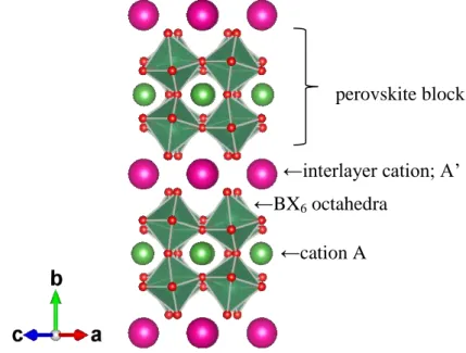
Fig. 2-1 (a) is the crystal structure of Dion-Jacobson A’(An-1BnX3n+1) type layered
perovskite. As RbLaNb2O7 for example, O is on the vertex site of octahedron and Nb
is in the center of the octahedron. La atom is surrounded by NbO6 octahedra to form
perovskite block. The perovskite block has negative charge in spite of Nb5+ and La3+ due to the Nb/La ratio of 2. Rb exists between the perovskite blocks for charge compensation. In the case of KCa2Nb3O10, Ca locates between the NbO6 octahedra.
27
Since valence of Ca2+ is smaller than La3+, three NbO6 octahedron sheet overlapped with linking at shared oxygen within one perovskite slab.
Figure 2-1 (a) Crystal structure of Dion-Jacobson A’(An-1BnX3n+1) type layered
perovskite.
Figure 2-1 (b) DOS curves of RbLaNb2O7 calculated by DV-X method
Fig. 2-1 (b) shows DOS curves of RbLaNb2O7 calculated by DV-X method26). These
curves confirm that conduction band composes of La 4f and Nb 4d. Such band structure may be affected by the substitution of Ca for La and Ti and W for Nb. Fig.
perovskite block
←BX6 octahedra
←interlayer cation; A’
28
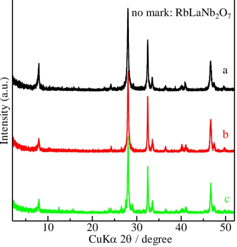
2-2 shows the XRD patterns of samples, RbLaNb2O7, RbLaNb1.8Ti0.1W0.1O7 and
RbLaNb1.6Ti0.2W0.2O7. All the diffraction peaks in these patterns were attributed to the
RbLaNb2O7-type perovskite structure and no impurity peaks appeared, indicating that
the substitution of Ti and W made no visible change on the formation of RbLaNb2O7
structure during the solid-stated reaction process.
Figure 2-2 XRD patterns of samples: (a) RbLaNb2O7, (b) RbLaNb1.8Ti0.1W0.1O7,
(c) RbLaNb1.6Ti0.2W0.2O7
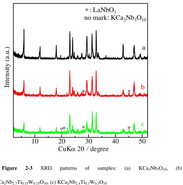
Fig. 2-3 shows the XRD patterns of KCaNb3O10, KCa2Nb2.7Ti0.15W0.15O10 and
KCa2Nb2.4Ti0.3W0.3O10. There are some impurity peaks in these patterns. In addition,
ratio of the diffraction intensities seems to change on the substitution. These changes
CuK
/ degree
In
te
n
si
ty
(
a
.u
.)
a
b
c
no mark: RbLaNb
2O
710
20
30
40
50
29
may results from the orientation of the crystallite. Thus, the substitution treatment into KCa2Nb3O10 posed generation of a small amount of impurities and/or change of the
particle shape of the matrix phase.
Figure 2-3 XRD patterns of samples: (a) KCa2Nb3O10, (b)
KCa2Nb2.7Ti0.15W0.15O10, (c) KCa2Nb2.4Ti0.3W0.3O10
2.3.2. Optical Band Gap and Photocatalytic Activities
Fig. 2-4 (a) shows the UV-vis spectra of RbLaNb2O7 and relatives, these UV-vis
spectra shows steep absorption edge at around 350-400nm in wavelength. From Tauc plots (Fig. 2-4 (b)) we can see the estimated band gap energies at X-intercept. The estimated band gap energies of RbLaNb2O7, RbLaNb1.8Ti0.1W0.1O7 and
CuK
/ degree
In
te
n
si
ty
(
a
.u
.)
a
b
c
: LaNbO
3no mark: KCa
2Nb
3O
10*
*
*
*
*
*
*
10
20
30
40
50
30
RbLaNb1.6Ti0.2 W0.2O7 are 3.37, 3.35 and 3.30, respectively. Fig. 2-5 (a) shows the
UV-vis spectra of KCa2Nb3O10 and relatives. In these spectra, absorption by
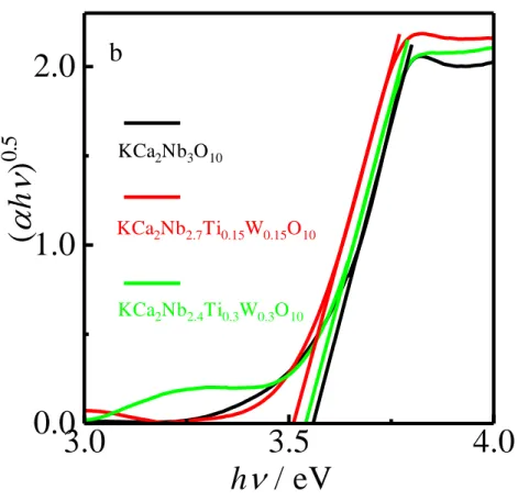
interfacial change transfer (IFCT) emerges or substitution of Ti and W for Nb. Such IFCT can be regarded as a collateral evidence for the existence of the impurity phase. From Tauc plots (Fig. 2-5 (b)) we can see the estimated band gap energies of KCa2Nb3O10, KCa2Nb2.7Ti0.15W0.15O10 and KCa2Nb2.4Ti0.3 W0.3O10 are 3.56, 3.51 and
3.54, respectively. The substitution degrees seem to be small because the estimated band gaps are very similar.
wavelength / nm % R RbLaNb2O7 RbLaNb1.8Ti0.1W0.1O7 RbLaNb1.6Ti0.2W0.2O7 a 300 400 500 600 700 800 0 20 40 60 80 100
31
Figure 2-4 UV-vis for RbLaNb2-2xTixWxO7 and derivatives (a) reflectance
versus wavelength, (b) Tauc plots.
h
/ eV
(
h
)
0
.5
b
RbLaNb2O7 RbLaNb1.8Ti0.1W0.1O7 RbLaNb1.8Ti0.2W0.2O73.0
3.5
4.0
0.0
1.0
2.0
3.0
wavelength / nm R % KCa 2Nb3O10 KCa2Nb2.7Ti0.15W0.15O10 KCa2Nb2.4Ti0.3W0.3O10 a 200 400 600 800 20 40 60 80 10032
Figure 2-5 UV-vis for KCa2Nb3-2xTixWxO10 and derivatives (a) reflectance versus
wavelength, (b) Tauc plots
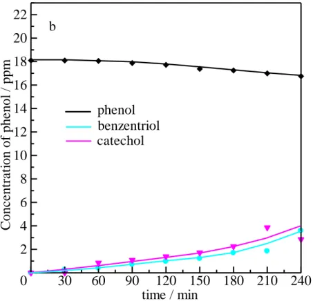
Suppose that after 4 hours experiment, there are three organic species exist in the phenol degraded solution. Fig. 2-6 (a) and (b) shows the relationships between elapsed time and concentration of phenol, benzenetriol and catechol in solution under Xe light irradiation under existence of (a) RbLaNb2O7 and (b) KCa2Nb3O10,
respectively. For RbLaNb2O7, during irradiation for 4 hours by Xe light, the
concentration of phenol slightly decreased. Both concentration of benzenetriol and catechol, which are the intermediate products during the phenol degradation have little increase. At the same time, the concentration of phenol degraded by KCa2Nb3O10 also decreased slightly as shown in Fig. 2-6 (b), which is around 1 ppm
h
/ eV
(
h
)
0
.5
b
KCa2Nb2.7Ti0.15W0.15O10 KCa2Nb2.4Ti0.3W0.3O10 KCa2Nb3O103.0
3.5
4.0
0.0
1.0
2.0
33
decrease than initial concentration. The concentration of benzentriol and catechol increased apparently. It is indicated that the substitution of Ca2+ for La3+ in the A site has no effect for phenol degradation.
time / min
C
o
n
c
e
n
tr
a
ti
o
n
o
f
p
h
e
n
o
l
/
p
p
m
phenol
benzentriol
catechol
a
0
30
60
90
120
150
180
210
240
2
4
6
8
10
12
14
16
18
20
22
34
Figure 2-6 Relationships between elapsed time and concentration of phenol of (a)
RbLaNb2O7 and (b) KCa2Nb3O10
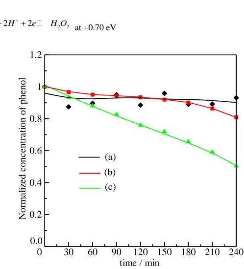
Fig. 2-7 shows the relationships between elapsed time and normalized concentration of phenol. From these plots, the normalized concentration of phenol after the irradiation is 0.8 and 0.5 for RbLaNb1.8Ti0.1W0.1O7 and RbLaNb1.6Ti0.2W0.2O7,
respectively. The photocatalytic reactions accelerate compared with RbLaNb2O7
which the normalized concentration of phenol is 0.9 after irradiation for 4 hours.
These results can be plausibly considered as follows. Valence band composed of O 2p distributes generally at around +3 eV, and the conduction band is probably at around 0 eV or higher estimated from the band gap of 3.2 eV. The substitution of Ti and W results in narrowing the band gap by shifting with 0.1 eV the conduction band
time / min
C
o
n
c
e
n
tr
a
ti
o
n
o
f
p
h
e
n
o
l
/
p
p
m
phenol
benzentriol
catechol
b
0
30
60
90
120
150
180
210
240
2
4
6
8
10
12
14
16
18
20
22
35
downward. Such narrowing band gap may provide acceleration of electron excitation. The hole formed by the excitation of electron can oxidize phenol. On the other hand, the excited electron may be consumed by generation of H2O2 from O2 and H+ at 0.70
eV. The H2O2 can be reduced to H2O with H+ at +1.78 eV. Therefore, the narrowing
of the conduction band by 0.1 eV works efficiently.
+ -2 2 2 H O +2H +2e 2H O at +1.78 eV 2 2 2 2 2 O H e H O at +0.70 eV
Figure 2-7 Relationship between elapsed time and normalized concentration of
phenol in different samples phenol aqueous solutions. (a) RbLaNb2O7, (b)
RbLaNb1.8Ti0.1W0.1O7, (c) RbLaNb1.6Ti0.2W0.2O7
0.0
(a)
(b)
(c)
time / min
N
o
rm
a
li
ze
d
c
o
n
c
e
n
tr
a
ti
o
n
o
f
p
h
e
n
o
l
0
30
60
90
120
150
180
210
240
0.2
0.4
0.6
0.8
1
1.2
36
Fig. 2-8 shows the relationship between elapsed time and normalized concentration of phenol by KCa2Nb3-2xTixWxO10 (x=0,0.15, and 0.3), we can see that
little amount of phenol degraded during 4 hours.
However, smaller improvement can be confirmed in the KCa2Nb3-2xTixWxO10 than
in the RbLaNb2-2xTixWxO7 samples. Some impurity phases in the
KCa2Nb3-2xTixWxO10 indicate no improvement was observed for degradation of
phenol.
Figure 2-8 Relationship between elapsed time and normalized concentration of
phenol in different samples phenol aqueous solutions. (a) KCa2Nb3O10, (b)
KCa2Nb2.7Ti0.15W0.15O10, (c) KCa2Nb2.4Ti0.3W0.3O10
time / min
N
o
rm
a
li
ze
d
c
o
n
c
e
n
tr
a
ti
o
n
o
f
p
h
e
n
o
l
(a)
(b)
(c)
0.0
0
30
60
90
120
150
180
210
240
0.2
0.4
0.6
0.8
1
1.2
37
2.4. Summary
A new series of layered perovskites RbLaNb2-2xTixWxO7 (x=0,0.1, and 0.2
respectively) and KCa2Nb3-2xTixWxO10 (x=0,0.15, and 0.3) have been synthesized.
The XRD results have shown that partial substituted samples has no impurity peaks appeared which indicated that the substitution of Ti and W did not made visible change on the formation of RbLaNb2O7 and derivatives during the solid-stated
reaction process. The photocatalytic activity was evaluated using the degradation of phenol for 4 hours. At last the normalized concentration of phenol are 0.9, 0.8 and 0.5 by RbLaNb2O7, RbLaNb1.8Ti0.1W0.1O7 and RbLaNb1.6Ti0.2W0.2O7 respectively, while
the normalized concentration of phenol of KCa2Nb3O10 and derivatives are very
similar. For the electronic structures, the band gap tends to shrink by the substitution for RbLaNb2-2xTixWxO7. However, KCa2Nb3-2xTixWxO10 has no photocatalytic
activities because of the formation of the impurity phase instead of the substitution. Consequently, the substitution of Ti and W for Nb in RbLaNb2-2xTixWxO7 could
increase the photocatalytic efficiency. In conclusion, substituted of Ti and W for Nb in RbLaNb2-2xTixWxO7 (x= 0.1, 0.2) can apparently improved the photocatalytic
38
References
1. X. Zhang, Y. Zhang, X. Quan and S. Chen, Journal of hazardous materials, 2009, 167, 911-914.
2. C. Chen, W. Ma and J. Zhao, Chemical Society reviews, 2010, 39, 4206-4219. 3. J. Xing, W. Q. Fang, H. J. Zhao and H. G. Yang, Chemistry, an Asian journal,
2012, 7, 642-657.
4. X. Hou, H. Zhang and L. Jiang, Angewandte Chemie, 2012, 51, 5296-5307. 5. K. M. Parida and S. Parija, Solar Energy, 2006, 80, 1048-1054.
6. C. H. Chiou and R. S. Juang, Journal of hazardous materials, 2007, 149, 1-7. 7. G. Zhang, J. Zhou, X. Ding, Y. Hu and J. Xie, Journal of hazardous materials,
2008, 158, 287-292.
8. S. H. Lin, C. H. Chiou, C. K. Chang and R. S. Juang, Journal of
environmental management, 2011, 92, 3098-3104.
9. K. Naeem and F. Ouyang, Journal of Environmental Sciences, 2013, 25, 399-404.
10. Y. A. Shaban, M. A. El Sayed, A. A. El Maradny, R. Al Farawati and M. I. Al Zobidi, Chemosphere, 2013, 91, 307-313.
11. J. R. Reddy, S. Kurra, R. Guje, S. Palla, N. K. Veldurthi, G. Ravi and M. Vithal, Ceramics International, 2015, 41, 2869-2875.
12. S. Yang, J.-S. Gu, H.-Y. Yu, J. Zhou, S.-F. Li, X.-M. Wu and L. Wang,
Separation and Purification Technology, 2011, 83, 157-165.
13. Q. Sun, W. Leng, Z. Li and Y. Xu, Journal of hazardous materials, 2012,
39
14. C. L. Bianchi, S. Gatto, C. Pirola, A. Naldoni, A. Di Michele, G. Cerrato, V. Crocellà and V. Capucci, Applied Catalysis B: Environmental, 2014, 146, 123-130.
15. Y. Sakai, A. Shimanaka, M. Shioi, S. Kato, S. Satokawa, T. Kojima and A. Yamasaki, Catalysis Today, 2015, 241, 2-7.
16. X. Lin, P. Lv, Q. Guan, H. Li, H. Zhai and C. Liu, Applied Surface Science, 2012, 258, 7146-7153.
17. M. Sung, S. Kato, F. Kawanami and M. Sudo, Building and Environment, 2010, 45, 2002-2007.
18. Z. Yi, J. Ye, N. Kikugawa, T. Kako, S. Ouyang, H. Stuart-Williams, H. Yang, J. Cao, W. Luo, Z. Li, Y. Liu and R. L. Withers, Nature materials, 2010, 9, 559-564.
19. J. Liu, Y. Sun, Z. Li, S. Li and J. Zhao, International Journal of Hydrogen
Energy, 2011, 36, 5811-5816.
20. I. Aslam, C. B. Cao, M. Tanveer, M. H. Farooq, W. S. Khan, M. Tahir, F. Idrees and S. Khalid, Rsc Adv, 2015, 5, 6019-6026.
21. Y. Li, J. Wu, Y. Huang, M. Huang and J. Lin, International Journal of
Hydrogen Energy, 2009, 34, 7927-7933.
22. W. N. Xing, L. Ni, X. L. Liu, Y. Y. Luo, Z. Y. Lu, Y. S. Yan and P. W. Huo,
Desalin Water Treat, 2015, 53, 794-805.
23. Y. Huang, Y. Wei, L. Fan, M. Huang, J. Lin and J. Wu, International Journal
of Hydrogen Energy, 2009, 34, 5318-5325.
24. M. A. Bizeto and V. R. L. Constantino, Materials Research Bulletin, 2004, 39, 1729-1736.
40
26. H. Liu, N. Gao, M. Y. Liao and X. S. Fang, Sci Rep-Uk, 2015, 5.
27. L. Hurtado, E. Torres-García, R. Romero, A. Ramírez-Serrano, J. Wood and R. Natividad, Chemical Engineering Journal, 2013, 234, 327-337.
28. Y. Yang, H. Liang, N. Zhu, Y. Zhao, C. Guo and L. Liu, Chemosphere, 2013,
93, 701-707.
29. A. E. Maegli, E. H. Otal, T. Hisatomi, S. Yoon, C. M. Leroy, N. Schäuble, Y. Lu, M. Grätzel and A. Weidenkaff, Energy Procedia, 2012, 22, 61-66.
30. P. Shen, J. C. Lofaro, W. R. Woerner, M. G. White, D. Su and A. Orlov,
Chemical Engineering Journal, 2013, 223, 200-208.
31. Z. Wang, K. Teramura, S. Hosokawa and T. Tanaka, Applied Catalysis B:
Environmental, 2015, 163, 241-247.
32. N. XU, T. TAKEI, A. MIURA and N. KUMADA, J. Ion Exchange, 2014, 25, 242-247.
33. H. Fukuoka, T. Isami and S. Yamanaka, Journal of Solid State Chemistry, 2000, 151, 40-45.
34. Y. Wei, X. Zhang, J. Xu, J. Wang, Y. Huang, L. Fan and J. Wu, Applied
Catalysis B: Environmental, 2014, 147, 920-928.
35. Y. Wei, J. Li, Y. Huang, M. Huang, J. Lin and J. Wu, Solar Energy Materials
and Solar Cells, 2009, 93, 1176-1181.
36. M. Dion, M. Ganne and M.Tournoux, Mater. Res. Bull., 1981, 16, 1429-1435. 37. S. N. Ruddlesden and P. Popper, Acta Cryst., 1957, 10, 538-539.
41
CHAPTER III STUDY ON EFFECT OF PT
HYBRIDIZATION BY PHOTOIRRADIATION
WITH LAYERED NIOBATE PEROVSKITE FOR
PHOTOCATALYTIC BEHAVIOR
3.1. Introduction
During the past few years, environmental conservation has become a worldwide concern [1, 2]. With the continuous increase of industrial activities, the amount of waste generated during industrial processes continues to increase [3-5]. The scientific community is researching effective methods for the removal of chemical waste, among which several contaminants such as phenol and phenolic compounds are of particular interest [6-8]. However, the removal of phenol presents serious challenges because it is neither biodegradable nor can undergo direct photolysis by sunlight; moreover, it cannot be removed by conventional water treatment [9, 10]. Photocatalytic technology, which is valuable for the control of environmental pollution, has been widely investigated [11-14].
Over the past several decades, semiconductor photocatalysis technology has attracted considerable attention for hydrogen generation from water splitting, photoelectrochemical cells, photodegradation of organic pollutants, and photocatalytic conversion of CO2 [15, 16].
42
Photocatalytic technology, which is valuable for the control of environmental pollution, has been widely recognized and investigated [17-19]. Incorporation of a semiconductor in the interlayer region of a lamellar compound is a promising method for enhancing photocatalytic activity of semiconductor, the photogenerated electrons and holes are effectively separated because of the charge transfer from the guest semiconductor to the host layer [20-22].
Meanwhile, semiconductors absorb a fraction of sunlight, mostly UV radiation, depending on their band gap energy [23, 24]. It is well known that electrons which are in the uppermost valence band of a semiconductor jump into the conduction band with photons [8, 25]. In this process, the energy is at least equal to the band gap of the photocatalyst [26]. Valence band holes and conduction band electrons are formed in the process [27]. These photogenerated electrons and holes travel up to the surface of the photocatalyst, where they can participate in chemical reactions [28]. The photogenerated electron–hole pairs react with electron donors and acceptors, creating highly reactive free radicals, which in turn can degrade the contaminant[29, 30]. However, photogenerated electrons and holes can undergo recombination [31, 32]. Hence, our goal was to introduce other cations or anions that can easily capture these electrons or holes so as to prevent their recombination.
Based on this consideration, this study reports the photocatalytic performance of a novel interlayered perovskite by using layered perovskite-structure oxides RbLaNb2O7 and HLaNb2O7 as the host and platinum as the guest. We have previously
43
reported the preparation of partially substituted RbLaNb2O7 by W6+ and Ti4+ for Nb5+
and its phenol degradation activity [33]. owever, the hybridization of RbLaNb2O7
with Pt has not been examined thus far, although Huang et al. have reported a Pt-intercalated layered niobate perovskite and its photocatalytic activity [22]. However, no evidence has been presented for the intercalation of Pt into the interlayer. Hence, we investigated the hybridization of layered niobate perovskite with Pt in detail. Such a structure is expected to effectively inhibit the recombination of charge carriers, thereby enhancing the photocatalytic activity of the semiconductor.
3.2. Experimental section
3.2.1. Materials preparation
Preparation of Layered Perovskite. All reagents were purchased from Kanto
Kagaku Ltd., Japan. The layered perovskite RbLaNb2O7 was synthesized by a
solid-state reaction using an intimate mixture of reagent-grade Rb2CO3, La2O3, and
Nb2O5 in a molar ratio of Rb:La:Nb = 1.25:1:2 as starting materials at 1000 °C in air
for 6 h. An excess of Rb was used to compensate for the loss of Rb by vaporization. Proton exchange of RbLaNb2O7 was conducted 5 times using a 2 M HCl solution at
40 °C for 24 h to afford HLaNb2O7.
Hybridization with Pt. First, 1 g H2PtCl6·6H2O was dissolved in 75.4 mL ethanol
to afford solution (A). Second, 0.5 g perovskite, 0.5 mL solution (A), 9.5 mL methanol, and 40 mL H2O were mixed together and stirred, followed by irradiation
44
with 300 W Xe light at room temperature for 2 h for depositing Pt particles. The product thus obtained was designated as Pt-HLaNb2O7 or Pt-RbLaNb2O7. Third, the
suspension was filtered and washed several times with distilled water for removing the Pt ions remaining on the sample surface. Last, the precipitate was dried at 50 °C to afford the Pt deposit.
3.2.2. Characterization
Structural Analysis. The structures of RbLaNb2O7, HLaNb2O7, Pt-RbLaNb2O7,
and Pt-HLaNb2O7 were examined by X-ray diffraction (XRD, RINT-2000, Rigaku)
with monochromated CuKα radiation. The chemical compositions of the samples were measured by X-ray fluorescence (XRF, ZSX Primus II, Rigaku). The particle shape of these samples were observed by field-emission scanning electron microscope (FE-SEM, JSM-6500F, JEOL). The chemical states of these samples were measured by X-ray photoelectron spectroscopy (XPS, Kratos Axis-Ultima, Shimadzu). The electronic structures of these samples were examined for optical band gap by UV–vis spectroscopy (V-550, Jasco), and for calculation by first-principles density functional theory (DFT, Vasp 5.2). The calculations were conducted by projector-augmented wave (PAW) potentials. The calculations were performed using the ab-initio total-energy and molecular-dynamics program VASP (Vienna ab-initio simulation program) developed at the Institut für Materialphysik of the Universität Wien [34, 35].
45
The hybrids with Pt were analyzed by synchrotron XRD (SXRD) using a Debye– Scherrer camera at BL02B2 in Spring-8. The sample was filled into a borosilicate glass tube having a radius of 0.2 mm. The X-ray wavelength used was 0.496071 Å, as determined using CeO2 as the reference. The refinement of the crystal structure was
conducted by Rietan-FP [36].
Photocatalytic Test. Photocatalytic activity was evaluated by phenol degradation.
For considering practical applications, Xe light was used as the irradiation source. First, a 20 ppm aqueous phenol solution was prepared using ultrapure water; second, the sample was dispersed into this phenol solution at a concentration of 3 g/L. Third, the solution was stirred under dark conditions (no visible light irradiation) for 1 h to examine the adsorption balance of phenol. After 1 h, the solution was photoirradiated by ultraviolet light from a 300 W Xe lamp (UXR-300DU, Ushio Inc.) while being stirred continuously. Aliquots of 2 mL were extracted at 30, 60, 90, 120, 150, 180, 210, and 240 min of the elapsed time. The concentration of phenol in solution was measured by high-performance liquid chromatography (CO-2065, Jasco) using an ODS column.
3.3. Results and discussion
Characterization of Prepared RbLaNb2O7 and HLaNb2O7 and Hybridization
with Pt Photocatalysts. Fig. 3-1 shows the crystal structure of RbLaNb2O7: a
46
NbO6 octahedra sheets with La ions in the interstices of the NbO6 octahedra.
According to the diffraction line at 2θ = 7.94° in the XRD data with monochromated CuKα radiation, the interlayer distance of RbLaNb2O7 is 1.11 nm.
Figure 3-1 Crystal structure of RbLaNb2O7.
Fig. 3-2 shows the powder XRD patterns of (a) RbLaNb2O7, (b) Pt-RbLaNb2O7, (c)
HLaNb2O7, and (d) Pt-HLaNb2O7. From these patterns, the samples appeared to
contain single phases of RbLaNb2O7 or HLaNb2O7, with interlayer distances of approximately 1.1 nm. The interlayer distance slightly decreases by protonation and does not change by Pt deposition. However, the diffraction patterns, especially intensity ratios, apparently change by protonation because of the large decrease of the electrons within the interlayer space. Such a large decrease provides a small atomic scattering factor, which leads to a small crystal structure factor. For the hybrids with Pt, the existence of Pt-related compounds cannot be observed in these patterns.
Perovskite
←interlayer cation; A’
←cation A ←BX6 octahedra
47
Figure 3-2 XRD patterns of (a) RbLaNb2O7, (b) Pt-RbLaNb2O7, (c) HLaNb2O7, and
(d) Pt-HLaNb2O7.
For determining the amount of Pt in compounds, the XRF of the samples was measured. Table 3-1 shows the results. These results show that Rb is absent in the protonated sample and Pt-HLaNb2O7, which is attributed to successful protonation.
Moreover, after Pt deposition, only marginal amounts of Pt exist in Pt-RbLaNb2O7
and Pt-HLaNb2O7. Meanwhile, the amount of Rb decreases in Pt-RbLaNb2O7.
H2PtCl6·6H2O is supposed to be an acid, which can react with RbLaNb2O7. After ion
exchange by H2PtCl6 to form RbCl, a part of Rb is consumed by ion exchange with
protons, and the Rb/La ratio decreases.
Table 3-1 Ratio of Pt/La and Rb/La in compounds.
Cu
/ degree
In
te
n
si
ty
(
a.
u
.)
a
b
c
d
10
20
30
40
50
48
RbLaNb2O7 Pt-RbLaNb2O7 HLaNb2O7 Pt-HLaNb 2O7
Pt/La 0.000 0.013 0.000 0.011
Rb/La 1.040 0.934 0.000 0.000
Fig. 3-3 shows FE-SEM micrographs of (a) RbLaNb2O7, (b) Pt-RbLaNb2O7, (c)
HLaNb2O7, and (d) Pt-HLaNb2O7. The particle shapes are seemed to be formless for
all samples. These micrographs cannot confirm the Pt nanoparticles on outer surface of the samples. The mean particle sizes of all samples are similar from 200nm to 500nm. Such similar size may be due to no change of shape by the protonation and/or hybridization of Pt processes. In consistence with the SEM observation, we also estimate the specific surface areas of all samples based on the corresponding geometric shape, particle size (from FESEM), and the real density. The specific surface area values are around1-3 m2/g.
49
Figure 3-3 FE-SEM micrographs of (a) RbLaNb2O7, (b) Pt-RbLaNb2O7, (c)
HLaNb2O7 and (d) Pt-HLaNb2O7.
50
Figure 3-4 XPS spectra of (I) both Pt-included samples, (II) Pt-RbLaNb2O7, and (III)
expanded Pt-HLaNb2O7.
XPS was employed for analyzing the chemical state of Pt in the samples. Fig. 3-4 shows the high-resolution XPS spectra of Pt 4f in Pt-RbLaNb2O7 and Pt-HLaNb2O7.
These spectra seem to be composed of two states of Pt for both hybrids. In Fig. 3-4(II) Pt-RbLaNb2O7, the binding energies of both states for Pt 4f7/2 are 70.4 eV and 71.8
eV, while those for Pt 4f5/2 are 73.8 eV and 75.1 eV, respectively. Binding energies of
approximately 70.4 eV and 73.8 eV are attributed to the Pt metal, while the other
80 78 76 74 72 70 Pt 4f I nte nsi ty (a . u.) Binding Energy / eV Pt-RbLaNb2O7 Pt-HLaNab2O7 I 80 78 76 74 72 70 700 800 900 1000 1100 1200 1300 1400 71.8 eV I n ten s it y / co u n ts Binding Energy / eV 4f7/2 70.4 eV 4f5/2 73.8 eV Pt 4f II 75.1 eV Pt-RbLaNb2O7 80 78 76 74 72 70 680 700 720 740 760 780 800 820 4f7/2 73.6 eV 4f 5/2 74.2 eV I n ten s it y / co u n ts Binding Energy / eV 4f 5/2 77.0 eV 4f 7/2 70.8 eV III Pt-HLaNb2O7 Pt 4f
51
peaks at approximately 71.8 eV and 75.1 eV are attributed to the platinum oxide layer, which covered the surface of Pt metal particles. This spectrum apparently indicates that Pt metal particles are located on the RbLaNb2O7 surface in Pt-RbLaNb2O7. On
the other hand, in Fig. 3-4(III) Pt-HLaNb2O7, the trimodal peak can be split into four
peaks, as can be observed in the spectrum. The binding energies of 70.8 eV and 74.2 eV are attributed to Pt 4f7/2 and Pt 4f5/2 of Pt metal, respectively. On the other hand,
the other peaks with binding energies of approximately 73.6 eV (4f7/2) and 77.0 eV
(4f5/2) are attributed to Pt2+. By comparing Pt-RbLaNb2O7 and Pt-HLaNb2O7, the peak
intensity for the Pt metal drastically decreases concurrently, and the peak of the surface oxide layer of Pt metal disappears. By contrast, peaks for Pt2+ are observed in Pt-HLaNb2O7, which are not observed in Fig. 3-4(II). In addition, the total intensity of
Pt steeply decreases. This small intensity for Pt-HLaNb2O7 suggests that Pt is absent
on the surface of the niobate particles. These changes in the spectra confirm that Pt possibly exists as metal particles on the surface of the niobate particles in the case of Pt-RbLaNb2O7 and as cations within the interlayer space in the case of Pt-HLaNb2O7.
At one glance, interlayer Pt2+ is interesting because Pt exists as an anionic complex, PtCl62−, in H2PtCl6. Harada [37, 38] has reported that when PtCl62− ionic complexes in
an ethanol–water solution are photoirradiated by UV light, Pt4+ is reduced to Pt0 metal particles via Pt2+, as shown in eq 3-1.
𝑃𝑡𝐶𝑙62− → 𝑃𝑡𝐶𝑙 4
52
During the process, PtCl42− can be temporarily dissociated to form Pt2+ before
forming Pt0 (metallic state). The HLaNb2O7 sample still exhibits competent proton
exchange and can trap temporal Pt2+ by ion exchange during UV irradiation. However, the layered perovskite RbLaNb2O7 can barely trap Pt2+ because of the lack of an
exchangeable proton. The ion exchangeability for a proton is probably caused by high molar conductance. The conductance values of H+ and Rb+ are approximately 3.5 10−2 and 7.8 10−3 S m2/mol, respectively. High conductance can facilitate high ion mobility, and protonated samples may exhibit good ion exchangeability.
Further, the samples hybridized with Pt are examined by SXRD. For Pt-RbLaNb2O7, an approximately 5 mass% RbCl phase is observed as an impurity.
However, the diffraction lines of 111 and 200 for Pt metal (d111 = 2.26 and d200 = 1.95,
respectively) cannot be detected because of overlap with some peaks of the mother phase RbLaNb2O7. In the case of Pt-HLaNb2O7, most of the peaks are identified as
HLaNb2O7. Fig. 3-5 shows the refined SXRD pattern of Pt-HLaNb2O7. The main
phase can be refined as HLaNb2O7 (𝐹𝑚3̅𝑚, a = 5.4810(4), b = 20.9305(0), c =
5.4861(8)). The refinement result confirms that a very small amount of Pt metal exists within the hybrid. However, it is difficult to ascertain this amount caused by the very weak diffraction intensity. Then, we evaluated the Pt cation within the interlayer space by the 112, 211, 042, and 240 diffraction lines of the Pt-HLaNb2O7 phase. Fig.
3-6 shows the expanded SXRD patterns of HLaNb2O7 and Pt-HLaNb2O7 and the
53
presence of Pt cations within the interlayer space apparently increases the intensities of the abovementioned diffractions. From these measured patterns, an apparent peak emerges only in the case of Pt-HLaNb2O7, which possibly results from Pt2+ within the
interlayer space. From SXRD and XPS data, we conclude that Pt exists not only outside of particle as metal state but also within the interlayer space as Pt2+ for Pt-HLaNb2O7.
54
Figure 3-5 Refined SXRD pattern of Pt-HLaNb2O7.
R
w p=
2
.4
9
%
R
p=
1
.6
8
%
S
=
3
.1
0
Int
en
sit
y /
co
unt
s
2
/
d
e
g
re
e
1
0
2
0
3
0
4
0
5
0
6
0
0
2
0
0
0
0
4
0
0
0
0
6
0
0
0
0
8
0
0
0
0
55
Figure 3-6 Expanded SXRD patterns of HLaNb2O7 and Pt-HLaNb2O7 as well as
calculated patterns of HLaNb2O7 and Pt0.5Nb2O7.
Band Gap and DOS Calculation of Photocatalysts. Fig. 3-7 shows the
comparison of the UV–visible spectra of (a) RbLaNb2O7, (b) Pt-RbLaNb2O7, (c)
HLaNb2O7, and (d) Pt-HLaNb2O7. Sharp absorption edges are observed at
approximately 330–380 nm. Meanwhile, (b) Pt-RbLaNb2O7 and (d) Pt-HLaNb2O7
exhibit more visible light absorption ability as compared to (a) and (c), which did not
(211) (112) (042)(240)