Doctoral Dissertation
MAPPING FUNCTIONS THAT
MAXIMIZE MUTUAL INFORMATION FOR DECODING LDPC CODES
FRANCISCO JAVIER CUADROS ROMERO
Supervisor: Professor Brian Michael Kurkoski School of Information Science
Japan Advanced Institute of Science and Technology
March, 2017
Reviewed by
Professor Mineo Kaneko Professor Hideki Yagi Professor Dirk Wubben Professor Tadashi Matsumoto
Abstract
Low-density parity-check (LDPC) codes have been reported to perform close to the channel capacity. LDPC decoders and channel quantization algorithms are usually implemented using floating point simulations in Matlab/C or another programming languages. Once these algorithms are carefully optimized, the next step is to carry out their correspond- ing hardware implementation in a very-large-scale integrated (VLSI) cir- cuit. In such implementation, LDPC decoders and channel quantization algorithms are converted to a fixed-point representation. For example, the offset min-sum (OMS) algorithm for decoding LDPC codes uses real- valued operations: addition, min. But the channel and decoder messages are usually quantized to a bit width of 4 to 7 bits, depending on the perfor- mance/complexity tradeoff. In this research, floating-point algorithms are not used. Instead, the central method is “direct design” of VLSI circuits for LDPC decoders and channel quantizers.
The objective of this research is to design LDPC decoder schemes and channel quantizers that can be implemented in VLSI circuits. For LDPC decoders, the goal is designs that achieve high throughput (a few iterations) and low gate count (a few bits per message). For channel quantization, the goal is to find an optimal quantization scheme, for a fixed bit width, even when the error distribution model is based only on sample data.
In this dissertation, we have developed a technique where the LDPC decoders and channel quantization implementations, including quantiza- tion of messages, are designed using only the probability distribution from the channel. Given a probability distribution, our method designs a lookup table (LUT) that maximizes mutual information, and LUTs are imple- mented directly in VLSI circuits. This is the “max-LUT method”.
The proposed lookup tables are sometimes referred as mapping func- tions. The mapping functions we propose are used for channel quantiza- tion and for message-passing decoding of LDPC codes. These mapping functions are not derived from belief-propagation decoding or one of its approximations, instead, the decoding mapping functions are based on a channel quantizer that maximizes mutual information. More precisely, the construction technique is a systematic method which uses an optimal
quantizer at each step of density evolution to generate message-passing decoding mappings.
In a simple manner, the design of LDPC decoders by maximization of mutual information is analogous to finding non-uniform quantization schemes where the quantization can vary with each iteration.
The proposed decoding mapping functions are particularly well suited for data storage applications, because they can be designed from non- parametric and irregular noise distributions. Though finite-length simula- tions show that the proposed decoding mappings functions present good performance for a variety of code rates.
Numerical results show that using 4 bits per message and a few itera- tions (10–20 iterations) are sufficient to approach the error-rate decoding performance of full (without quantization) sum-product algorithm (SPA), less than 5–7 bits per message typically needed to perform around 1 dB away from the error-rate decoding performance of full SPA.
Another result of this research is that the construction technique for the mapping functions is flexible since it can generate maps for arbitrary number of bits per message, and can be applied to arbitrary binary-input memoryless channels.
Keywords: LDPC decoding, mapping functions, lookup tables, quan- tization, sum-product algorithm.
Acknowledgments
First of all, I wish to thank to all committee members who kindly accepted to be part of it. Undoubtedly, Prof. Brian Kurkoski is the first person whom I really want to show my gratitude to. His guidance and support throughout the time of my dissertation have an incalculable value. This dissertation brings me back memories of the days when I was an exchange master student in the University of Electro-Communications (UEC) in Tokyo. I was really lucky to get in touch with Prof. Brian M. Kurkoski for the very first time. I remember he accepted me in his lab knowing that my background in information theory and coding theory was really low.
I used to be an image processing guy, but not anymore. Other professor to whom I would like to thank is Prof. Hideki Yagi who took care of me when Prof. Brian left UEC to work in JAIST. I remember that he always had time to solve my questions in a simple and clear way. Later when I became Ph. D. student at JAIST, I was lucky again because I had the chance to meet Prof. Tad Matsumoto who always has the tricky questions that make me study harder.
I would like to thank Dr. Khoirul Anwar, assistant professor in our laboratory, for his selfless help. Also, I would like to say thank you to all my lab colleagues who already left as well as those who still stay there, Pen-Shun Lu, Hui Zhou, Ade Irawan, Xin He, Shen Qian, Kun Wu, Muhammad Reza Kahar Aziz, Ricardo Antonio Parrao Hernandez, Erick Garcia Alvarez, Ryouta Sekiya, Mohammad Nur Hasan and Fan Zhou for their kind help and friendship.
Before to finish, I want to thank to the Consejo Nacional de Ciencia y Tecnologia – CONACYT (the Mexican National Council for Science and Technology) because it supported part of my Ph. D. studies in JAIST.
Moreover, I want to thank all members of the university staff who managed my living in JAIST well so that I can concentrate to the research work. Finally, thanks to my parents who are thousands miles away in Mexico. Their spiritual support will be treasured forever in my deep heart.
Contents
Abstract i
Acknowledgments iii
List of symbols vi
Abbreviations xiv
List of Figures xix
List of Tables xxiii
1 Introduction 1
1.1 Transmission and storage of data . . . 1
1.2 LDPC codes and their key properties . . . 4
1.3 Decoding of LDPC codes . . . 5
1.4 Discrete LDPC decoding algorithms . . . 6
1.5 Proposed technique for LDPC decoding . . . 8
1.6 Summary of contributions . . . 11
1.7 Dissertation outline . . . 13
2 Preliminaries 14 2.1 Performance measures . . . 14
2.2 Channel capacity . . . 15
2.3 Channel capacity for useful DMCs . . . 16
2.3.1 The binary symmetric channel . . . 17
2.3.2 The binary-input AWGN channel . . . 17
2.4 Representation of LDPC codes . . . 20
2.4.1 Matrix representation . . . 21
2.4.2 Graphical representation . . . 21
2.5 The Gallager sum-product algorithm . . . 22
2.6 Summary . . . 25
3 Max-LUT method: Maximizing mutual information 26
3.1 Factorization of a global function . . . 26
3.2 Recursive determination of marginals . . . 29
3.3 Message-passing algorithm in cycle-free factor graphs . . . 32
3.4 Message-passing algorithm in factor graphs with cycles . . 33
3.5 Message-passing decoding and its variations . . . 36
3.6 Discretized message-passing decoding . . . 38
3.6.1 Discretized message-passing decoding on a Tanner graph . . . 38
3.6.2 Discretized message-passing decoding on a decom- posed Tanner graph . . . 40
3.7 Optimal quantizer that maximizes mutual information . . 43
3.7.1 Partial mutual information . . . 45
3.7.2 Quantization algorithm . . . 45
3.8 Max-LUT method . . . 47
3.9 Constructing a decoding mapping function via max-LUT method . . . 48
3.10 Summary . . . 50
4 Discretized density evolution 52 4.1 Density evolution . . . 52
4.2 Density evolution for regular LDPC codes via Gaussian aproximation . . . 53
4.3 Proposed discretized density evolution algorithm . . . 57
4.3.1 Discretized density evolution algorithm with quan- tization . . . 58
4.3.2 Discretized density evolution algorithm in a decom- posed Tanner graph . . . 60
4.4 Decoding thresholds for BI-AWGNC . . . 63
4.5 Lookup table arrangement and its representation in a tree 68 4.6 Summary . . . 70
5 Finite-length LDPC decoding via mapping functions 71 5.1 Finite-length results for LDPC codes . . . 72
5.1.1 Simulation results for low rate codes . . . 73
5.1.2 Simulation results for medium code rates . . . 76
5.1.3 Simulation results for high rate codes . . . 80
5.2 Summary . . . 84
6 Conclusions and future work 86 6.1 Conclusions . . . 86 6.2 Future work . . . 87
Appendix A 88
Bibliography 95
Publications 100
List of symbols
Kcode Amount of incoming data bits to the channel encoder.
N Length of the code. Size of an outgoing codeword from the channel encoder.
R Rate of the code.
u Binary codeword of length N. ˆ
u Estimated binary codeword by the decoder of length N. H Parity-check matrix.
M Number of rows in a parity-check matrix H.
i Indicates a row in a parity-check matrix H.
j Indicates a bit position inside of a codeword u or estimated codeword ˆ
u. It is also used to indicate a column in a parity-check matrix H.
hi,j Value of the element in the row i and column j of a parity-check matrix H.
dv Degree of the variable node. Number of ones in a column of the parity- check matrix.
dc Degree of the check node. Number of ones in a row of the parity-check matrix.
dmin Minimum distance of a code.
K Number of quantization levels.
uj Encoded bit belonging to the codewordu.
ˆ
uj Estimated decoded bit belonging to an estimated codeword u. Thisˆ variable is also used in Chapter 3 as a generic binary random variable of a generic function f.
yj Indicates thejth output from a binary-input discrete memoryless chan- nel.
ˆ
yj Indicates the binary jth output from a binary-input discrete memory- less channel.
ˆ
uj Decoded bit belonging to the estimated codeword ˆu.
Pb Bit-error probability.
Pcw Codeword-error probability.
X A discrete random variable. Input to a binary-input discrete memory- less channel.
X Alphabet for the discrete random variable X.
Y A discrete random variable. Output of a binary-input discrete memo- ryless channel.
Y Alphabet for the discrete random variableY. H(·) Entropy of a discrete random variable.
H(·|·) Conditional entropy between two discrete random variables.
p(·) Probability mass function.
p(·|·) Conditional probability mass function.
p(·,·) Joint probability of two variables.
I(·;·) Mutual information between two discrete random variables.
C Channel capacity.
CBSC Channel capacity for the binary symmetric channel (BSC).
h(·) Binary entropy function.
ε Cross-over probability in a binary symmetric channel (BSC).
x Vector of lengthN which is used as the input to a binary-input discrete memoryless channel.
y Binary decoded vector of length N.
xj Indicates a mapping point for the BPSK modulation i.e. xj ∈ {−1,1}.
Eb Energy per message bit.
Ec Energy per transmitted coded bit.
a It is equal to the square root of the energy per transmitted coded bit.
Ec Energy per transmitted coded bit.
σ Standard deviation for a BI-AWGNC.
σ2 Variance for a BI-AWGNC.
$ Gaussian noise vector of length N.
$j jth Gaussian noise value of the vector $.
N0 Noise espectral density.
Eb/N0 Bit signal-to-noise ratio.
R Set of the real numbers.
E Expected value of a discrete random variable.
N(0, σ2) Gaussian distribution with mean 0 and variance σ2.
CBI−AW GN C Channel capacity for a binary-input additive white Gaussian noise channel (BI-AWGNC).
δ Arbitrary small value.
Qf unc(·) Q-function.
N(i) Set of indices that are nonzero elements in the rowiof a parity-check matrix H.
M(j) Set of indices that are nonzero elements in the columnj of a parity- check matrix H.
N(i)\j Set of indices that are nonzero elements in the row i of a parity- check matrix Hwithout the index j.
M(j)\i Set of indices that are nonzero elements in the column j of a parity-check matrix H without the index i.
Vj→i Decoder message from the variable node j to the check nodei.
Li→j Decoder message from the check nodei to the variable node j.
Lj Log-likelihood ratio of thejth bit.
f Generic function used in Chapter 3.
P
∼{·} Variables inside of the braces indicate the variables not being summed over.
g Generic global function used in Chapter 3.
r Generic binary ransom variable used in Chapter 3.
W Number of factors of a global function g or f.
w A specific factor of a global function g or f.
gw(r, . . .) Factorw of a global function g with root r.
Ccode A linear block code.
(p0, p1) Vector of probabilities of a binary random variable which represent a decoder message.
(q0, q1) Vector of probabilities of a binary random variable which represent a decoder message.
Φ Mapping function or lookup table that performs the check node update.
φ Mapping function or lookup table that performs part of the check node update in a decomposed check node.
Ψ Mapping function or lookup table that performs the variable node up- date.
ψ Mapping function or lookup table that performs part of the variable node update in a decomposed check node.
Γ Mapping function or lookup table that performs the hard decision in a variable node.
γ Mapping function or lookup table that performs part of the hard deci- sion in a decomposed variable node.
Λ{·} Parametrization used in a message-passing algorithm.
Ω Generic variable used in Chapter 3 to explain an approximation of the variable node update.
d Degree of a node.
` Number of iteration.
Z Channel message.
Z Alphabet for the channel message.
L Check-to-variable node message.
L Alphabet for the check-to-variable node messages.
S Message between a pair of mapping functions φin a decomposed check node.
S Alphabet for the interconnecting messages S in a decomposed check node.
V Variable-to-check node message.
V Alphabet for the variable-to-check node messages.
T Message between a pair of mapping functionsψ in a decomposed vari- able node.
T Alphabet for the interconnecting messagesT in a decomposed variable node.
Q A quantizer.
Q Set of all possible quantizers.
Q∗ Optimal quantizer that maximizes mutual information.
a Boundary in a finely quantized channel output.
a∗ Optimal boundary that maximizes mutual information.
px Input distribution of the channel input X.
pz|x Transition probability between the input to the channel x and the quantizer output z.
Qz|y Transition probability between the quantizer outputzand the output of the channel y, i.e. Qz|y ∈ {0,1}.
A Subset of channel outputs y.
ι Partial mutual information.
ρz(y) State of the quantization algorithm that represents the maximum partial mutual information when 1 to yvalues ofY are quantized to 1 to z values of Z.
hz(a) Used to save a local decision during the quantization algorithm that finds the optimal quantizer Q∗.
α∗ Decoding threshold computed by the density evolution algorithm.
L0 Initial channel message.
m0 Mean of the initial channel messageL0. m(`) Mean of the variable-to-check message Vj→i. n(`) Mean of the check-to-variable message Li→j. p(·) Probability density function.
r(0)(x0, y0) Initial channel transition probability at iteration `.
t Generic probability distribution used during the DEA.
t˜Generic joint probability distribution used during the DEA.
r(`) Probability distribution for V at iteration`.
˜
r(`) Joint distribution distribution of the incoming messages to the vari- able node at iteration `.
l(`) Probability distribution forL at iteration`.
˜l(`) Joint distribution distribution of the incoming messages to the check node at iteration `.
fc Function for the check node (modulo two addition).
Q(`)c Optimal quantizer that maximizes mutual information at the itera- tion ` in the check node.
fv Function for the variable node (equality).
Q(`)v Optimal quantizer that maximizes mutual information at the itera- tion ` in the variable node.
⊗ Kronecker product.
K Number of quantization levels.
y0 Concatenation of the incoming messages to a node.
Abbreviations
ARQ Automatic request-for-repeat BER Bit-error rate
BI-AWGNC Binary-input additive white Gaussian noise channel BP Belief propagation
BPSK Binary phase-shift keying
Blue-ray Digital optical data storage format BSC Binary symmetric channel
CD Compact disc dB Decibel
DMC Discrete memoryless channels
DVD Digital versatile disc or digital video disc FAID Finite alphabet iterative decoder
FEC Forward-error-correction FER Frame-error rate
FPGA Field-programmable gate array IC Integrated circuit
IEEE Institute of electrical and electronics engineers LD Likelihood difference
LDPC Low-density parity-check LLR Log-likelihood ratio
LUT Lookup table
max-LUT Lookup table that maximizes mutual information MD Mapping decoder
MPF Marginalize-product-of-function MS Min-sum
NQBPA Non-uniform quantized belief propagation algorithm OMS Offset min-sum
pdf Probability density function PLR Parity likelihood ratio
RS-LDPC Reed-Solomon based LDPC SNR Signal-to-noise ratio
SPA Sum-product algorithm SSD Solid-state drive
USB Universal serial bus UTP Unshielded twisted-pair VLSI Very-large-scale integration WER Word-error rate
Wi-Fi It is a trademark of the Wi-Fi Alliance
WiMax Worldwide interoperability for microwave access
List of Figures
1.1 Block diagram of general digital communication system. . 2 1.2 Graphical representation of a parity-check matrix H by a
Tanner graph. Edges interconnecting nodes of different types are drawn wherever there is a one in the matrix H. . 4 2.1 Diagram and channel capacity plot for the binary symmet-
ric channel. . . 17 2.2 Block diagram that represents the transmission of a binary
codeword u through the BI-AWGNC. Coding a decoding are assumed to be carried out by LDPC codes. . . 18 2.3 Plotting soft-decision and hard-decision capacity curves for
the BI-AWGNC, along with the curve for the Shannon ca- pacity. . . 19 2.4 Tanner graph for the parity-check matrix H in (2.26) . . . 22 3.1 Representation of a bipartite tree with two factors (sub-
trees) closed by ellipses (left hand side). Tanner graph of a code Ccode with its corresponding check node equations (right hand side). . . 28 3.2 Initialization conditions and node operations of the message-
passing algorithm on a bipartite tree. . . 34 3.3 A factor graph representation of a linear block code (left).
Tanner graph representation of a linear block code empha- sizing an existing 4-cycle by dashed lines (right) . . . 35
3.4 Decomposition of the variable node and check node into a set of two-input mapping functions (or two-input lookup tables). (a) Check node update operation. (b) Variable node update operation. (c) Hard decision operation on the variable node. (d) Decomposition of the check node update operation Ψ(`)c into the set of two-input mapping functions ψ1(`), . . . , ψ(`)d
c−2. (e) Decomposition of the variable node up- date operation Φ(`)v into the set of two-input mapping func- tionsφ(`)1 , . . . , φ(`)d
v−1. (f) Decomposition of the hard decision operation Γ(`)v into the set of two-input mapping functions γ1(`), . . . , γd(`)
v. . . 39 3.5 Required memory locations to implement both the decod-
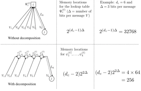
ing lookup table Ψ(`)c and its decomposition ψ1(`), . . . , ψ4(`). This example consider a check node with degreedc= 6 and incoming messages V with a resolution of ∆ = 3 bits. . . . 41 3.6 Overview of the designing process for the mapping func-
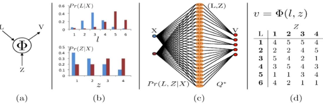
tion Φ. (a) degree-2 LDPC variable node with inputs L and Z and output V. (b) Input distributions Pr(L|X) and Pr(Z|X). (c) Joint distribution Pr(L, Z|X) quantized to five-valued variable V using the optimal quantizer Q∗ which maximizes the mutual information between X and V. (d) The resulting lookup table corresponding to Q∗. This lookup table computesV = Φ(L, Z) to maximize mu- tual information. . . 48 4.1 Evolution of the Gaussian pdfs for the variable-to-check
message Vj→i(`). Different values of Eb/N0 are used. . . 55 4.2 Behavior of the mean µ(`) as a function of the number of
iterations `. . . 56 4.3 Noise decoding thresholds for a regular (3,6)-LDPC code
with rate 1/2 and using different number of levels K for the decoder message quantization. The term log2(K) is the number of bits to represent the decoder messages while log2(|Z|) is the number of bits to represent the BI-AWGNC message. . . 64
4.4 Noise decoding thresholds for a (4,6) regular LDPC code with rate 1/3 and using different number of levels K for the decoder message quantization. The term log2(K) is the number of bits to represent the decoder messages while log2(|Z|) is the number of bits to represent the BI-AWGNC message. . . 67 4.5 Tree representation of the implementation of a hard deci-
sion operation using lookup table. The node has six inputs including the channel message. . . 69 5.1 BER and WER results for the proposed decoding mapping
functions, and sum-product algorithm. Parameters of the code: dv = 4, dc = 5, R = 0.2, and N = 6535. The maxi- mum number of Iterations was set to 25. The numbers next to the curves represent the average number of iterations for each simulation point. . . 74 5.2 BER and WER results for the proposed decoding mapping
functions, and sum-product algorithm. Parameters of the code: dv = 4, dc = 6, R = 0.33, and N = 816. The maxi- mum number of Iterations was set to 25. The numbers next to the curves represent the average number of iterations for each simulation point. . . 75 5.3 BER and WER results for the proposed decoding mapping
functions, and sum-product algorithm. Parameters of the code: dv = 3, dc = 6, R = 0.5, and N = 2640. The maxi- mum number of Iterations was set to 25. The numbers next to the curves represent the average number of iterations for each simulation point. . . 77 5.4 BER results for the proposed decoding mapping functions,
and sum-product algorithm. Parameters of the code: dv = 4, dc = 8, R = 0.5, and N = 10456. The maximum num- ber of Iterations was set to 30. The numbers next to the curves represent the average number of iterations for each simulation point. . . 78 5.5 Word-error rate results for SPA using floating point num-
bers, FAIDs using 7 levels of quantization and the decod- ing mappings (max-LUT) using 3 and 4 bits per message.
A regular (dv = 3, dc = 12)-LDPC code was used with R = 0.75, block length N = 2388 and a maximum of 60 iterations. . . 79
5.6 BER and WER results for the proposed decoding mapping functions, and sum-product algorithm. Parameters of the code: dv = 6, dc= 32,R = 0.84, andN = 2048. The maxi- mum number of Iterations was set to 30. The numbers next to the curves represent the average number of iterations for each simulation point. . . 81 5.7 BER and WER results for the proposed decoding mapping
functions, and sum-product algorithm. Parameters of the code: dv = 4, dc= 36,R = 0.89, andN = 1998. The maxi- mum number of Iterations was set to 30. The numbers next to the curves represent the average number of iterations for each simulation point. . . 82 5.8 BER and WER results for the proposed decoding mapping
functions, and sum-product algorithm. Parameters of the code: dv = 4, dc= 69,R = 0.94, andN = 8970. The maxi- mum number of Iterations was set to 20. The numbers next to the curves represent the average number of iterations for each simulation point. . . 83
List of Tables
1.1 List of various proposed discrete message-passing decoding algorithms using a certain number of bits to represent each received coded bit beloging to a received noisy codeword.
PLR: Parity likelihood ratio, MS: min-sum, NQBPA: non- uniform quantized belief propagation algorithm, SPA: sum- product algorithm, OMS: offset min-sum, FAID: Finite al- phabet iterative decoder, MD: mapping decoder, max-LUT:
lookup table that maximizes mutual information, BSC: Bi- nary symmetric channel, BI-AWGNC: Binary-input addi- tive white Gaussian noise channel. . . 9 4.1 Noise decoding thresholds for a regular (dv = 3, dc = 6)-
LDPC with rate R = 1/2 over a BI-AWGNC using differ- ent quantization levels K and |Z| for the decoder message and the channel message respectively. The term log2(K) is the number of bits to represent the decoder message, while log2(|Z|) is the number of bits to represent the channel message. . . 65 4.2 Comparison for different arrangements (trees) to implement
a hard decision operation with six inputs including the channel message. The decoding thresholds σ∗ were com- puted considering that the incoming messages have a reso- lution of 3 bits. . . 69 5.1 Simulation parameters for the proposed decoding mapping
functions. . . 73 5.2 Noise decoding thresholds for channel and decoder message
quantization using 3 and 4 bits per message. . . 73
5.3 Noise decoding thresholds for channel and decoder message quantization using 3 and 4 bits per message. In the case of the (dv = 3, dc= 12)-LDPC code, its variance noise thresh- olds σ2 were used to calculate the corresponding crossover probabilities ε for the BSC via the Q-function. . . 76 5.4 Decoding thresholds for channel and decoder message quan-
tization using 3 and 4 bits per message. . . 80 A.1 Noise decoding thresholds for a regular (dv = 2, dc = 40)-
LDPC with rateR = 19/20 over a BI-AWGNC using differ- ent quantization levels K and |Z| for the decoder message and the channel message respectively. The term log2(K) is the number of bits to represent the decoder message, while log2(|Z|) is the number of bits to represent the channel message. . . 89 A.2 Noise decoding thresholds for a regular (dv = 3, dc = 4)-
LDPC with rate R = 1/4 over a BI-AWGNC using differ- ent quantization levels K and |Z| for the decoder message and the channel message respectively. The term log2(K) is the number of bits to represent the decoder message, while log2(|Z|) is the number of bits to represent the channel message. . . 89 A.3 Noise decoding thresholds for a regular (dv = 3, dc = 6)-
LDPC with rate R = 1/2 over a BI-AWGNC using differ- ent quantization levels K and |Z| for the decoder message and the channel message respectively. The term log2(K) is the number of bits to represent the decoder message, while log2(|Z|) is the number of bits to represent the channel message. . . 90 A.4 Noise decoding thresholds for a regular (dv = 4, dc = 5)-
LDPC with rate R = 1/5 over a BI-AWGNC using differ- ent quantization levels K and |Z| for the decoder message and the channel message respectively. The term log2(K) is the number of bits to represent the decoder message, while log2(|Z|) is the number of bits to represent the channel message. . . 90
A.5 Noise decoding thresholds for a regular (dv = 4, dc = 6)- LDPC with rate R = 1/3 over a BI-AWGNC using differ- ent quantization levels K and |Z| for the decoder message and the channel message respectively. The term log2(K) is the number of bits to represent the decoder message, while log2(|Z|) is the number of bits to represent the channel message. . . 91 A.6 Noise decoding thresholds for a regular (dv = 4, dc = 8)-
LDPC with rate R = 1/2 over a BI-AWGNC using differ- ent quantization levels K and |Z| for the decoder message and the channel message respectively. The term log2(K) is the number of bits to represent the decoder message, while log2(|Z|) is the number of bits to represent the channel message. . . 91 A.7 Noise decoding thresholds for a regular (dv = 4, dc = 9)-
LDPC with rate R = 5/9 over a BI-AWGNC using differ- ent quantization levels K and |Z| for the decoder message and the channel message respectively. The term log2(K) is the number of bits to represent the decoder message, while log2(|Z|) is the number of bits to represent the channel message. . . 92 A.8 Noise decoding thresholds for a regular (dv = 4, dc = 36)-
LDPC with rate R = 8/9 over a BI-AWGNC using differ- ent quantization levels K and |Z| for the decoder message and the channel message respectively. The term log2(K) is the number of bits to represent the decoder message, while log2(|Z|) is the number of bits to represent the channel message. . . 92 A.9 Noise decoding thresholds for a regular (dv = 4, dc = 42)-
LDPC with rateR = 19/21 over a BI-AWGNC using differ- ent quantization levels K and |Z| for the decoder message and the channel message respectively. The term log2(K) is the number of bits to represent the decoder message, while log2(|Z|) is the number of bits to represent the channel message. . . 93
A.10 Noise decoding thresholds for a regular (dv = 4, dc = 69)- LDPC with rateR = 65/69 over a BI-AWGNC using differ- ent quantization levels K and |Z| for the decoder message and the channel message respectively. The term log2(K) is the number of bits to represent the decoder message, while log2(|Z|) is the number of bits to represent the channel message. . . 93 A.11 Noise decoding thresholds for a regular (dv = 6, dc = 32)-
LDPC with rateR = 13/16 over a BI-AWGNC using differ- ent quantization levels K and |Z| for the decoder message and the channel message respectively. The term log2(K) is the number of bits to represent the decoder message, while log2(|Z|) is the number of bits to represent the channel message. . . 94
Chapter 1 Introduction
Source coding and channel coding were initially presented inA Mathemat- ical Theory of Communications [1], the groundbreaking paper published by Shannon in 1948. In this paper, Shannon defined channel capacity and proved that it is the upper bound of the rate at which we can transmit in- formation over a noisy channel with a probability of error negligibly small.
In the following years a variety of codes were proposed. However, it was not until 1993 whenturbo codes were published [2], the first class of codes reporting a performance close to the channel capacity. Later, around 1996 a rediscovery of low-density parity-check (LDPC) codes were also shown to have near-capacity performance, even though LDPC codes (sometimes called Gallager codes) were conceived by Gallager in 1961 [3], they were mainly forgotten due to the complexity involved in their implementation.
Turbo codes lead themselves to a passionate study but they are outside the scope of this work, this work is completely related to the decoding of LDPC codes.
1.1 Transmission and storage of data
Digital communication and storage systems helping people to share and save their information can be seen everywhere at anytime. Some of the most common examples of digital communication systems include smart phones, tablets, smart digital television via satellite or cable, internet access either wired via cable modem and wirelessly via Wi-Fi and WiMax.
On the side of digital storage systems, we can mention optical disk drives (e.g. CD, DVD, Blue-ray), solid-state drives (SSD), memory cards, USB flash drives, and magnetic disk drives, although the latter is increasingly disappearing from personal devices.
Information Source
Compression (Source encoder)
Encryption
Encoding (Channel encoder)
Modulation
Destination Source
Decoder Decryption
Decoding (Channel decoder)
Demodulation
Channel Receiver
Transmitter
Figure 1.1: Block diagram of general digital communication system.
All the above examples of communication and storage systems can be more globally put into a simple and common framework. Such framework was first proposed by Shannon in [1].
Originally, the block diagram proposed by Shannon of a general com- munication system had five blocks; an information source, transmitter, channel, receiver and destination, see Fig. 1.1. Each of the blocks is de- scribed below. Given that some of the blocks in the diagram perform more than one operation, those are decomposed and described as a set of well defined operations.
1. The information source is considered a stream of random numbers (commonly binary) that follow a probability distribution and repre- sent some type of data that a user (a person or a system) wants to communicate to other user. The incoming signal to the information source block may be digital (e.g. computer file) or analog (e.g., light being sensed by a digital camera, sound capture by a microphone, etc.), in such a case, an analog-to-digital conversion is applied to produce a digitized output signal.
2. The transmitter is a compound of the following four operations.
Since Shannon refers to these operations as a whole, they are drawn inside of the transmitter block, see Fig. 1.1.
• Compression (or source coding) can be seen as the operation in the communication process, where the existing redundancy
in the user data is eliminated, thus the output of this operation produces equiprobable outputs. Depend upon the application, the compression can be lossless (lower bounded by the entropy of the data source) or lossy (governed by the rate-distortion theorem [4, p. 301]).
• Encryption is sometimes considered in the communication sys- tem, and it can be described as a mapping from user data into a “secret” code, so that non authorized users cannot recognize relevant data.
• Encoding (or channel coding) is an addition method of struc- tured redundancy to enable error detection/correction capa- bility. Commonly, every incoming sequence of Kcode symbols, called message, is mapped to another sequence of N symbols, called codeword, always having N > Kcode. The ratio Kcode/N is called code rate and is normally denoted by R such that 0< R=Kcode/N < 1.
• Modulation takes the codewords which have some useful and efficient redundancy and generates the waveforms that meet the requirements of the specified noisy channel.
3. The channel is the physical medium whereby the modulated out- put is conveyed “through space when signaling from here to there (transmission), or through time when signaling from now to then (storage)” (Hamming [5, p. 20]).
4. The receiver is the counterpart of the transmitter block. There- fore, it is also decomposed into the corresponding “inverse” set of operations for those in the transmitter block. These operations are wrapped inside of the receiver block, see Fig. 1.1.
• The demodulation is the part of the receiver in a communica- tion system where the output from the channel is converted into noisy sequences (other important operations are performed in this sub block, but they fall beyond the scope of this disserta- tion).
• The channel decoder attempts to recover the original data en- coded by the channel encoder, starting from the demodulated noisy sequences (or corrupted codewords). It produces valid messages for the following processes wrapped in the receiver side. This is the main subject of this dissertation.
Check nodes
Variable nodes H=
2 66 66 4
1 1 1 1 0 0 0 0 0 0 1 0 0 0 1 1 1 0 0 0 0 1 0 0 1 0 0 1 1 0 0 0 1 0 0 1 0 1 0 1 0 0 0 1 0 0 1 0 1 1 3 77 77 5 Parity check matrix
+
6-cycle
dv
dc
Figure 1.2: Graphical representation of a parity-check matrix H by a Tanner graph. Edges interconnecting nodes of different types are drawn wherever there is a one in the matrix H.
• Decryption. Removes any encryption.
• The source decoder recovers the compressed data.
5. The destination represents the user for whom data is intended.
1.2 LDPC codes and their key properties
An LDPC code is a block code for channel coding that has a parity-check matrix H which is sparse. There are two types of LDPC codes: regu- lar and irregular. Regular LDPC codes have a constant number of ones dv in each column (column weight) and a constant number of ones dc
in each row (row weight), otherwise the code is defined as an irregular LDPC code. LDPC codes can be analysed using a Tanner graph, which is a bipartite graph that separates the nodes into variable nodes (graph- ically represented by circles corresponding to columns of H) and check nodes (graphically represented by squares corresponding to rows of H), see Fig 1.2 for an example of a parity-check matrix Hwith dv = 2, dc= 4 whose Tanner graph is also shown.
The following results are provided by Gallager [3] and Mackay [6].
LDPC codes have a quite simple construction (randomly generated parity check matrix), given an optimal decoder, LDPC codes are good codes (code families that achieve arbitrary small probability of error at non- zero communication rates up to some maximum rate that may be less than the capacity of a given channel), and they have good distance (the minimum distance dmin of the code divided by the length N of that such
code tends to a constant greater than zero). These results hold for any column weight dv ≥ 3. Furthermore, there are sequences of LDPC codes in which dv increases gradually with the length N of the code, in such a way that the ratio dv/N still goes to zero, this property gives a good distance [6, p. 557].
1.3 Decoding of LDPC codes
Using the Tanner graph of an LDPC code, a cycle is defined as a sequence of edges that form a closed path. For instance, in Fig 1.2 we can observe a cycle whose length is equal to the number of edges that form it, for this specific example such length is equal to 6 and as a result this cycle is denoted as6-cycle. If an LDPC code is drawn as a tree (which is possible only if there are no cycles in the Tanner graph or in the parity-check matrix), optimal message-passing decoding can be achieved, unfortunately at the same time, LDPC codes with good minimum distance properties cannot be found for this setting [7, p. 64]. On the other hand, the existence of cycles leads to a suboptimal iterative message-passing decoding which requires a large length (e.g. 107) to have a probability of error negligibly small [8].
The best iterative message passing decoding algorithm known for LDPC codes is the sum-product algorithm (SPA) (from now on, we will some- times omit the word “iterative” when we refer to decoding algorithms for LDPC codes, since it is understood that the decoding process is iterative), also known as iterative probabilistic decoding or belief propagation (BP).
It is well known that the best decoding performance of LDPC codes can be achieved using the SPA with irregular LDPC codes [9]. In irregular LDPC codes the degree distributions of the nodes are optimized causing nodes with different degrees. However, that increases the complexity of the hardware implementation for LDPC decoders. Another problem of employing irregular LDPC codes is that the optimal degree distributions in the nodes generates 4-cyles which generates a decrement in the decoding performance by causing an abrupt change in the slope of the resulting error probability curve, this phenomenon is called the “error floor” [10, p. 399].
In contrast, despite regular LDPC codes having an error-rate performance penalty respect to that achieved by irregular LDPC codes, they provide an easy way to design an efficient hardware implmentation of LDPC de- coders due to their structure (i.e. constantdc anddv in rows and columns respectively). In this work, we only use regular LDPC codes due to their friendly design (e.g. regular LDPC codes based on array codes, shortened
array codes, finite geometries, etc.) and hardware implementation (e.g.
generic node operations due to constant degree of the nodes, fully paral- lel, serial or hybrid manageable architectures that reduce the integrated circuit (IC) resources and speed up the throughput of the LDPC decoder which allows a scalable design [11]).
1.4 Discrete LDPC decoding algorithms
Although it was mentioned above that the SPA provides the best decoding performance (i.e. error-rate probability close to the the channel capacity), when it comes to its hardware implementation, it becomes a problem due to the fact that this algorithm employs nonlinear functions that need a high resolution (i.e. 12 or more bits [12]) to represent each coded bit in a codeword. This issue also requires that the corresponding architecture work with high resolution variables that at the same time demand the necessary arithmetical and logical units to process them.
Depending of the number of bits (resolution) utilized by a defined variable to represent a coded bit at the decoder, we can define two types of decoding: hard-decision, when one bit per coded bit is used, and soft- decoding, when high number of bits e.g. 64 bits are used to represent each coded bit. Commonly such variables receive the name ofmessages. There- fore, 4-bit per message means that each variable that represents a coded bit has a resolution of 4 bits which gives 16 possible values to represent and processing a given noisy coded bit at the designed message-passing decoder, e.g. the SPA. As one might expect, the error-rate probabil- ity improves as the number of bits per message increases, for example, soft-decision (more than one bit) gives better decoding performance than hard-decision (one bit). As a result, the latency for reading and process- ing the messages in an LDPC decoder is proportional to number of bits per message used to represent such messages. Thus, the target of discrete LDPC decoding algorithms is to reduce the number of bits as much as possible to reduce the latency of the decoding process. The problem is that at the same time, for the quantization of LDPC decoding algorithms, a reduction of the number of bits per message can lead to a performance penalty [3], [13], [14]. Indeed, this topic has received substantial attention in both the research and engineering communities. Past work on discrete message-passing decoding algorithms is summarized below.
One of the first works about the implications related to quantization of the SPA was carried out by Li Ping et al. [12], in this work, it is shown that a quantized SPA using 12 bits per message achieves error-rate
performance close to that obtained by SPA without quantization, but still using 12 bits per message an error floor is observed. In [12], a binary- input additive white Gaussian noise channel (BI-AWGNC) is considered.
To overcome the problem of quantization of the SPA, in [12] a parity likelihood ratio (PLR) technique is proposed. In [12], using 6 bits per message an error-rate performance close to non-quantized SPA is shown.
Due to the complex operations involved in the SPA (or BP) to gen- erate the check-to-variable node messages, SPA is usually implemented using approximations. One of the most common is the so-called BP-based approximation [15] (commonly known as the “min-sum” (MS) approxi- mation [16]). Thus, in [17] Chen et al. proposes two BP-based decoding algorithms to reduce the decoding complexity. Using 6 bits per message a gap of around 0.1 dB respect to full SPA (without quantization) on the BI-AWGNC is presented.
MS decoding reduces the implementation complexity of the iterative decoding process performing just a few tenths of a decibel inferior to BP performance. In [18] Zhao et al. study the effects of clipping and quantization on the performance of MS over a BI-AWGNC. The best error-rate performance is achieved using 6-bits per message with a gap of around 0.1 dB respect to that achieved by full SPA.
Chen et al. in [19] reported results using 5, 6 and 7 bits per message with an uniform quantization scheme. In this work, using 6 bits per mes- sage on a BI-AWGNC the proposed message-passing decoding algorithm shows error-rate performance identical to full SPA.
In [20] Lee et al. proposed the idea of designing message-passing de- coding algorithms using maximization of mutual information. They used a nonuniform quantization scheme for a regular (dv = 3, dc = 6)-LDPC code. Comparing with floating point SPA on a BI-AWGNC, 0.2 dB and 0.1 dB gaps are observed using 3 and 4 bits per message respectively, albeit a significant amount of hand-optimization is mentioned and the optimization procedures were not explained in detail.
From an engineering perspective, error floors of the (2048, 1723) Reed- Solomon based LDPC (RS-LDPC) code and (2209,1978) array-based LDPC code on a BI-AWGNC are studied in [21] by Z. Zhang et al. In it, 6-bit uniform quantization is employed for a SPA decoder using a parallel-serial decoder architecture in a field programmable gate array (FPGA). Part of those 6 bits control the range of the quantization (lower negative real value and upper positive real value), while the remaining bits define the resolution (quantization step), a parallel-serial decoder architecture in a field programmable gate array (FPGA) was used.
Offset min-sum (OMS) over a binary symmetric channel (BSC) using 4 bits per message and OMS over a BI-AWGNC using 5 and 6 bits per message were proposed in [22] by X. Zhang et al.. In this work, using 4 bits per message on the BSC is enough to produce identical error-rate performance than that obtained by OMS without quantization. On the other hand, using 6 bits per message is sufficient to achieve the error-rate performance of the full OMS over the BI-AWGNC.
More recently, in [23] Planjery et al. propose a 3-bit finite alpha- bet iterative decoder (FAID). FAIDs are designed using the knowledge of potentially harmful subgraphs that could be present in a given code. Pre- sented results focus on column-weight-three codes over the (BSC), and in all cases FAIDs decoding performance is better than that obtained by full SPA.
Lewandowsky et al. also applied the information bottleneck method to the implementation of quantization in LDPC decoders [24]. Using 4 bits per message over a BI-AWGNC, a gap around 0.2 dB respect to the error-rate performance of full SPA is shown.
In this work we employ binary phase-shift keying (BPSK) modulation since all the aforementioned work also implemented it in all the simulations results. Thus a fair comparison can be made with all the above proposed discrete LDPC decoding algorithms.
In Table 1.1, simulation parameters such as type of quantization, gap with respect to full SPA (if available), number of bits per message, max- imum number of iterations, type of considered channel, as well as other details to identify and analyze each of the above discrete LDPC decoding algorithms are described. Also the details about the proposed decoding mapping functions for decoding LDPC codes denoted as “This work” are presented.
In the following section, the idea behind the proposed decoding map- ping functions and their benefits compared with the above described dis- crete LDPC decoding algorithms are delineated.
1.5 Proposed technique for LDPC decoding
In this work, we propose a method to find message-passing decoding map- ping functions for regular LDPC codes which can surpass the error-rate decoding performance of sum-product algorithm (or BP) using only 4 bits per message. These results are shown on the BSC and in the BI-AWGNC.
From the algorithms listed in Table 1.1 only FAIDs using 3 bits per mes- sage have presented similar results, but only for the BSC.
Table1.1:Listofvariousproposeddiscretemessage-passingdecodingalgorithmsusingacertainnumberofbitsto representeachreceivedcodedbitbelogingtoareceivednoisycodeword. PLR:Paritylikelihoodratio,MS:min-sum,NQBPA:non-uniformquantizedbeliefpropagationalgorithm,SPA: sum-productalgorithm,OMS:offsetmin-sum,FAID:Finitealphabetiterativedecoder,MD:mappingdecoder,max- LUT:lookuptablethatmaximizesmutualinformation,BSC:Binarysymmetricchannel,BI-AWGNC:Binary-input additivewhiteGaussiannoisechannel. No.AuthorAlgorithmQuantizationGaprespecttoSPANo.ofbitsMax.no.ofiterationsChannel IPingetal.(2000)[12]PLRUniform0.05640BI-AWGNC IIChenetal.(2002)[17]BP-basedUniform0.1dB6100BI-AWGNC IIIZhaoetal.(2005)[18]MSUniform0.1dB5–6200BI-AWGNC IVChenetal.(2005)[19]MSUniformIdentical630BI-AWGNC VLeeetal.(2005)[20]NQBPANon-uniform0.1dB3–4NotmentionedBI-AWGNC VIZ.Zhangetal.(2009)[21]SPAUniformnone6200BI-AWGNC VIIX.Zhangetal.(2012)[22]OMSQuasi-uniformIdentical(OMS)4&5–6200BSC/BI-AWGNC VIIIPlanjeryetal.(2013)[23]FAIDUniformBetter3100BSC IXLewandowskyetal.(2016)[24]MDNon-uniform0.2dB450BI-AWGNC Thisworkmax-LUTNon-uniformBetter3–425(average10–15)BSC/BI-AWGNC
More precisely, the proposed technique is a systematic method which uses an optimal quantizer at each step of density evolution to generate message-passing decoding mappings which maximize mutual information.
Previously in [20] the maximization of mutual information was utilized to design decoding mapping functions too, but the technique was limited only to a specific code rate. On the other hand, in this work the proposed technique allows different LDPC codes and as a consequence different code rates which makes the proposed maps suitable for different applications.
FAIDs along with the mapping decoder proposed in [24] by Lewan- dowsky et al., represent the most similar works on the design of decoding mapping functions. Compare with FAIDs, the proposed technique uses an optimal quantizer to construct the decoding mapping functions while FAIDs use the information of trapping sets existing in the codes. In second place, comparing with row IX in Table 1.1, they proposed to use the infor- mation bottleneck method to design the mapping functions, even though they use a discretized density evolution algorithm they have to carry out an extensive search for a good set of mapping functions to decode a speci- fied code. In this work instead of using the information bottleneck method, we use systematically an optimal quantizer. In our case, we can determine a theoretical threshold for a specified LDPC code which is the designed parameter to construct the decoding mapping functions, in this way, we avoid an extensive search for a good set of decoding mapping functions.
The resulting message-passing decoding mappings are not quantized versions of the sum-product algorithm, or min-sum decoding algorithm nor modifications of these algorithms as in I, II, III, IV, VI and VII in Table 1.1, instead, the proposed maps are based on an optimal quantizer which maximizes mutual information [25].
Although the proposed mapping functions achieve near-SPA error-rate performance using 4 bits per message, it is possible to construct them for an arbitrary number of bits per message, as an example of this, in Chapter 5 also results using 3 bits per message are shown.
Our approach has both theoretical and practical aspects. The theo- retical approach of this work is derived from a strong connection between the problem of classification in statistical learning theory, and the prob- lem of optimal quantization of discrete memoryless channels (DMC) in information theory. On the practical side, finite-length results for various regular LDPC code rates show that using 4 bits per message is sufficient to perform close to theoretical limits, achieving or surpassing the error-rate performance of full SPA.
The proposed maps do not necessarily correspond to elementary math-
ematical operations, but may be implemented by a lookup table (LUT).
This can lead to a hardware implementation of an LDPC decoder with high throughput (number of decoded bits per second). Another signifi- cant benefit of the proposed decoding mapping functions towards a high throughput LDPC decoder, is that the required number of maximum num- ber of iterations is the lowest among all listed algorithms in Table 1.1, even better, in average the number of required iterations decreases to 10–
15 depending of code rate. Added to this, benefits of using a few bits per message (3 or 4) include: reduction of the memory needed to store the messages generated along the message-passing decoding process, re- duction in the number of interconnect wires utilized between variable and check nodes, reduced complexity of interconnect routing and reduced logic complexity [20].
1.6 Summary of contributions
Throughout this work, we aim to describe how to design decoding map- ping functions to decode regular (dv, dc)-LDPC codes which can be im- plemented in integrated circuits using very-large-scale integration (VLSI).
For LDPC decoding, the goal is to design decoding algorithms able to meet three features: 1) error-rate performance close to that of SPA (robust de- coding algorithm able to work in different channels), 2) high throughput (a few bits per message and a few number of iterations) and 3) low gate count (a few resources for hardware implemntation). The problem is that normally if a decoding algorithm achieves 1), it cannot meet 2) and 3) due to the complexity associated to accomplish 1). On the other hand, if a decoding algorithm meets 2) and 3) it cannot fulfill 1) due to low resolu- tion representation of the variables implicated to estimate valid codewords during the decoding process, or due to excessive assumptions that become the decoding algorithm efficient for a few particular scenarios.
In this dissertation, a decoding algorithm that meets 1), 2) and 3) is presented. More precisely, the proposed algorithm is an iterative message- passing decoding algorithm that only uses mapping functions (lookup ta- bles) to perform the local decisions involved in a common LDPC decoding algorithm (e.g. SPA). The proposed algorithm only performs searches for lookup tables to produce channel messages, decoder messages and estima- tions of valid codewords, that is, the proposed algorithm does not require any arithmetical operation, instead all messages are positive integers that are used to search the corresponding value according to the type of node and the value of the incoming messages to the node (i.e. the combination
of incoming messages represents an address in a lookup table).
The proposed algorithm is the result of the combination of previous ac- complishments that represent the contributions of this dissertation. Such contributions are described as follows:
• Max-LUT method. In this research, floating-point algorithms are not used. Instead, the central method is “direct design” of VLSI for decoders and channel quantizers. We have developed a tech- nique where the decoder implementation, including quantization of messages, are designed using only the probability distribution from the channel. Given a probability distribution, our method designs a lookup table (LUT) that maximizes mutual infor- mation, and LUTs are implemented directly in VLSI. This is the “max-LUT method”. It is well-known that maximiza- tion of mutual information is Shannon’s channel capacity, and in numerical results so far, the proposed method has excellent quanti- zation/performance tradeoff.
• Quantized density evolution. Since we were interested in pre- dicting the decoding performance of the proposed message-passing decoding algorithm, we derive a density evolution algorithm that sys- tematically at each step of the density evolution process performs an optimal quantization (optimal in terms of maximizing mutual information). The quantized density evolution algorithm that we proposed, allows us to compute the theoretical decoding threshold for a regular (dv, dc)-LDPC code ensemble and a specified number of quantization levelsK under the proposed decoding algorithm based on mapping functions that maximize mutual information.
• Efficient implementation of LDPC decoders. For the design of LDPC decoders, the max-LUT method is analogous to finding non- uniform quantization schemes where the quantization can vary with each iteration. In our finite-length results: the proposed decoding mapping functions using 3 bits per message have a gap around 0.4 dB with respect to the error-rate performance achieved by full SPA.
On the other hand, the proposed decoding mapping functions using 4 bits per message are usually sufficient to achieve the error-rate performance of full SPA. Under the proposed decoding technique, the usual complexity of non-uniform quantization is avoided by using lookup tables. Lastly, the proposed decoding mapping functions using 4 bits per message show lower error floor than full SPA.
1.7 Dissertation outline
This dissertation is organized as follows.
In Chapter 1, introduction to LDPC codes and their basic properties as well as their decoding is mentioned. In this chapter also motivation on discrete LDPC decoding algorithms is presented. Later, the properties of the proposed decoding mapping functions are delineated as well as their main results. At the end of the chapter, the summary of the contributions of this dissertation are described.
In Chapter 2, some fundamental concepts and useful facts about coding theory are formally described. The framework for the proposed research is established in this chapter. Fundamentals about LDPC codes and the sum-product algorithm are described in this chapter.
In Chapter 3, we aim to describe the origin of the so-called sum- product algorithm starting from its graphical representation in a tree until its graphical representation in the so-called Tanner graph. Later in this chapter, we present the max-LUT method and its application to channel quantization and its application to designing local decoding lookup tables.
In Chapter 4, we first introduce the idea behind the density evolution algorithm. Later, we describe a discretized density evolution algorithm which uses the max-LUT method to systematically perform quantization on the conditional probability distributions to generate the proposed de- coding mapping functions. We also describe how to compute thresholds for a given number of quantization levelsKand for a given regular (dv, dc)- LDPC code.
In Chapter 5, we analyze the error-rate performance of the proposed decoding mapping functions of a wide range of extensive simulation results for finite-length LDPC codes considering the BI-AWGNC and the BSC.
Finally, conclusions, as well as the future work, are presented in Chap- ter 6.
Chapter 2
Preliminaries
In this chapter, we firstly establish the conventional performance measures for message-passing decoders. Later, we recall the channel capacity and its application for discrete memoryless channels of interest. At the end of this chapter, we formally introduce the matrix and graphical representation of LDPC codes, to later describe the sum-product algorithm for different channel models.
2.1 Performance measures
Automatic request-for-repeat (ARQ) technique and forward error correc- tion (FEC) technique can be seen as the two branches of error-control coding. Firstly, ARQ is a technique which aims to carry out the task of error detection using retransmission requests; in other words, its goal is to detect whether or not a received sequence of symbols (commonly bits) has errors, which are produced due to transmission through a noisy channel.
In the case that an ARQ has detected errors in the received sequence, a re- quest of retransmission of the last sequence is sent to the transmitter from the receiver. Secondly, FEC is the scheme whereby existing errors in the received sequence (codeword) are corrected applying an error-correction code. FEC systems normally target a low probability of decoding error.
There are systems which mix both schemes to guarantee reliable trans- missions, an example of this is the IEEE 802.16-2005 standard for mobile broadband wireless access, also known as “mobile WiMAX”.
Although ARQ techniques are enormously useful, in this work we con- centrate on LDPC decoding which is a FEC technique.
Consider the transmission of the binary codeword u. The bit-error probability Pb or sometimes also referred as BER is the probability that
the jth estimated bit ˆuj at the channel decoder output is not equal to the encoded bit uj at the channel encoder output, this is,
Pb = Pr{ˆuj 6=uj}. (2.1) Another performance measure commonly found in coding theory lit- erature is the codeword-error probability, Pcw also referred as word-error rate (WER) or frame-error rare (FER). Pcw is defined as the probability that the estimated channel decoder codeword ˆuis not equal to the channel encoder codeword u, this is,
Pcw = Pr{ˆu6=u}. (2.2)
When it comes to compare decoding algorithms, commonly one is able to see the decoding results as graphs where bit-error rate (BER)/frame- error rate (FER) curves evaluated in a chosen range of signal-to-noise ratio (SNR) are presented. In this work, we shall use the above performance measures to present the decoding performance for the proposed decoding algorithms.
2.2 Channel capacity
Information theory is incredibly relevant for coding theory, it establishes the “playground” of coding schemes by clearly defining the performance bounds. The most important equation in information theory is the equa- tion to calculate the mutual information between two random variables X and Y. The mutual information is the average information that one ran- dom variable has about another random variable. Recalling the general communication system model shown in Fig. 1.1, X normally represents the channel input, while Y represents the channel output. When these two random variablesX andY take values from discrete alphabetsX and
Y respectively, the mutual information can be found as
I(X;Y) = H(Y)−H(Y|X) (2.3)
I(X;Y) =−X
y∈Y
p(y) log2p(y)−X
x∈X
p(x)H(Y|X =x) (2.4) I(X;Y) =−X
y∈Y
p(y) log2p(y) (2.5)
−X
x∈X
p(x)X
y∈Y
p(y|x) log2p(y|x) (2.6) I(X;Y) =−X
y∈Y
p(y) log2p(y) (2.7)
−X
x∈X
X
y∈Y
p(x, y) log2p(y|x), (2.8)
where H(Y) is the entropy of the channel output Y, andH(Y|X) is con- ditional entropy of Y given X. Mutual information has various proper- ties [4], one of its properties is that it is symmetric in X and Y, such that
I(X;Y) = I(Y;X) (2.9)
=H(X)−H(X|Y). (2.10)
The channel capacity C of a discrete memoryless channel (DMC) 1 with input X and output Y is the maximization of mutual information I(X;Y), where the maximization is over the channel input probability distribution {p(x)}, resulting in
C = max
{p(x)}I(X;Y). (2.11)
The idea behind the channel capacityC is of wide interest for commu- nication systems because it aims to find the maximum achievable rate R at which we can reconstruct the channel input sequences (codewords) at the channel output with a negligible probability of error Pb.
2.3 Channel capacity for useful DMCs
In all practical communication systems, the goal is to transmit data reli- ably through a noisy channel at the maximum possible rate. In order to be
1A channel is said to be memoryless if the probability distribution of the output depends only on the input at that time and is conditionally independent of previous channel inputs or outputs.