Study on absorbing effect of sand cushion and behavior of rockfall protection fence with sand cushion subjected to impact load
著者 ホー シー タム
著者別表示 Ho Sy Tam journal or
publication title
博士論文要旨Abstract 学位授与番号 13301甲第3964号
学位名 博士(工学)
学位授与年月日 2013‑09‑26
URL http://hdl.handle.net/2297/37363
Creative Commons : 表示 ‑ 非営利 ‑ 改変禁止 http://creativecommons.org/licenses/by‑nc‑nd/3.0/deed.ja
DISSERTATION SUMMARY
Study on absorbing effect of sand cushion and behavior of rockfall pro- tection fence with sand cushion subjected to impact load
サンドクッションの衝撃緩衝効果とサンドクッションを有する防護柵の衝撃挙動に関 する研究
Kanazawa University Graduate School of Natural Science and Technology Division of Environmental Science and Engineering Course: Environment Creation
Student name: Ho Sy Tam Academic advisor: Hiroshi Masuya
7/1/2013
1
Abstract: This research concerns dynamic behaviors of some rockfall protection structures such as gallery, wall or fence using sand for cushioning element by using finite element method (FEM). The objectives of the research are to get better understanding on structural response and evaluation the effectiveness of sand cushion. It is also to evaluate the ability of the numerical tools based on FEM approach for sand material with its discrete characteristics. To obtain the aims, FEM code of LS- DYNA program was used to simulate two impact experiments on sand cell and on fence with sand pack. One series of experiment on sand tank over steel H-beam also was conducted. Many features of structural behaviors dealing with various boundary conditions, namely impact energy, lateral boundary condition of the sand cell and impact position, impact direction were revealed. Results of experiment on sand tank presented the reaction between sand tank and steel structures based on general impact information as well as dynamic multiplication factor and energy transfer rate. It is clear that the aims of research have been obtained somehow completely.
Introduction I.
Rockfall is a technical term, used to describe a rock fragments falling from its position on mountainous slope or cliff. Occurred rockfall generally continues movement in its propagation by falling, jumping and rolling on the slope until it is prevented by topography or artificial structures.
The ricks, damages or accidents actively or passively caused by rockfalls could be considered as rockfall hazards. To mitigate the effects of rockfall hazards, single or a compound protective countermeasure should be considered to apply. Passive protection structures such as catchment areas, barriers, drapery systems, and rock sheds could be selected basing on site conditions, rockfall energy magnitudes, and economy conditions. Such structures are designed with the principles of arresting rock by containing space (ditch), firm barriers (walls), or flexible configuration (fences) and deviating the rock (rock sheds). Among the countermeasures, this research mostly focused on gallery, wall and fence using sand as cushioning material. In these structures, sand has been used as cushioning material to absorb impact energy. Sand could be used directly or indirectly through a container such as a bag or cage. Study on sand filled in containers such as cases, bag considering together with the response of galleries or wall has been insufficient. Moreover, impact response characteristics of steel structures with sand cushioning layers have not been attended sufficiently.
By using finite element method (FEM) and experiment approaches, the aims of this research are to improve the knowledge about impact behaviors of such rockfall protection structures using sand cushioning layer, e.g., estimating the limitation ability and effects of boundary conditions of sand cell subjected impact load, dynamic reaction between sand tank and steel beams, and charac- teristics of cable fence and sand pack on fence under impact load. The numerical tool using FEM
2
approach is developed with the aim to practical applies for simulating impact on structure with sand cushioning.
Numerical modeling of impact on sand tank and sand cell II.
2.1 Introduction
Sand is a natural discrete material that is used as a cushioning layer for many types of rockfall hazard protection structures, especially embankments, concrete walls, and galleries. Sand can be installed in close contact with struc- tures directly, or through containers like geotextile bags or cages, known as sand cells. The FEM code LS-DYNA, which has a reasonable material model for sand, could be expected to overcome the modeling of impact on sand cell. A successful analysis of protection sys- tems, including cushioning materials, by FEM will contribute to the development of new protection measures.
The objectives of this sub-study were to use FEM to reproduce the main phenomena of the impact behavior of sand cell cushions subjected to rockfall
and to analyze the effects of the important parameters. The approach described in this study is expected to be suitable for general protective structures that make use of a sand cushion. To achieve these aims, the experiment of impact on sand tank and the experiment on sand cell with two bound- ary conditions (FD and MC) conducted by Lambert were used as fundamental data for numerical models.
2.2 Modeling by finite element method
The sand tank experiment was simulated by FEM, including the cylindrical weight, sand fill, and tank. The weight and sand were discretized by eight-node solid elements, and the tank was discretized by four-node shell elements.
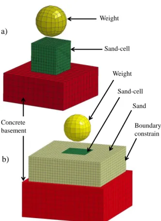
Figure 1. FEM model of the geocell: (a) free deformation (FD) condition, (b) material confinement (MC) condition
Weight
Sand
Boundary constrain Concrete
basement
Sand-cell
a)
b)
Weight Sand-cell
3
Figure 1 illustrates the numerical sand cell model, which included the falling weight, sand, tex- tile bag, and basement. The weight, sand block, and concrete basement were simulated by eight- node elements, while the textile bag was simulated by four-node shell elements.
The “Soil and Crushable Foam with Failure” material model was used to simulate the sand.
This model was first presented by Krieg (1972) based on the Drucker–Prager yield criterion. An elastic linear material model was adopted to model the material behavior of the tank, basement, and weight. The fabric material model, which is a variation of Layered Orthotropic Composite materials and is valid for three- and four-node membrane elements, was employed to describe the mechanical properties of the textile bag.
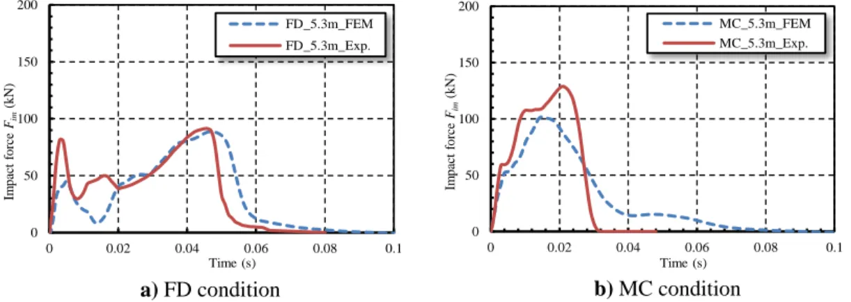
Figure 2. Experimental and analytical impact response results: a) impact force; b) transmitted force
Figure II. Time histories of the impact force
Figure 4. Time histories of the transmitted force
0 150 300 450
0 0.005 0.01 0.015 0.02
Impact force Fim(kN)
Time (s)
50_1.5_FEM 50_1.5_Exp.
a)
0 150 300 450
0 0.005 0.01 0.015 0.02
Transmitted force Ftr(kN)
Time (s)
50_1.5_FEM 50_1.5_Exp.
b)
0 50 100 150 200
0 0.02 0.04 0.06 0.08 0.1
Impact forceFim(kN)
Time (s)
FD_5.3m_FEM FD_5.3m_Exp.
0 50 100 150 200
0 0.02 0.04 0.06 0.08 0.1
Impact forceFim(kN)
Time (s)
MC_5.3m_FEM MC_5.3m_Exp.
a) FD condition b) MC condition
0 50 100 150 200
0 0.02 0.04 0.06 0.08 0.1
Transmitted forceFtr(kN)
Time (s)
FD_5.3m_FEM FD_5.3m_Exp.
0 100 200 300
0 0.02 0.04 0.06 0.08 0.1
Trasmitted forceFtr(kN)
Time (s)
MC_5.3m_FEM MC_5.3m_Exp.
a) FD condition b)MC condition
4
2.3 Model validation
Figures 2-3 compare the numerical and experimental time histories of the impact force, trans- mitted force, and penetration depth from sand tank and sand cell models. Although there was a gap between the experimental and numerical results, the final results of the sand tank impact behavior were in reasonable agreement as shown in Figures
2
. A good match existed between the experi- mental and numerical results of the sand cell models for both FD and MC conditions as shown in Figures3 - 5.
2.4 Effect of drop height on the impact response of a sand cell
The validation of the sand cell numerical model indicated good performance. Therefore, the model was applied further to investigate the impacts from four different drop heights to evaluate the impact phenomenon for different magnitudes of energy. The drop heights H were 3.0, 5.3, 7.5, and 10.0 m. The impact forces, transmitted forces, penetration depths, and impulses are shown in Figures 6-8 to 20. The impact force, transmitted force, and impulse values increased with the drop height and was much greater for the MC condition than for the FD condition. By contrast, penetra- tion depth for FD condition was larger than those for MC condition.
2.5 Conclusion
This paper presented a numerical approach utilizing the FEM code LS-DYNA to model the sand cushion of a protection structure subjected to rockfall impact. The final results obtained by this study can be summarized as follows.
The characteristics of the sand used as a cushioning layer were investigated. The FEM simula- tion (LS-DYNA) using the “MAT_SOIL_AND_FOAM” model could reproduce the impact in the sand tank and on the sand cells with sufficient accuracy for practical use.
Lateral boundary conditions had a significant effect on the results. The transmitted force for the MC condition was adequate to design a protection structure for a rockfall.
This research contributes a better understanding of the influence of sand properties on impact behavior. The success of this research presents new possibilities concerning dynamic analysis by FEM of structures with a sand cushioning layer. The results of this study promote further investiga- tions of impact issues using full-scale rockfall protection walls, galleries, and embankments with sand cells as the cushioning layer.
5
Impact experiment on sand tank over steel H-beams III.
3.1 Introduction
In this sub-study, the series of impact ex- periments on H section steel beam with the sand cushion were conducted with the aim of obtain- ing the fundamental data about the impact action, facilitating designing a protection structure safely and rationally. This thesis reports the knowledge acquired by investigating on the impact force, the absorbing effect of sand cushions, and dynamic interaction between the structure and cushion. Two empirical equations expressing the relationship between oscillation characteristics of the structure and dynamic factor and energy transfer rate were also estab- lished and presented in the paper.
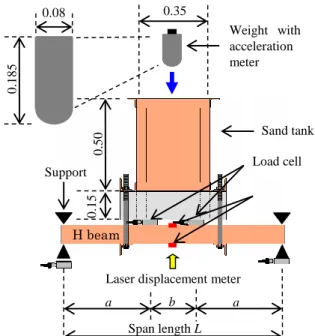
Figure 9 shows the experiment design, in-
volving the sand tank filled up with sand cushion material was fixed to two H-beams with the angle steel beams and bolts in the center of the H-beams, which were simply supported and located in parallel. Loose sand and stone-crushed gravel with small particle sizes were used as two kinds of shock absorbing material.
3.2 Results of experiment
The impact force was calculated by multiplying acceleration by mass of the weight. Equivalent static forces can be determined according to the deflection and the strain resulted from bending moment under this assumption.Figure 10 illustrates time histories of the impact force, transmitted force, and equivalent forces determined by strain and deflection for four cases. Maximum values of forces obtained by impact on gravel, however, were smaller than those values obtained by impact on sand. It becomes clear that the shock absorbing ability of the gravel was more efficient than that of the sand. The length of beam span itself also played an important role in the impact characteris- tics.
Figure 11 presents the results concerning the dynamic multiplication factor related to different falling heights for sand and gravel respectively. The dynamic multiplication factor, ratio of the response of the structure when the maximum dynamic force acts statically and the dynamic re- sponse of the structure is generally expressed in the relationship with Ta/T. Ta/T is the ratio of
Figure 9. Measure devices and dimensions Weight with acceleration meter
Sand tank Load cell
H beam
Laser displacement meter Support
a b a
Span lengthL 0.15 0.50
0.35
0.185
0.08
6
duration of impact force and natural period of structure. There is a logarithmic relationship between Ta/T and the dynamic multiplication factor DMF. Therefore, the equation of the relation between DMF and Ta/T obtained from nonlinear regression analysis was also established as shown in Figure 11.
Figure 10. Impact force, transmitted force and equivalent forces by strain and deflection: a) Sand (L = 1.8 m, H = 2.0 m); b) Sand (L = 3.8 m, H = 2.0 m); c) Gravel (L = 1.8 m, H = 2.0 m); d) Gravel (L =
3.8 m, H = 2.0 m)
Figure 12 shows the relationship between Ta/T and energy transfer rate (ETR) with two kinds of absorbing material. ETR is the proportion (percentage) of transferred energy from the potential energy of the weight to the beam. In this figure, the equation of the relation between Ta/T and ETR is also presented with 0.83 of the correlation index.
3.3 CONCLUSION
In this chapter, series of impact experiments on H-section steel beam with sand cushion were conducted in order to obtain the fundamental data about the impact action. Obtained results in this research are summarized as follows.
- The dynamic behaviors of steel H-beam with cushion under impact were concretely shown including characteristic of the impact force. The concept and actual data concerning the equiva- lent forces were introduced and shown.
- The impact force Pa of the weight colliding on sand cushion was constantly larger than that in the case of gravel cushion.
-12 -8 -4 0 4 8 12
0 0.02 0.04 0.06 0.08 0.1
Pa Pt Ps Pd
Force (kN)
Time (s)
-12 -8 -4 0 4 8 12
0 0.02 0.04 0.06 0.08 0.1
Pa Pt Ps Pd
Force (kN)
Time (s)
-6 -4 -2 0 2 4 6
0 0.02 0.04 0.06 0.08 0.1
Pa Pt Ps Pd
Force (kN)
Time (s)
-6 -4 -2 0 2 4 6
0 0.02 0.04 0.06 0.08 0.1
Pa Pt Ps Pd
Force (kN)
Time (s)
a) b)
c) d)
7
- The transmitted force Pt and two kinds of equivalent force Ps and Pd were evidently affected by the span length L, falling height H and cushion material. Thus, the force in gravel cushion was smaller than that in sand cushion.
Figure 11. Relationship between Ta/T and dynamic multiplication factor DMF
Figure 12. Relationship between Ta/T and of energy transfer rate (ETR)
- Impulse by impact I had quadratic relationship with the falling height of the weight H for both sand and gravel cushion.
- The dynamic multiplication factor DMF had particular relationship with the natural period of the beam T and no relation with the falling height H. The relationship between ETR and the natural period of the beam T also should be considered. Two equations evaluating dynamic multiplica- tion factor DMF and energy transfer rate ETR were established and presented. This achievement offers an application for the similar impact protective structure with sand cushion.
Numerical simulation of impact on rockfall protection IV.
fence
4.1 Introduction
The use of sand–pack to induce the death load acting as landslides was first mentioned in Nishita et al. (2011) with a series of experiments, and some remarkable notices were found in the study. Numerical approach used in this study, which is expected one of the effective method to solve the limitations of the experiments and gain significant insights into mechanical characteristics of structure.
To obtain the achievement, the fence models which were simulated by LS-DYNA explicit fi- nite element method (FEM) code underwent a careful validation. This numerical tool has been successfully used to reproduce the impact behaviors of sand and sand cell subjected to dynamic load of the drop weight by Ho et al., (2013). The validated models were used to investigate the mechanical behaviors of the fence corresponding to the change of the impact energy magnitude.
0 0.4 0.8 1.2 1.6
0 1 2 3 4 5 6
DMF
Ta/T
Sand (Exp.) Gravel (Exp.) sand (Equ.) Gravel (Equ.) DMF= 0.4406aln(Ta/T)+1.205a4.61 Sand: a= 1; Gravel: a= 0.79
0 0.5 1 1.5 2 2.5 3 3.5
0 1 2 3 4 5 6
ETR
Ta/T
Sand (Exp.) Gravel (Exp.) Sand (Equ.) Gravel (Equ.) ETR= -0.9266bln(Ta/T)+0.8879b-0.71 Sand: b= 1; Gravel: b= 0.69
8
The results indicated that sand–pack or landslide mass remarkably influences the mechanical characteristics of the fence bringing both advantages and disadvantages points. For the positive effects, the sand pack could be considered to be used for some practical applications.
In this study, two types of impact experiments on rockfall protection fence, namely the fence excluding sand–pack cushion (FES) and the fence including sand–pack cushion (FIS) were con- ducted. Each type of fence was conducted with two different drop heights of 10 m and 7 m, corresponding to the energy magnitudes of 100 kJ and 70 kJ respectively.
4.2 Numerical model approach
The numerical models in this study were idealized to simulate full-scale protection fences.
Therefore, all components of the fences (e.g., posts, cable nets, border cables, bracing members, diagonal cables and sand–packs and weight) were simulated as the same geometrical dimensions as experimental models of FES_10 and FIS_7 as shown in Figure 13.
Figure 13. Finite element models: a) fence excluding sand–packs (FES_10); b) fence including sand–packs (FIS_7)
4.3 Numerical model validation
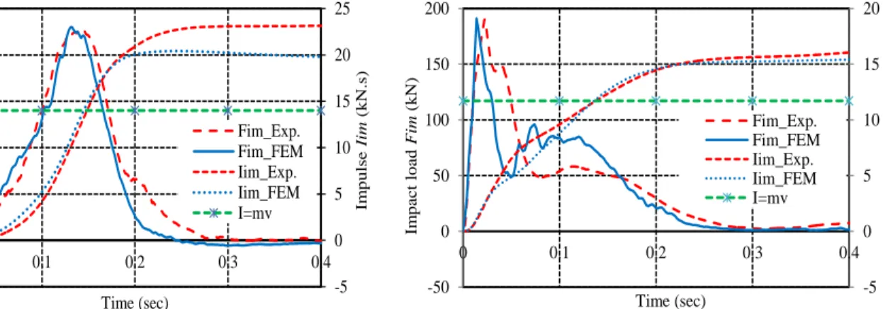
The numerical models according to the description as presented above were validated through the comparison between numerical results and the results obtained from the experiment. The results involve the whole deformation of fence, the time history of displacement of the weight, the time histories of impact force and impulse by the impact force (Figures 14 and 15). Generally, the experimental and numerical results of the displacement response, impact force, impulse by impact, absorbing energy ratio, reaction force, and moment for two models show a good and consistent agreement. This result confirms that the ability of the FEM model has enough ability to reproduce the behavior of full-scale fence with, without sand–pack subjected to impact of drop weight and
a)
b)
9
also provides useful possibility as a tool to investigate further effects of sand–pack on impact phenomenon.
4.4 Application
The numerical models were used to investigate a wide range of energy from 20 kJ to 140 kJ.
According to calculated results, the impulse value from FIS model is clearly smaller than that value from the FES model for the same drop height. The reaction forces obtained from the FIS model are about 15-30% larger than those obtained from the FES model. The transferred energy values within sand–pack component are much higher than those values within other components. The effects of sand tank on cable tensile stresses are also indicated.
The numerical model of FIS_7, then, were used to investigate the effects of position impact on the sand–pack, impact direction and diagonal cable. The results show that the above-investigated conditions have remarkable effect on impact phenomenon.
Figure 14. Impact force and impulse by impact time–
histories from the experimental and numerical result of FES_10 model
Figure 15. Impact force and impulse by impact time–
histories from the experimental and numerical result of FIS_7 model
4.5 Conclusion
In this study, many numerical models of rockfall protection fence with and without sand–packs simulated by FEM have been done successfully. The validated models have been, then, applied for deeper investigation to reach insight into structural response. According to the numerical result analysis and discussion, the content of the study are concluded as follows.
- Generally, sand–packs covered on the fence have strong effects on impact characteristics of rockfall protection fence, such as impact force, impulse by impact, displacement, reaction force and cable stress.
- The arrangement of sand–packs as well as diagonal cables under the net play an important role in dynamic response of the fence.
-5 0 5 10 15 20 25
-50 0 50 100 150 200 250
0 0.1 0.2 0.3 0.4
Impulse Iim(kN.s)
Impact forceFim(kN)
Time (sec)
Fim_Exp.
Fim_FEM Iim_Exp.
Iim_FEM I=mv
-5 0 5 10 15 20
-50 0 50 100 150 200
0 0.1 0.2 0.3 0.4
Impulse Iim(kN・sec)
Impact loadFim(kN)
Time (sec)
Fim_Exp.
Fim_FEM Iim_Exp.
Iim_FEM I=mv
10
- The results of vertical and horizontal impact models are precisely different, however, for safety side consideration, vertical impact test is acceptable choice for experiment.
- Among the above effects of sand–packs, high ability to absorb impact energy and redistribute impact force could be utilized for cushioning layer of the fence.
- The promising results of numerical model using FEM code of LS-DYNA provide a possibility of application of FEM approach for flexible cable fence combining with granular material of sand–packs.
Conclusion
V.
The results achieved from above sub-studies concerning sand cushioning layer are summarized as follows.
- This research is successful to model the impacts on sand tank and sand–cell acting as a compo- nent of rockfall walls or galleries by using FEM code of LS-DYNA. The results of parametric study using this numerical model indicate that geometrical parameters of sand are very im- portant for numerical model of sand. Boundary conditions surrounding sand–cell strongly affect impact characteristics.
- The experimental study on sand tank over steel H-beams indicates that the energy absorbing effective of gravel cushion is higher than that of sand cushion. The relationships between the dynamic multiplication factor (DMF) and energy transfer rate (ETR) and ratio of Ta/T are clearly approximated by exponential functions.
- The results of numerical study on fence with and without sand–packs clearly show the effects of sand–packs on structural impact response. The role of sand–packs in this study is also the same as cushioning layer of rockfall walls and galleries rather than braking devices of the nor- mal flexible fence.
- Arrangement of sand–packs and diagonal cables under the net are also affected to structure response.
- The recent researches on rockfall protection structures have obtained remarkable achievements so far, however, there have been some remained limitations, needed to advance e.g. low impact energy range, small grain size range, short and small size of steel beams as well as single size and shape of the weight. Among these limitations, dynamic behavior of discrete material of sand cushion dealing with above-mentioned characteristics should be revealed more.
Kanazawa, July 2013