Simple Chaotic Oscillator Using Two RC Circuits
Shuhei MASUDA Yumiko UCHITANI Yoshifumi NISHIO (Tokushima University)
1 Introduction
Recently, synchronization phenomena in coupled systems of chaotic oscillators attract many researchers’
attentions as interesting phenomena from a mathe- matic view point of chaos theory. However, a lot of synchronization phenomena of chaos are still veiled and it is necessary to investigate synchronization phe- nomena of various coupled systems.
In this study, simple chaotic circuits using two cou- pled RC circuits are proposed. We observe the gener- ation of interesting chaotic phenomenon.
2 Circuit model
Figure 1 shows the circuit model. In the circuit, two RC circuits are coupled via simple comparators of op- erational amplifiers. The rectangular voltage wave is inputted to the other input terminals of the compara- tors and the comparators produce the output voltage
±E
which is their power supply voltage according to the input signals.
Figure 1: Circuit model.
Figure 2 shows the rectangular voltage wave inputted to the comparators.
Figure 2: Rectangular voltage wave.
By using the following variables and the parameters, v
1= Ex
1, v
2= Ex
2, t = RCτ, (1)
the normalized circuit equations are given as follows.
x
1= k
1e
−τ±1 ,
x
2= k
2e
−τ±1 , (2) where k
1and k
2are the arbitrary constants and
±are decided according to the outputs of the comparators.
3 Computer calculated results
Att: x1-x2 0.4
-0.4
0.4 -0.4
Figure 3: Attractor x
1–x
2x1
x2
τ τ
τ
0
-0.3 0.3
0.3
0
-0.3
0.3
0
-0.3
Vs
Figure 4: Time waveform.
Figures 3 and 4 show computer calculated results for V/E = 0 . 075 and T/RC = 3 . 0. We can confirm that the circuit exhibits chaos.
4 Circuit experimental results
v
1v
2
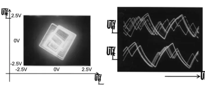
Figure 5: Attractor v
1–v
2.
v
1v
2t
Figure 6: Time waveform.
Figures 5 and 6 show the circuit experimental results for C = 47 μ F and R = 1.2Ω. These results agree well to the computer calculated results.
5 Conclusions
In this study, we have proposed a simple chaotic os- cillator including two RC circuits. We have confirmed that the circuit generated chaotic oscillation by both computer calculations and circuit experiments.
平成20年度電気関係学会四国支部連合大会