先端炭素材の調製と応用 II
1 .炭素ナノ繊維( Carbon nanofiber;CNF) の合成と構造 2 . CNF の応用
九州大学先導物質化学研究所、教授
尹 聖昊
2013年9月27日
炭素資源学特論Ⅳ - 2
Characteristics of CNFs
Unique Properties
Problems
Carbon nanofiber:CNF
Fullerene
CNT
CNF
Zero dimension Basal surface Nano-size
One dimension Basal surface Nano-size
One dimension Various surfaces and structures Nano-size
High price
Very limited application Mass-production
(Frontier Carbon)
Relatively high price
Patent problems
Mass-production
Limited application
Relatively low price
Patent problems
Mass-production
Various applications
Large diameter
Typical classification of CNF Structure
- graphene ((002) layers) alignment to the fiber axis, TEM observation
Various cross sections of CNFs
Polygonal Circle Cross
•However, complicated structure is often found.
•The morphological diversity confirmed simply by SEM observation cannot be neglected, considering possibly their different physical properties.
< Simple cases of CNF structure >
Structural variety of CNFs
Surface of Platelet CNF
Surface of Platelet CNT
Surface of carbon blacks
5 nm
Control of Graphitic Properties of TCNFs
0 5 10 15 20 25 30 35
3.35 3.36 3.37 3.38 3.39 3.4 3.41 3.42 3.43
d
002( Å )
Lc (nm )
MnFe37_CO14 MnFe55_CO14 MnFe73_CO14 MnFe37_CO41 MnFe55_CO41 MnFe73_CO41 Fe_CO14 Fe_CO41 NiFe462_CO14 NiFe462_CO41 NiFe642_CO14 NiFe642_CO41
Control of surface area
20 30 40 50 60 70 80
0 50 100 150 200 250 300 350 400
Surface Area (m2 /g)
Ni Content (wt %)
• CBF fibers 250 ~ 350m2/g, Metal fibers 20 ~ 200 m2/g
• CBF fibers shows 2~10 times higher SA than Metal fibers.
• SEM of CBF fibers with SA around 300 m2/g: small fibrils, fibril aggregate, and rough surface one like activated one.
Metal CBF
50~70 nm
Fibril Aggregate
~150 nm
Rough surface
Some problems of CNFs
1. Patents : Relatively free but some application patents should be considered.
2. Price : ~10~200 $ /kg
- Effective process for mass-production 3. Dimension & Uniformity control
- Diameter
- Surface control; edge / functional groups - Linearity
- Crystallinity, surface area 4. Useful skills : Purification, Dispersion
Objective of this study
Novel Functional Materials of Structure Optimized CNFs
Backgrounds of Objectives :
Functional revolution of CNFs Based on the Carbon Nanotechnology
CNFs
CNF functional composites
CNF catalysts CNF supports
Basic study
Selective preparation
Modification
Composition
Commercialization Applications
Fuel Cell Catalysts
Anodic Materials for LIB Electrode of capacitors
Air Purification
Reduction and Oxidation Catalysts for Green
Chemistry
Refactory 、 FED, Nano-fluid
Synthesis of CNF
CNFs
CNFs related syntheses
Structural Modifications
Selective Preparation of CNFs
Standard CNFs
Target optimized CNFs
CNF functional composites
Mass Production of CNF
Batch process
Pressurized Process CNFs from Waste Gases
Mesoporous CNFs Activation
Electric oxidation PCNF, HCNF, TCNF
Accordion CNF
Small CNF, High SA CNF,
High Graphitic CNF High Dispersable CNF N-doped CNF
CNF-Si, SiO, TiSi CNF-NG、CB
CNF-SiO2, CNF-MgO
Metal & Metal Oxide Nano-chain
Fe3O4, MoO2 nanochain SiO2, SiC nanofibers
Pt, PtRu, Pd, Au nanochain
Electro-spun CNF
Indoor polutions Dilute NOx
De-metal, De-particulation
Preparation (Fixed Bed Method)
exhaust
CO H2 He Mass flow
controller
Catalyst
in the quartz boat
Temperature controller Furnace
Quartz tube
Catalyst : Transition metals, Their alloys or supported catalyst Catalyst preparation method : co-precipitation
1) Best, R. J. and Russell, W. W., J. Amer. Soc. 76, 838(1954)
2) Sinfelt, J. H., Carter, J. L. , and Yates, D. J. C., J. Catal. 24, 283(1972)
Reduction : H
2/He(1/9, 200sccm//4.5 cm diameter tubular furnace, 2h
Reaction : CO/H (4/1 & 1/4v/v%), 200 sccm// 4.5 cm diameter tubular furnace
Bulk Catalyst
Product Furnace
Gas Preparation
of Catalyst
Applications
No ultra-fine particle
CO or C2~C4 HC gas / H2
400 ~ 650 ℃ One step reaction
No purification No further heat treatment
Clean surface Controllable texture Controllable graphitic property Controllable surface area Long or short aspect ratio Controllable diameter High yield
Catalysts for CNF Preparation
• Mono-metal - Fe, Co, Ni
- Fe, Co, Ni / Supports
• Support: Alumina, Silica >>> MgO
• Bimetallic Catalyst
- Fe, Co, Ni / Fe, Ni, Mn, Cu, …/Supports
• Trimetallic Catalyst
- Fe, Co, Ni / Fe, Ni, Cu, Mn / Cr, Al,
…/Supports
Functions of Second or Third Metals ?
Fe
Cr
Cu
Ni Main Catalyst
Fe:Mg=8:2 収率: 1.2倍
Fe:Cr:Mg=6.4:1.6:2 収率 : 4.6倍 繊径 : 40nm
Tubular
Fe:Mn:Mg=6:2:2 収率 : 1.1倍
Fe:Cu:Mg=6:2:2 収率 : 2.0倍
2nd Catalyst
Fe:Cu:Co:Mg=6:1:1:2 収率 : 60.2倍 繊径 : 180nm Herringbone CNF Fe:Cr:Mo:Mg=6:1:1:2
収率 : 27.8倍 繊径 : 20nm
Tubular
Co
Fe:Mn:Co:Mg=4:2:2:2 収率 : 11.6倍
繊径 : 50nm 不均一 CNF
Mn
Co
3rd Catalyst
Co Mo
Fe:Ni:Co:Mg=7:0.5:0.5:2 収率 : 60.2倍
Tri Metallic Catalysts
525 600 675
450
Yie lds
(time s)
Co:Cr:Mg=6:2:2 Co:Mn:Mg=4.8:3.2:2 Co:Al:Mg=6:2:2 Co:Fe:Cr:Mg=4:2:2:2 Co:Ni:Cr:Mg=4:3:1:2 Fe:Cr:Mg=6.4:1.6:2 Fe:Al:Mg=4:4:2
Fe:Ni:Co:Mg=7:0.5:0.5:2 Fe:Cr:Mo:Mg=5.77:1.44:0.8:2
Diame ter of CNF (n
m)
Synthesis Temperature (oC)
750 0
150
75
37.5
112.5
0 60
30
15 45
研究結果
収率, 繊径, 纎維構造などに影響を与えることができる Cr, Mn, Al などの新しい補助触媒の発掘
1. Co 主触媒に対する補助触媒の效果
- Cr 補助触媒は低い合成温度で高い触媒収率を見せ て, 合成温度が低くなるによって Herringbone 構造の 纎維が合成される.
- Mn 及び Al 補助触媒は高い合成温度で高い触媒収 率を見せて, 大部分 Tubular 構造の纎維が合成される.
2. Fe 主株触媒に対する補助触媒の效果
- Cr 及び Al 補助触媒皆合成温度が高いほど触媒収 率が増加する傾向を見せて Tubular 構造の纎維が合 成される.
- Cr 補助触媒の場合には触媒収率が非常に低いが一 方見掛密度が非常に低い纎維が合成される.
- Cr 及び Mo 補助触媒を一緒に使う場合には 30倍以 上の非常に高い触媒収率を得ることができる.
3. FeNiCoMg 触媒
- 最大繊径 120nm 程度の非常に太い Tubular 纎維を 合成する触媒システム.
- Niと Coの含量がそれぞれ 0.5で等しい場合に一番高 い触媒収率及び一番均一な纎維を得ることができる.
0.00
0.25
0.50
0.75
1.00
Diame
ter of C
NF (nm)
Co:Fe:Cr:Mg=4:2:2:2 Co:Ni:Cr:Mg=4:3:2:1 Co:Mn:Mg=4.8:3.2:2 Fe:Al:Mg=4:4:2 Co:Al:Mg=6:2:2 Fe:Ni:Co:Mg=7:0.5:0.5:2 Fe:Ni:Mg=1:4:5 Co:Cr:Mg=6:2:2 Co:Mn:Ni:Mg=3:2:3:2
Bul k Density
Yields (times)
0 15 30 45 60
0 100
50
25 75
研究結果
経済的に有利なC3H8 ガスを利用して C2H4 ガス よ り少し高い温度で CNFを合成
1. 主触媒に対する補助触媒の效果
- Cr 補助触媒は低い合成温度で高い触媒収率を見せ て, Mn 及び Al 補助触媒は高い合成温度で高い触媒収 率を見せる.
- ほとんどすべての触媒組成で Tubular 構造の纎維が 合成される.
2. FeNiCoMg 触媒
- C2H4 ガスを利用して合成した場合とは全然違った素 材が得られる.
- 50nm 程度の纎維も観察されたがほとんど大部分が 纎維形態がカーボン固まり状であり、見掛密度も非常に 高い.
* 모든 CNF의 합성온도는 700℃임.
(Co:Ni:Cr:Mg=4:3:1:2, Fe:Ni:Mg=1:4:5 촉매는 600℃에서 합성한 결과임)
Tri Metallic Catalysts
Sample # SEM TEM Properties Applications Etc.
KNF-SPR Platelet Nano-rod
Platelet high grapht. deg.
80 ~ 400 nm, SA 90 m2/g d002 3.36Å, Lc(002) 30 nm
電池材料, 触媒担 体, 触媒担体
例) 高活性水素化 触媒Ru/PCNF
70 g/日
KNF-SH Herring-
bone
Herringbone high surface area 70 ~ 500 nm, SA 150 m2/g
d002 3.45Å, Lc(002) 3 nm
複合材料, ガス貯 蔵, 吸着剤,触媒担 体, FED
例)DMFC用PtRu触 媒担体
100 g/日
KNF-ST Tubular 高黒鉛化
性
Tubular thin walls, open tips
high grapht.deg.
20 ~ 50 nm, SA 90 m2/g d002 3.37Å, Lc(002) 13 nm
複合材料, 吸着剤,
触媒担体, 触媒 20 g/日
KNF-FM Tubular
小繊径
tubular, hollow 5~15 nm, 4 -7 walls
複合材料、触媒担
体、FED 20 g/日
Standard CNFs
Sample # SEM TEM Properties Applications Product
KNF-CM 小繊径 高分散
Herringbone, hollow 7 ~ 20 nm
複合材料、吸着 剤、
触媒担体、FED
20-30 g/日
KNF-CC 小繊径
Herringbone 7 ~ 15 nm
複合材料、吸着 剤、
触媒担体、FED
15-20 g/日
KNF-NM 中繊径
Herringbone 10~60 nm (30~40)
複合材料、吸着 剤、
触媒担体
50-70 g/日
KNF-NF 中繊径 直線性
Herringbone 20 ~ 50 nm Straightness
複合材料、吸着 剤、
触媒担体
50-70g/日
CNF (Small & Middle Diameters)
Highly graphitic CNFs
CNF of similar graphitic properties with Natural Graphite
CNT usually shows low graphitic properties
Conductive materials or supports for heterogeneous catalysts
PCNF, HCNF
GPCNF
G-PCNF-N
BA-GGPCNF-N GPCNF-N
黒鉛化
硝酸処理
B黒鉛化
p-CNF p-CNF
p-CNF p-CNF
Ref.) S. Lim, et al.. J. Phys. Chem. B108 (5), 1533 – 1536 (2004) p-CNF-G
p-CNF-G p-CNF-G-NAp-CNF-G-NA p-CNF-G-NA-Gp-CNF-G-NA-G
According to the graphitization degree,
we found some difference at edge plane by TEM analysis
Surfaces of PCNF
N-doped CNFs
Ethylene
ml/m (g)
160 160 40 40 0 0 0 Total
200 ml/m
Hydrogen 40 40 40 40 40 40 0
He 0 0 120 120 160 160 200
Acetonitrile (liq.) l/m 0 35 0 35 35 70 35
Input N/C at.% 0 4.6 0 14.5 50 50 50
ET01 ACN01 ET02 ACN02 ACN03 ACN04 ACN05
Reaction Rate (Growth Rate)
C Conv.
N/C atomic ratio of CNF (%)
0 2 4 6 8 10 12
Reaction Rate (g CNF/hr g cat.)
0 5 10 15 20 25
Carbon Conversion Yield (%)
0 10 20 30 40 50 60
N/C
C167N
C54N
C21N
C18N
C10N
N-Source : Acetonitrile
Reaction Temp.
530
oC
N
Preparation of N-doped CNFs
A. Direct Synthesis of Carbon Nanofibers with Nitrogen (the method of this study) B. Deposition of Nitrogen Components on Carbon Nanofibers (Post-synthesis)
• Using Carbon Sources Containing Corresponding Heteroatoms
• Mixing General Carbon Sources with a Nitrogen Source (NH3)
Route A
• One step synthesis
• Graphitic structure
• N both in-plane and at the surface (edge)
Route B
• Two step synthesis
• Amorphous region at the surface (probably unstable)
• N selectively at the surface (edge) Expected features
N N N N N N
Coating
Post-Doping
N N N N N
N N
N N N
N N N
Direct Synthesis
- Synthesis of various fibrous materials based on carbon nano-fibers
Carbon Nano-fiber
•Dispersion of metal precursors on the fiber
•Partial catalytic gasification of carbon with O2, H2, etc.
•KOH activation
Mesoporous CNF
Metal Oxide Nano-fiber (Nano-chain)
Activated CNF (Microporosity)
•Complete catalytic gasification (Removal of carbon)
•Carbon nano-fibers (CNF) can be provided with particular functions by dispersing metal components.
•Furthermore, some reactions between CNF and the metal precursors result in formation of novel
functional materials as described above.
•Removal of catalysts
Fig. 6. TEM images of CNF-1 as prepared (a, e); activated at 850 °C for 1 h (b, f);
activated at 850 °C for 3 h (c, g); and activated at 1000 °C for 1 h (d, h).
Fig. 3. Nitrogen adsorption isotherms (a) and pore size distribution (b) of CNF-1 as
prepared and activated with KOH.
Fig. 4. The d002 (solid circles) and Lc(0 0 2) (open circles) of CNF-1 as prepared and
activated with KOH obtained through X- ray diffraction.
KOH activation of HCNF
Pore wall
Catalytic gasification
Modification of the structure
CH4 or CO2
H2 or O2
catalyst
C*
Pore formation
0.0 0.2 0.4 0.6 0.8 1.0
0 100 200 300 400 500 600 700
0.0 0.2 0.4 0.6 0.8 1.0
0 100 200 300 400 500 600 700
(S=184m2/g)
Volume(cm3 /g)
P/P0
• Herringbone carbon nano-fiber drilled by catalytic gasification
• Herringbone-like pore alignment
• Good pore channeling
• Pore size corresponds to catalyst size
Formation of mesoporous carbon nano-fibers
Ref.) S. Lim, et al., Carbon 45(1):173-9 (2007).
2
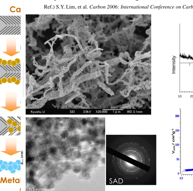
10 20 30 40 50 60 70 80 90
Intensity
Fe3O4, Magnetite (PDF#85-1436)
1.0
p/p0
0.0 0.2 0.4 0.6 0.8 1.0
200
Vads/ cm3g-1
0 50 100 150 200
SAD
XRD
N2-adsorption
Synthesis of Magnetite Nanoparticle-Chain
Ref.) S.Y. Lim, et al. Carbon 2006: International Conference on Carbon, Robert Gordon College, Scotland (2006)
Nano-Chains
Schematic Procedure of SiO2 NF
- Synthesis of SiOx Nano-fibers Using CNF as a template
Carbon Nano-fiber
Metal Oxide Nano-tubes Metal Oxide Nano-fibers
Highly-porous Nano-fibers
or
Coating with Polysilane
Oxidation under Prescribed Conditions
Polycarbomethylsilane (Aldrich)
• average Mw ~800, electronic grade
• mp 79-84 °C
• density 1.1 g/mL at 25 °C(lit.)
• Sol. in Toluene, partly sol. in acetone
• CNF: Herringbone
• 150 nm dia.
• Some coiled
Less fused
Independent Herringbone texture
• Herringbone-like aligned channels
• Several nm-sized width
TEM of SiOx-NF SEM of SiOx-NF
• PS in Toluene * completely soluble
• PS/HCNF 1/5 (w/w)
• 450oC in Air
50 nm
TEM & SEM of SiOx NFs
Various SiOx NFs
TEM of SiOx-NF using PCNF TEM of SiOx-NF using TCNF
PCNF TCNF
Thin CNF Corresponding SiOx-NF
• PS in Acetone
• PS/CNF 1/5 (w/w)
• 450oC in Air
• Thin CNF (~20 nm dia.)
SiOx NF Using Thin CNF
Name of template Synthesis Conditions (in Air 200 ml/min)
Surface Area (m2/g)
Pore Volume (ml/g)
Average Pore Size (nm)
PCNF 700oC-4h 538 2.40 17.8
TCNF 700oC-2h 289 1.10 15.2
NFM 500oC-4h 619 2.58 16.7
Surface Area and Pore Size Distribution depending on the synthesis template
•PS in Toluene
•PS/CNF 1/5 (w/w)
P/P
00.0 0.1 0.2 0.3 0.4 0.5 0.6 0.7 0.8 0.9 1.0 0
200 400 600 800 1000 1200 1400 1600 1800
Adsorption Volume (ml/g)
Pore Width (nm)
dV p
0.1 1 10 100
0.000 0.005 0.010 0.015 0.020 0.025 0.030 0.035
SiOx Nanofibers using PCNF as a template
SA and PSD of SiOx NFs
Layer spacing of platelet SiC:
0.225nm observed under TEM
0.253nm from XRD data according to Bragg equation
Structure model
of platelet nano SiC
β-SiC NF
Nano functional composites
Functional Material
Adsorption Support Electrode
Filler etc.
Improvement of Functions by the composition with CNFs
Function improvement
Function Hybridization
Function Creation
Various CNF composites
Magnifying the functions of basic materials : Silica,Alumina,Si,TiO
2, Magnetites
Silica – CNF Composites
Additive to Tire
Bad compatibility to rubber
CNF-silica composite to solve – Improvement of compatibility
SiO-CNF
Scale up
Vertical type
Scale up
Vertical type Pressure
Horizon type
Capacity : several grams
Capacity : H-, P-CNF 100g/1batch T-CNF 20g/1batch
Capacity: 500g/day
Mass Production of CNFs
Structure of CNF
Old structural models of CNFs
Platelet 炭素ナノ繊維 Herringbone 炭素ナノ繊維 Tubular 炭素ナノ繊維
( Rodriguez, N.M. 1993. J. Mater. Res. 8: 3233 )
Graphitic cones in palladium catalysed carbon nanofibres:分子 → ナノ繊維
Chemical Physics Letters, Volume 343, Issues 3-4, 3 August 2001, Pages 241-250
H. Terrones, T. Hayashi, M. Muñoz-Navia, M. Terrones, Y. A. Kim, N. Grobert, R. Kamalakaran, J.
Dorantes-Dávila, R. Escudero, M. S. Dresselhaus and M. Endo
■カルベール
®とは
カルベールは超微粒子の金属触媒を核 として炭化水素を気相成長させる事によ って得られるカーボンナノチューブです。
http://www.gsi.co.jp/seihin/hightech/carbere.html
Primary Structures of Various CNFs
Assembly of carbon nano-plates Assembly of carbon nano-rods
Platelet CNF Herringbone CNF Tubular CNF Carbon
nano-rod
Carbon nano-plate
Quantitative ratios and Arrangement of primary structures
should determine
Structure, graphitizability, and Most of physical properties of Resultant carbon nanofibers CNF is composed of carbon
Nano-rod and nano-plate。
Fiber axis
Fiber axis 軸方向
Fiber axis
Platelet CNF Herringbone CNF Tubular CNF
As preparedGraphitized
製 作 直 後 黒 鉛 化 後 S T M
Fiber axis 像 Fiber axis
SEM of PCNF, stabilized PCNF and PACNF
100nm
2m
2m
2m
200nm
200nm
200nm PCNF
(starting material)
Stabilized PCNF
PACNF
Assembly of
1.8nm~3.6nm thin film
270oC (0.5oC / min)
600oC in He or
steam activation
Nano particle
assembly structure
Mesoporous CNFs
CNFへのPt-Ru触媒担持
ACF上に成長させたCNF構造 新チャレンジPAN系CNF構造
全体像 拡大像 モデル
Pore Pore
Pore axis
axis
Nano-Rod単 位素 の 選択的ガス化により メゾポーラスが生成さ れる。
CNFの高触媒機能化
(ナノ構造単位を利用した 機能化処理)
新しいチャレンジ
(新CNF構造の発見、新合 成方法の開発)
5%触媒 60%触媒
Pt-Ru触媒
2-10nm
最初にヘキサゴン 面のエッヂ部分や 境界などの欠陥に 析出して、徐々に 全表面を覆う。
モデル
全体像 拡大像 解析 ACFの 表 面 積に 関係なく 主 に 「Nano-
全体像 拡大像 解析
生 成 直 後 は 不 電 導性膜を持つが、
炭素化によって電
Structural Model of TCNF
0.14nm 2.52nm
Cross section model of
primary structural unit (Nano Rod)
Nano-rod assembly Carbon nanofiber Nano-rod
Catalyst
As-prepared CNF
Graphitized CNF
~ 30 nm
~ 20 nm
~ 2.5 nm
~ 2.5 nm
Using oxidation and exfoliation methods to transversely isolate structural unit of PCNFs for further understanding of CNFs' structure.
Separation of structural unit (Nano-platelet)
PCNF Structural unit
Graphene
The relationship between PCNFs and graphene
Introduction
Objective
KMnO4/H2SO4
45
Separation of structural units from GPCNFs
(1)
Through the simple ultrasonic exfoliation, the disc-type structure units and graphene layers are isolated step by step.
(2)
Oxidized structural
units and graphene
discs have graphite
oxide like structure.
Development and control of mesopores in PCNFs
Developing a general method based on the oxidation and heat expansion to
introduce the mesoporous channels
Introduction
Objective
Structural Defects of TCNFs
Heat treatment
As-prepared
Graphitic temp. 2000℃
Graphitic temp. 2800℃
d002(Å) Lc002(nm)
3.369 3.387
3.375
9.5 13.7
16.2
La110(nm)
6.5 6.7
6.9
節
Large scale Small scale
典 型 1
典 型 2
説明
ナノプレットが軸と平行に 並んだ構造
ナノプレットがへリングボ ンCNFのように軸と角度を 持って並んだ構造
KNF-ST
Large scale Small scale 説明
典 型 1
典 型 2
ナノプレットが軸と殆ど平 行に並んだ構造
ナノプレットがへリングボ ンCNFのように軸と角度を 持って並んだ構造
KNF-ST2000
Large scale Small scale 説明
典 型 1
典 型 2
KHF-KH1と類似で、全体
的に非直線状で、ナノロッ ドが軸と平行に並んだ構 造
全体的に直線状で、ナノロ ッドが軸と平行に並んだ構 造
KNF-KH2
Large scale Small scale 説明
典 型 1
ナノチューブのbundleのよ うだが、ナノロッドが軸と平 行に並んだ構造だとも理 解できるかも?
矢印はロッドの繋ぎ部分 だ が 、 正 にNature論 文 で TEMで観察した周期的成 長の痕跡
KNF-JT
Schematic Models of TCNF
Usual CNT
Special TCNF
Novel application?
Applications of CNFs
• Energy saving devices (Battery and Capacitor)
• Nano-fluid
• Supports for heterogeneous catalysts
Fuel Cell, Green Chemistry
• Air cleaning
• Catalyst
• FED, FEBL
• Composites
Carbons in Lithium Ion Batteries
PSI Joint Meeting 2006
Roles of Carbon for Anode of Li-ion Batteries
• Anodic Electrode to Hold Reduced Li-ion Intercalation → Graphite
Surface Electron Transfer into Sealed Void
→ Hard or Low Temperature Calcined Carbon
• Electron Conductive Material
Anodic Carbon and Cathodes Material
• Expansion Moderator
Holding and Release of Ion Is Accompanied with Volumetric Charge
Larger Capacity per Volume → Larger
Expansion
Carbon Electrode for Li-ion Battery
• Graphite electrode is currently established.
Low cost with cheaper natural graphite
Limited capacity less than 372 mAh/g
Limited power density
Larger power density for hybrid vehicle
Glassy carbon with small crystalline unit (Low Cond.) Thinner carbon nanofiber
Larger capacity
Glassy carbon with large inner surface
Si or Sn family (Large volumetric change at Ch/Disc)
Functional nano-composites
Electrode Materials for Lithium Secondary Battery
A spectacularly reactive cathode Nature Materials 2, 705–706 (2003)
Different materials for different applications
Characteristics of Basic Raw Materials
Graphite Si Sn
CNF
Platelet Tubular Herring- bone Capacity
(mAh/g) 350 4000 900 290
(340)
220 (280)
80 (600) Density
(g/cc) 2.24 2.33 5.77~
7.27 2.1 2.1 2.0
Expansion ratio
(time)
1.2 4 3
Less than 1.2
Less than 1.2
Less
than
1.2
0 0.2 0.4 0.6 0.8 1 1.2 1.4 1.6
0 50 100 150 200 250 300 350 400
Discharge Capacity (mAh/g)
Potential (V)
Typical Properties of Synthetic Graphites
Natural Graphite (SPR)
MAG
MGC-graphite - Fine
MGC-graphite - Coarse MGC-graphite - Middle
Natural Graphite (PHF)
0 50 100 150 200 250 300 350 400
0.0 0.2 0.4 0.6 0.8 1.0
P/P0
Va/㎤(STP)/g
p-CNF (67㎡/g) p-CNF-G (43㎡/g) p-CNF-G-NA (54㎡/g) p-CNF-G-NA-G (47㎡/g)
Analysis of physical properties
Isotherm curve
Elemental Analysis
C(%)
Surface area (㎡/g)
Oxidation starting Temp.(℃)
XRD Analysis D002
(Å) Lc002 (㎚)
p-CNF 98.9 67 582 3.363 29
p-CNF-G 99.8 43 680 3.365 59
p-CNF-G-NA 99.6 54 628 3.360 >100
p-CNF-G-NA-G 99.8 47 674 3.362 >100
MAG 99.8 < 4 580 3.354 99
20 40 60 80 100 120
300 400 500 600 700 800 900
Tepperature(℃)
Weight ratio (%)
p-CNF p-CNF-G p-CNF-G-NA p-CNF-G-NA-G MAG 98.9
99.8
99.6
99.8
98.4 98.6 98.8 99.0 99.2 99.4 99.6 99.8 100.0
p-CNF p-CNF-G p-CNF-G-NA p-CNF-G-NA-G
C contents(%)
Elemental analysis TG analysis
XRD analysis
25 26 27 28 29 30 31 32
2theta
p-CNF p-CNF-G p-CNF-G-NA p-CNF-G-NA-G
C(002)
Si(111)
25 26 27 28 29 30 31 32
2theta
p-CNF p-CNF-G p-CNF-G-NA p-CNF-G-NA-G p-CNF
p-CNF-G p-CNF-G-NA p-CNF-G-NA-G
C(002)
Si(111)
XRD analysis
p-CNF p-CNF
Analysis of SEM & TEM Image
p-CNF p-CNF
Ref.) S. Lim, et al.. J. Phys. Chem. B 108 (5), 1533 – 1536 (2004) p-CNF-G
p-CNF-G p-CNF-G-NAp-CNF-G-NA p-CNF-G-NA-Gp-CNF-G-NA-G
According to the graphitization degree,
we found some difference at edge plane by TEM analysis
0.0 0.2 0.4 0.6 0.8 1.0 1.2 1.4 1.6 1.8
0 50 100 150 200 250 300 350
mAh/g
Potential vs. Li/Li+ (V)
1 cy 2 cy 3 cy
p-CNF-G-NA-G
Electrochemical properties
0.0 0.2 0.4 0.6 0.8 1.0 1.2 1.4 1.6 1.8
0 50 100 150 200 250 300 350
mAh/g
Potential vs. Li/Li+ (V)
1 cy2 cy 3 cy
p-CNF
0.0 0.2 0.4 0.6 0.8 1.0 1.2 1.4 1.6 1.8
0 50 100 150 200 250 300 350
mAh/g
Potential vs. Li/Li+ (V)
1 cy 2 cy 3 cy
p-CNF-G
0.0 0.2 0.4 0.6 0.8 1.0 1.2 1.4 1.6 1.8
0 50 100 150 200 250 300 350
mAh/g
Potential vs. Li/Li+ (V)
1 cy 2 cy 3 cy
p-CNF-G-NA
0.0 0.2 0.4 0.6 0.8 1.0 1.2 1.4 1.6 1.8
0 50 100 150 200 250 300 350
mAh/g
Potential vs. Li/Li+ (V)
1 cy 2 cy 3 cy
MAG
Electrochemical properties
• Discharge capacity depends on graphitization degree .
• p-CNF-G-NA ( & -G) showed good electrochemical properties.
• They are almost same with MAG (synthetic graphite)
• But, initial coulombic efficiency is low (52~60%) compared to MAG(over 80%)
0.0 0.3 0.6 0.9 1.2 1.5 1.8
0 50 100 150 200 250 300 350
Discharge capacity (mAh/g)
Potential vs. Li/Li+ (V)
p-CNF p-CNF-G p-CNF-G-NA p-CNF-G-NA-G MAG
0.0 0.3 0.6 0.9 1.2 1.5 1.8
230 250 270 290 310 330
Discharge capacity (mAh/g)
Potential vs. Li/Li+ (V)
p-CNF p-CNF-G p-CNF-G-NA p-CNF-G-NA-G MAG
Discharge capacity (mAh/g) Initial coulombic efficiency(%)
0.25V 0.5V 1.5V
p-CNF 239 270 308 60.4
p-CNF-G 268 290 307 58.2
p-CNF-G-NA 274 308 327 52.5
p-CNF-G-NA-G 285 308 330 59.5
MAG 290 305 320 80.6
In detail
MAG
p-CNF-G-NA p-CNF-G-NA-G p-CNF-G
p-CNF
Effects of Boron Additives – XRD analysis
B/A (5wt%) d002(A) Lc002 (㎚)
p-CNF-G 3.357 > 100
p-CNF-G-NA 3.356 85.4 p-CNF-G-NA-G 3.356 75.4
B/A (20wt%) d002(A) Lc002 (㎚) p-CNF-G 3.357 > 100 p-CNF-G-NA 3.361 > 100 p-CNF-G-NA-G 3.358 > 100
B/C (5wt%) d002(A) Lc002 (㎚) p-CNF-G 3.355 > 100 p-CNF-G-NA 3.359 82.2 p-CNF-G-NA-G 3.357 > 100
B/C (20wt%) d002(A) Lc002 (㎚)
p-CNF-G 3.355 > 100
p-CNF-G-NA 3.355 > 100 p-CNF-G-NA-G 3.355 66.7
Additive - Boric Acid(5wt%)
25 26 27 28 29 30 31
2Theta
p-CNF-G p-CNF-G-NA p-CNF-G-NA-G
Additive - Boron Carbide(5wt%)
25 26 27 28 29 30 31
2Theta
p-CNF-G p-CNF-G-NA p-CNF-G-NA-G
Additive - Boric Acid(20wt%)
25 26 27 28 29 30 31
2Theta
p-CNF-G p-CNF-G-NA p-CNF-G-NA-G
Additive - Boron Carbide(20wt%)
25 26 27 28 29 30 31
2Theta
p-CNF-G p-CNF-G-NA p-CNF-G-NA-G
No additive XRD Analysis D002(Å) Lc002(㎚)
p-CNF 3.363 29
p-CNF-G 3.365 59
p-CNF-G-NA 3.360 >100 p-CNF-G-NA-G 3.362 >100
Compare to no additives,
• Added elements
had an effect on increasing graphitization degree.
• Graphitization degree was increased more by B/C addition.
p-CNF-G (Boric Acid)
40 60 80 100 120
300 400 500 600 700 800 900
Tepperature(℃)
Weight ratio (%)
p-CNF-G p-CNF-G (5% B/A) p-CNF-G (20% B/A)
p-CNF-G-NA (Boric Acid)
40 60 80 100 120
300 400 500 600 700 800 900
Tepperature(℃)
Weight ratio (%)
p-CNF-G-NA p-CNF-G-NA (5% B/A) p-CNF-G-NA (20% B/A)
p-CNF-G-NA-G (Boric Acid)
40 60 80 100 120
300 400 500 600 700 800 900
Tepperature(℃)
Weight ratio (%)
p-CNF-G-NA-G
p-CNF-G-NA-G (5% B/A)
p-CNF-G-NA-G (20% B/A)
Effects of Additive – TG analysis
p-CNF-G (Boron Carbide)
40 60 80 100 120
300 400 500 600 700 800 900
Tepperature(℃)
Weight ratio (%)
p-CNF-G p-CNF-G (5% B/C) p-CNF-G (20% B/C)
p-CNF-G-NA (Boron Carbide)
40 60 80 100 120
300 400 500 600 700 800 900
Tepperature(℃)
Weight ratio (%)
p-CNF-G-NA p-CNF-G-NA (5% B/C) p-CNF-G-NA (20% B/C)
p-CNF-G-NA-G (Boron Carbide)
40 60 80 100 120
300 400 500 600 700 800 900
Tepperature(℃)
Weight ratio (%)
p-CNF-G-NA-G
p-CNF-G-NA-G (5% B/C)
p-CNF-G-NA-G (20% B/C)
Oxidation starting temperature (℃) p-CNF-G p-CNF-G-NA p-CNF-G-NA-G
No additive 680 628 674
B/A ( 5wt%) 686 634 661
B/A (20wt%) 697 670 683
Oxidation starting temperature (℃) p-CNF-G p-CNF-G-NA p-CNF-G-NA-G
No additive 680 628 674
B/C ( 5wt%) 727 671 687
B/C (20wt%) 706 659 700
Effects of Additive – Electrochemical properties
p-CNF-G p-CNF-G-NA p-CNF-G-NA-G
Discharge capacity
(mAh/g) Coulombic
efficiency (%)
Discharge capacity
(mAh/g) Coulombic
efficiency (%)
Discharge capacity
(mAh/g) Coulombic efficiency
0.25V 0.5V 1.5V 0.25V 0.5V 1.5V 0.25V 0.5V 1.5V (%)
No additive 268 290 307 58.2 274 308 327 52.5 285 308 330 59.5
B/A ( 5wt%) 259 294 325 61.1 260 300 334 58.6 276 308 339 58.6
B/A (20wt%) 261 295 325 77.3 266 303 338 70.3 - - - -
B/C ( 5wt%) 233 265 292 66.9 259 303 336 65.7 261 293 323 60.3
B/C (20wt%) 227 268 296 72.7 - - - - 259 300 329 72.2
p-CNF-G
0.0 0.3 0.6 0.9 1.2 1.5 1.8
200 230 260 290 320 350
Discharge capacity (mAh/g)
Potential vs. Li/Li+ (V)
No Additive B/A 5wt%
B/A 20wt%
B/C 5wt%
B/C 20wt%
p-CNF-G-NA
0.0 0.3 0.6 0.9 1.2 1.5 1.8
200 230 260 290 320 350
Discharge capacity (mAh/g)
Potential vs. Li/Li+ (V)
No Additive B/A 5wt%
B/A 20wt%
B/C 5wt%
B/C 20wt%
p-CNF-G-NA-G
0.0 0.3 0.6 0.9 1.2 1.5 1.8
200 230 260 290 320 350
Discharge capacity (mAh/g)
Potential vs. Li/Li+ (V)
No Additive B/A 5wt%
B/A 20wt%
B/C 5wt%
B/C 20wt%
67
Highly graphitic CNFs
CNF of similar graphitic properties with Natural Graphite
CNT usually shows low graphitic properties
Conductive materials or supports for heterogeneous catalysts
PCNF, HCNF
GPCNF
G-PCNF-N
BA-GGPCNF-N GPCNF-N
黒鉛化
硝酸処理
B黒鉛化
6
7
TEM of GPCNF ( B addition )
GPCNF - NA を B 添加後再黒鉛化
GPCNF-NA を
B 添加なしで再黒鉛化
p-CNF p-CNF
PCNF
GPCNF
GPCNFーNA
B添加によって表面が乱れる
STM of GPCNF(B addition)
GPCNF - NA を B 添加後再黒鉛化
GPCNF-NA を
B 添加なしで再黒鉛化 PCNF
GPCNF
GPCNFーNA
B添加によって表面が乱れる
Microscopic observation of PCNFs
PCNF PCNF-G PCNF-G-NA
500 nm
500 nm
500 nm
5 nm 5 nm 5 nm
PCNF-B-G PCNF-B-G-NA
500 nm
500 nm
500nm 500nm
5 nm 5 nm
PCNF PCNF-G
SEI thickness : 3 ~ 5 nm SEI thickness : 15 ~ 25 nm
PCNF
SEI
10nm
Carbon Film
GPCNF
SEI
10nm
Carbon Film
PCNF-B-G
10nm
Carbon Film
PCNF -B-G
SEI
SEI thickness : 2 ~ 5 nm
PCNF-G-NA
SEI thickness : 14 ~ 16 nm
PCNF-B-G-NA
SEI
PCNF -G-NA Carbon
Film
10nm
PCNF -B-G-NA SEI
Carbon Film
5nm SEI thickness : 5 ~ 7 nm