Microstructural damage evolution and arrest in
binary Fe high-Mn alloys with different
deformation temperatures
著者
Motomichi Koyama, Takahiro Kaneko, Takahiro
Sawaguchi, Kaneaki Tsuzaki
journal or
publication title
International Journal of Fracture
volume
213
number
2
page range
193-206
year
2018-08-24
URL
http://hdl.handle.net/10097/00128296
doi: 10.1007/s10704-018-0307-6Microstructural Damage Evolution and Arrest in Binary Fe high-Mn Alloys with Different
Deformation Temperatures
Motomichi Koyama a*, Takahiro Kaneko a, Takahiro Sawaguchi b, and Kaneaki Tsuzaki a
a Department of Mechanical Engineering, Kyushu University, 744 Motooka, Nishi-ku, Fukuoka, Japan 819-0395 b National Institute for Materials Science, 1-2-1 Sengen, Tsukuba, Ibaraki, Japan 305-0047
*Corresponding author: Motomichi Koyama, e-mail. [email protected]
Abstract
We investigated the damage evolution behaviors of binary Fe-28 40Mn alloys (mass%) from 93 to 393 K by tensile testing. The underlying mechanisms of the microstructure-dependent damage evolution behavior were uncovered by damage quantification coupled with in situ strain mapping and post-mortem microstructure characterization. The damage growth behaviors could be classified into three types. In type I, the Fe-28Mn alloy at 93 K showed premature fracture associated with ductile damage initiation and subsequent quasi-cleavage damage growth associated with the -martensitic transformation. In type II, the Fe-28Mn alloy at 293 K and the Fe-32Mn alloy at 93 K showed delayed damage growth but did not stop growing. In type III, when the stacking fault energy was >19 mJ/m2, the damage was strongly arrested until
final ductile failure.
Keywords: high-Mn austenitic steel; -martensite; deformation twinning; damage evolution; digital image correlation; electron channeling contrast imaging
1 2 3 4 5 6 7 8 9 10 11 12 13 14 15 16 17 18 19 20 21 22 23 24 25 26 27 28 29 30 31 32 33 34 35 36 37 38 39 40 41 42 43 44 45 46 47 48 49 50 51 52 53 54 55 56 57 58 59 60
1. Introduction
Fe-High-Mn austenitic alloys have been recognized as high-performance materials because of their transformation-induced plasticity (TRIP) (Grässel et al. 2000; Li et al. 2016), twinning-transformation-induced plasticity (TWIP) (De Cooman et al. 2017; Grässel et al. 2000; Koyama et al. 2013c), non-magnetism with low brittleness at cryogenic temperature (Koyama et al. 2013b; Sasaki et al. 1982), shape memory effect (Koyama et al. 2007; Sato et al. 1982; Wen et al. 2014), low cycle fatigue resistance (Li et al. 2015; Sawaguchi et al. 2015), and low hydrogen embrittlement susceptibility (Koyama et al. 2017; Koyama et al. 2013a; So et al. 2009). Moreover, the high fatigue resistance has been recently clarified to remain even in a hydrogen environment (Tsuzaki et al. 2016). Key factors responsible for these advanced properties are the occurrence of -twinning deformations -martensitic transformation. Therefore, Fe-high-Mn alloys have been expected to have applications as seismic dampers (Sawaguchi et al. 2016) and rail couples (instead of welding) (Sato et al. 2006), as well as in magnetic levitation railway systems (Sasaki et al. 1982) and the hydrogen-related infrastructure (Tsuzaki et al. 2016). To optimize the behavior of the twinning and transformation, thermodynamics-based material design strategies have been developed in terms of the stacking fault energy (SFE) (Curtze et al. 2011; Koyama et al. 2011; Saeed-Akbari et al. 2009). As a result, uniform deformation behavior with various chemical compositions and deformation temperatures is currently predictable (Steinmetz et al. 2013) as long as final fracture occurs after satisfying the Considère criterion.
In contrast, prediction models for the occurrence of premature fracture and local elongation have not been developed in Fe-high-Mn alloys because the underlying mechanisms of micro-damage formation
--martensitic transformation are not well understood. In fact, the micro-damage evolution occurs even in an early stage of plastic deformation, and causes a remarkable degradation of the ductility (Koyama et al. 2012b; Yang et al. 2017). In addition, micro-damage evolution affects even fatigue resistance (Hamada et al. 2009; Ju et al. 2016). Here, note that the micro-damage evolution -martensitic transformation is a plasticity-induced phenomenon, rather than simple brittle cracking, when the deformation-induced microstructure and interfaces are sufficiently ductile (Kaneko et al. 2016; Takaki et al. 1990; Yu et al. 2017). In other words, the damage evolution behavior is significantly dependent on the local plastic strain, which cannot be understood by macroscopic mechanical testing. The "damage" concept has been used to discuss formability and ductile fracture mechanisms in conventional structure materials (Fernandino et al. 2017; Hild et al. 2015). Hence, the elucidation of the microstructural damage evolution behavior is crucial for the development of materials and structural design strategies of Fe-high-Mn alloys.
1 2 3 4 5 6 7 8 9 10 11 12 13 14 15 16 17 18 19 20 21 22 23 24 25 26 27 28 29 30 31 32 33 34 35 36 37 38 39 40 41 42 43 44 45 46 47 48 49 50 51 52 53 54 55 56 57 58 59 60 61
In previous studies, it has been observed that microstructural interactions, such as twin/twin (Müllner et al. 1994a; Müllner et al. 1994b), twin/grain boundary (Koyama et al. 2012a; Rémy) -martensite/twin boundary (Koyama et al. 2012b; Koyama et al. 2012c), and - -martensite (Koyama et al. 2016a; Takaki et al. 1990), result in microscopic stress/strain concentrations, which induce micro-damage incidents in the vicinity of the boundaries. That is, -martensite plates are primary factors affecting the damage evolution behavior. As mentioned above, SFE-based criteria can predict the chemical composition and deformation -martensitic transformation behaviors. Therefore, the basic relationship between deformation-induced microstructure and damage evolution behavior can be clarified by investigating specific microstructures in the vicinity of damage incidents at various deformation temperatures in Fe-Mn binary alloys with different Mn contents. This study aims to obtain a basic understanding of plasticity-driven damage evolution mechanisms
-martensitic transformation by using Fe-Mn binary alloys.
2. Experimental
2.1. Materials and mechanical tests
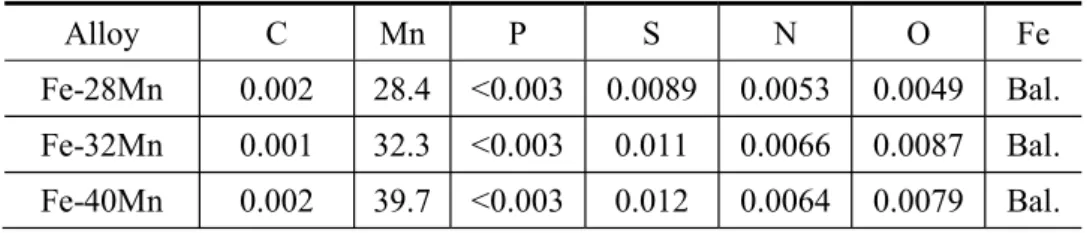
Fe-28Mn, Fe-32Mn, and Fe-40Mn alloys were prepared using vacuum induction melting. 10-kg ingots were forged and rolled at 1273 K; they were then solution treated at 1273 K for 3.6 ks under an argon gas atmosphere and subsequently water quenched. The solution-treated bars were cut by spark machining to obtain the specimen geometries required for the in situ experiments (Fig. 1a) and mechanical testing (Fig. 1b). The chemical compositions of the Fe-Mn alloys are listed in Table 1. The starting temperatures for the s and As)
of the present alloys were estimated by an empirical equation (Lee and Choi). The equilibrium temperature (T0) was
assumed to be (Ms + As)/2. The SFEs were estimated based on (Dumay et al. 2008).
Tensile tests were conducted with an initial strain rate of 10 2 s 1. The deformation temperature was controlled by a
thermostatic chamber to range from 93 to 393 K. The elongation was determined by measuring the gauge length before and after the tensile test using a video extensometer. The tensile tests were carried out twice to confirm reproducibility.
2.2. Quantification of damage evolution behavior
Damage was observed by optical microscopy over a wide observation range. The specimens for optical microscopy 1 2 3 4 5 6 7 8 9 10 11 12 13 14 15 16 17 18 19 20 21 22 23 24 25 26 27 28 29 30 31 32 33 34 35 36 37 38 39 40 41 42 43 44 45 46 47 48 49 50 51 52 53 54 55 56 57 58 59 60
were prepared by mechanical polishing for 1.2 ks with colloidal silica to observe the deformation-induced cracks/voids in the post-mortem specimens used for the tensile testing. The observed part of the specimen is schematically shown in Fig. 1c. The local damage evolution behavior was quantified by measuring the damage area fraction (Da), number of damage
incidents per area (n), and average damage size (dave) for each location in the specimen (Koyama et al. 2014; Tasan et al.
2012). The damage area fraction Da was defined as Da = Ad/Aa, where Aa is the area of the entire region observed, and Ad
is the damaged area. The number of damage incidents per area n was defined as n = N/Aa, where N is the number of damage
incidents for each region. The average damage size dave was defined as dave = Da/n.
The quantitative damage evolution behavior was evaluated by plotting these values against the average reduction in thickness every several hundreds of micrometers from the fractured part. The local thickness (t) used for measuring the reduction in thickness in the post-mortem specimens is shown in Fig. 1d. The obtained reduction in thickness is an alternative parameter to the local plastic strain. The grip part and fractured part of the tensile specimen have 0% strain and maximum plastic strain (reduction in thickness), respectively. An example of damage in an optical micrograph is shown in Fig. 1e. "Damage" in the present study is defined as micro-crack or void that is observable in optical microscopy (Uehata et al. 2018).
2.3. In situ experiments with digital image correlation
In situ deformation experiments with digital image correlation (DIC) were carried out under the optical microscope using the specimens shown in Fig. 1a. The deformation experiments were carried out under a nitrogen atmosphere. For the cryogenic tests at 93 K, the optical microscopic observations were conducted at 293 K to remove the effects of dew condensation. The mechanically polished surfaces of the specimens were etched with a 15% HNO3 + 85% C2H5OH
solution before deformation. The DIC analyses were performed using VIC-2D (Correlated Solutions, Inc.). The step size and subset size for the DIC analyses were set to 2 pixels and 111 × 111 pixels, respectively. Because the DIC analysis is affected by the contrast of the images, the average contrast of the optical micrographs was adjusted.
Fig. 1 Tensile specimen geometries for (a) in situ observations and (b) measurement of stress strain curves. (c) Observation plane for microstructure characterization. (d) Definition of specimen thickness (t) and observation area. (e) Example of microvoids in a fractured Fe-28Mn alloy tested at 293 K.
1 2 3 4 5 6 7 8 9 10 11 12 13 14 15 16 17 18 19 20 21 22 23 24 25 26 27 28 29 30 31 32 33 34 35 36 37 38 39 40 41 42 43 44 45 46 47 48 49 50 51 52 53 54 55 56 57 58 59 60 61
2.4. Microstructure characterization
The specimens for X-ray diffraction (XRD) measurements were chemically polished (H2O2:HF = 20:1) at room
temperature after mechanical polishing. All of the XRD measurements were carried out in the normal direction at 40 kV, 20 mA at a scan speed of 1 /min. All of the scanning electron microscopy-based observations were carried out in post-mortem specimens obtained from the tensile tests. Electron backscattering diffraction (EBSD) analyses were conducted at 15 kV and at a working distance of 18.0 mm. Electron channeling contrast imaging (ECCI) was conducted at 10 kV with a working distance of 3.0 mm.
3. Results and discussion
3.1. Macroscopic tensile behaviors
Figures 2a1 to 2c1 show the engineering stress strain curves of the three alloys at different deformation temperatures.
From these stress strain responses, work hardening rates were obtained, as shown in Figs. 2a2 to 2c2. From the viewpoint
of the Considère criterion, necking occurs when the following equation is satisfied.
/d , (2)
where is the true stress, is the true strain, and d /d is the work hardening rate. That is, the Fe-28Mn alloy showed premature fracture at 93 and 193 K, and the other conditions in the three alloys satisfied Eq. (2) before the final failure occurred. In all of the alloys, the work hardening capability was enhanced by decreasing the temperature and Mn content. The average tensile properties of two tensile tests are summarized in Figs. 2a3 to 2c3. The 0.2% proof stress, 8% flow stress,
and tensile strength tended to decrease with increasing deformation temperature in all of the alloys. These changing trends can be interpreted by conventional considerations associated with thermal activation process of dislocation motion and changes in SFE (Curtze et al. 2011; Koyama et al. 2011; Saeed-Akbari et al. 2009; Steinmetz et al. 2013). On the other hand, the total elongation did not share a common trend against deformation temperature for the three alloys. To understand the Mn content and deformation temperature dependence of the total elongation comprehensively, we need to examine microstructural damage evolution behavior in the Fe-high Mn alloys.
Fig. 2 Deformation temperature dependence of (x1) engineering stress strain response, (x2) work hardening, and (x3) tensile
1 2 3 4 5 6 7 8 9 10 11 12 13 14 15 16 17 18 19 20 21 22 23 24 25 26 27 28 29 30 31 32 33 34 35 36 37 38 39 40 41 42 43 44 45 46 47 48 49 50 51 52 53 54 55 56 57 58 59 60
properties in the (a) Fe-28Mn, (b) Fe-32Mn, and (c) Fe-40Mn alloys. The transformation temperatures were estimated using
Lee's empirical equation (Lee and Choi) -martensite was not observed in the 32Mn and
Fe-40Mn alloys. The As temperature of the Fe- 0.2% 8% B total indicate 0.2% proof
stress, 8% flow stress, tensile strength, and total elongation, respectively.
3.2. Microstructural damage evolution behavior
Figures 3a and 3b show the number density of damage incidents and average damage size plotted against reduction in thickness (damage area fraction is presented in supplementary material: Fig. S1). A significant amount of damage was observed in all of the specimens, even in the undeformed regions (that is, at 0% reduction in thickness), as shown in Fig. 3a. The number of pre-existing damage incidents tended to increase with increasing Mn content. The changing trend in the number of pre-existing damage incidents is caused by the presence of MnS inclusions, whose number density increases with Mn content (the presence of MnS inclusions is indicated in the supplementary material: Fig. S2). The Fe-28Mn alloy
2 (Fig. 3b), and failure occurred at an
early deformation stage without further increase in the number density and size with strain. The Fe-28Mn alloy at 293 K and Fe-32Mn alloy at 93 K showed a sharp increase in average damage size particularly after the size reaches 10-15 2,
which continuously increased with increasing reduction in thickness over 30%. The other conditions did not show a sharp increase in average damage size, and instead, showed either a gradual increase or no increase in damage size. The average damage size remained below 15 2 even with a reduction in thickness of greater than 50%.
Accordingly, the micro-damage evolution behaviors in Fig. 3 are classified into three types, as schematically shown in Fig. 4. Type I is characterized by the occurrence of premature fracture associated with the sudden growth of damage. Type II is characterized by continuous damage growth from an early deformation stage. Type III is characterized by damage arrest. Table 2 shows predominant constituent microstructures, active deformation mechanism, and the classification of the type of damage evolution in the present alloys. Based on the information regarding microstructure and damage evolutions, we explain the detailed characteristics and microstructural mechanisms of the three damage evolution regimes in the following subsections.
Fig. 3 Deformation temperature and Mn content dependencies of (a) number density of damage incidents, and (b) average
1 2 3 4 5 6 7 8 9 10 11 12 13 14 15 16 17 18 19 20 21 22 23 24 25 26 27 28 29 30 31 32 33 34 35 36 37 38 39 40 41 42 43 44 45 46 47 48 49 50 51 52 53 54 55 56 57 58 59 60 61
damage size plotted against the reduction in thickness. The full set of damage evolution data including damage area fraction is presented in supplementary material (Fig. S1).
Fig. 4 Schematic of the classification of damage evolution behavior.
3.2.1 Type I: Burst damage growth
Type I damage growth causes a premature fracture, which occurred in the Fe-28Mn alloy at 93 K, as shown in Fig. 2a2.
To understand the causes of the premature fracture, we examined the correlation between strain localization and micro-damage formation in the Fe-28Mn alloy at 93 K. Island-like strain localization preferentially occurred in locations where
-martensite is present, as shown in Figs. 5(a-c). When the localization of strain associated with -martensite was observed, micro-damage appeared in the strain-localized region (Figs. 5(d, e)). It has been re - -martensite interactions (Takaki et al. 1990) -martensite/grain boundary interactions (Koyama et al. 2012b; Koyama et al. 2012c) result in the formation of micro-damage. Specifically, plastic strain -martensitic transformation in the vicinity of microstructural interfaces, such as grain boundaries. Important characteristics of the damage growth behavior are (i) the damage initiation and growth occur in a relatively early deformation stage (Fig. 3(b)), and (ii) the damage propagates with the sharpness of the damage tip sustained (Fig. 5(e)). The first characteristic originates from the high transformability to -martensite in the Fe-28Mn alloy at 93 K. Since the lower deformation temperature provides a higher driving force for -martensite are given in Fig. S4), the -martensitic transformation rate per strain at 93 K gets higher than 293 K. The higher transformation rate causes the early damage initiation associated with -martensite/interface interactions. In terms of sharp damage propagation, brittle- -martensite at damage tips can be a reason why the damage grew continuously with sustained tip sharpness. Specifically, the damage -martensite fraction increases to approximately 60% with more than 900 MPa remote stress (see Fig. S4), which is associated with the quasi-cleavage cracking at 93 K in the Fe-28Mn alloy. In other words, the damage arrestability is low, and unstable damage growth occurred in an early deformation stage at 93 K in the Fe-28Mn alloy. Therefore, the final damage growth stage cannot be seen in Fig. 3. In addition, note that the stress level at the fractured point in the Fe-28Mn alloy at 93 K is the highest in the present tensile tests. The combined effect of the crack 1 2 3 4 5 6 7 8 9 10 11 12 13 14 15 16 17 18 19 20 21 22 23 24 25 26 27 28 29 30 31 32 33 34 35 36 37 38 39 40 41 42 43 44 45 46 47 48 49 50 51 52 53 54 55 56 57 58 59 60
-martensitic transformation, caused a large stress concentration. Accordingly, premature fracture occurs when the degree of stress concentration at the damage tip provides a critical stress or stress intensity factor for the fracture of the Fe-28Mn alloy.
Fig. 5 Results obtained by in situ deformation experiments at 93 K in the Fe-28Mn alloy. (a) Optical micrographs of the undeformed microstructure. The line diagrams indicate the procedure for the observation and subsequent deformation processes.
Strain contour maps at cross- ave indicates the average strain in the region used
for the strain mapping. (d) A magnified strain maps of the region highlighted in (c). (e) A secondary electron (SE) image of the fractured specimens at a location corresponding to (d). The dashed lines in (d) and (e) indicate the identical region where the micro-damage formed. The full sets of strain mapping results with different deformation temperatures are given in Fig. S6.
3.2.2 Type II: Continuous damage growth
In type II damage growth, the damage growth is once arrested by damage blunting but reinitiates propagation with a stable crack growth regime associated with plastic strain evolution. This type of damage growth was observed in the Fe-28Mn alloy at 293 K and the Fe-32Mn alloy at 93 K. The damage initiation behavior is similar to type I, which is associated with strain localization, as shown in Fig. 6 (case of the Fe-32Mn alloy at 93 K is given in Fig. S7). Correspondingly, a local contrast change to white in the ECC image was observed in Fig. 7(a). The contrast change is attributed to dislocation multi -martensite plate, which caused formation of
micro-- -martensite (Figs.
7(b)). Note here -martensite per strain and (2) remote stress (flow stress) under type II damage growth conditions are lower than that in type I damage growth condition. Because of these two factors, quasi-cleavage cracking does not occur. Instead, the type II micro-damage grows through the repeated microvoid formation and subsequent coalescence, as shown in Fig. 7(c), which is an important difference between types I and II. In the type II damage growth process, the damage tip is blunted, as shown in Figs. 8(d) and (e). However, type II damage growth does not stop, although the damage growth rate is lower than that of type I. In the Fe-28Mn alloy at 293 K, a high damage initiation probability and its damage growth/coalescence cause a decrease in the macroscopic work hardening rate, which accelerates to satisfy the Considère criterion. In contrast, the Fe-32Mn alloy at 93 K showed remarkably higher work 1 2 3 4 5 6 7 8 9 10 11 12 13 14 15 16 17 18 19 20 21 22 23 24 25 26 27 28 29 30 31 32 33 34 35 36 37 38 39 40 41 42 43 44 45 46 47 48 49 50 51 52 53 54 55 56 57 58 59 60 61
hardening rates than the Fe-28Mn alloy at 293 K (Fig. 2b2), which results in a superior strength-elongation balance (Fig.
2b1). An important microstructural characteristic of the Fe32Mn alloy at 93 K is the simultaneous occurrence of
-martensitic transformation and -twinning, as shown in Figs. 8(a) and (b) -twinning plays a similar role in damage initiation (Fig. 8(b)), the probability of the damage initiation -
-- -martensite), the region - -martensite, reducing the probability of damage initiation, as demonstrated in Fig. 3(a). This fact reduced the probability of damage coalescence, resulting in high tensile deformability. In addition, note that the work hardening rates of the Fe-32Mn alloy at 93 K are higher than the Fe-28Mn alloy at 293 K, even at an early -martensite fraction is lower. This is because of the TWIP effect instead of the TRIP effect. Consequently, the Fe-32Mn alloy at 93 K simultaneously realized sustained work hardening capability, low damage initiation probability, and delayed damage growth.
Fig. 6 Results obtained by in situ deformation experiments at 293 93 K in the Fe-28Mn alloy. (a) Optical micrographs of the undeformed microstructure. Strain contour maps at cross- ave indicates
the average strain in the region used for the strain mapping. (d) A Magnified strain map of the region highlighted in (c). (e) A SE image of the fractured specimens at a location corresponding to (d). The arrows in (d) and (e) indicate identical points where micro-damage formed.
Fig. 7 A set of micrographs of the Fe-28Mn alloy deformed at 293 K. ECC images at (a) 5% and (b) 20% reduction in thickness. (c) Magnified ECC image corresponding to the region indicated by dashed lines in (b). In (a), the surface orientation of the right grain is optimized for the Bragg condition, therefore, the right austenite grain appears black, meaning there is little back-scatter electron strength. The black arrows indicate microvoids. (d) Phase and (e) rolling direction (RD)-inverse pole figure (IPF) maps at 30% reduction in thickness at a beam step size of 60 nm.
Fig. 8 Phase and RD-IPF maps overlapped with image quality images of the Fe-32Mn alloy deformed at 93 K taken at reduction in thicknesses of (a) 27% and (b) 28%. The beam step size was 60 nm.
1 2 3 4 5 6 7 8 9 10 11 12 13 14 15 16 17 18 19 20 21 22 23 24 25 26 27 28 29 30 31 32 33 34 35 36 37 38 39 40 41 42 43 44 45 46 47 48 49 50 51 52 53 54 55 56 57 58 59 60
3.2.3 Type III: Damage arrest
Type III damage growth causes full ductile fracture after satisfying Considère's criterion, where the major damage initiation sites are the MnS inclusions (e.g., Fig. 9(a)). This damage growth type was observed when the SFE was higher than about 19 mJ/m2. Most damage was clearly arrested until over 50% reduction in thickness, as shown in Fig. 9(c).
-martensite-related microstructural heterogeneity reduces the damage initiation probability. Even when damage is initiated at grain and twin boundaries, the damage remains small because of the blunting of the damage tip (Fig. 10) in the type III conditions. This is because the work hardening rates are lower than those for types I and II, which enables the damage tip to be blunted with a lower stress increase under a lower remote stress. Because
-martensite and the ease of blunting the damage tip, the damage growth is completely arrested.
Since the multiple mechanical and microstructural factors co-act, the damage evolution behavior cannot be predicted by a single parameter. However, the increase in the SFE positively affects most of the factors that increase the damage initiation resistance and arrestability. More specifically, the damage initiation probability of the binary Fe high-Mn alloys
can be minimized -martensite (and
partly deformation twin), (2) decreasing remote stress (flow stress), and (3) decreasing number density of inclusion such as MnS. The increase in the SFE contributes to the first and second factors. The damage arrestability can be maximized by -martensite fraction at a damage tip, (2) decreasing remote stress, and (3) decrease work hardening capability that enables damage tip blunting. The increase in the SFE positively affects all of the three factors for damage arrestability. Hence, the SFE criterion is expected to be used as the most comprehensive parameter for predicting damage initiation resistance and arrestability of the Fe-high-Mn binary alloys. However, as seen in Fig. 2, the increase in work hardening capability by increasing SFE deteriorates uniform elongation. That is, in terms of the SFE effects, macroscopic necking resistance and microstructural damage resistance are trade-off, which complicates the compositional and temperature dependence of total elongation.
In this context, it is noteworthy that a co-effect of -twinning and reverse transformation can accommodate the problem of the strain -martensite, as shown in Fig. 11. Because the deformation temperature (393 K) is higher than the T0, deformation- -martensitic transformation cannot occur at 393 K in the Fe-28 Mn
alloy. In an early deformation stage -martensite was observed (Fig. 11a). According to an orientation analysis with -martensite plates have different crystallographic 1 2 3 4 5 6 7 8 9 10 11 12 13 14 15 16 17 18 19 20 21 22 23 24 25 26 27 28 29 30 31 32 33 34 35 36 37 38 39 40 41 42 43 44 45 46 47 48 49 50 51 52 53 54 55 56 57 58 59 60 61
orientations that correspond to {10- -twins, which has been reported in other high Mn austenitic steels (Zhang and Sawaguchi 2018; Zhang et al. 2011a; Zhang et al. 2011b) -twinning accommodates the plastic anisotropy of the hcp structure, suppressing the damage formation in the early deformation stage. -martensite reversely transformed (Fig. 11d), and instead, deformation -twinning occurred (Fig. 11e). In this condition, micro-damages are blunted, and elongated well in the late deformation stage, as shown in Fig. 11f. That is, the Fe-28Mn alloy at 393 K showed type III damage growth, even though a considerable amount of pre- -martensite was present.
Fig. 9 Phase and RD-IPF maps of the Fe-32Mn alloy deformed at 293 K taken at a reduction in thickness of (a, a') 20%, (b, b') 40%, and (c, c') 52%. The beam step sizes were 200, 60, and 60 nm, respectively. The phase maps are overlaid with image quality maps.
Fig. 10 (a) SE image of the Fe-40Mn alloy deformed at 93 K taken at a reduction in thickness of 45%. (b, c) Magnified images of the region indicated by dashed lines in (a). The arrows indicate damage incidents (b) at a vicinity of grain boundary and (c) along deformation-induced plates. The elongated damage associated with MnS particles are also clearly seen in (b, c).
Fig. 11 Sets of microstructural images of the Fe-28Mn alloy deformed at 393 K. (a) Phase and (b) rolling direction (// tensile axis) RD-IPF maps with a beam stem size of 200 nm at a reduction in thickness of 5%. (c) High-resolution RD-IPF map at a beam step size of 60 nm, which corresponds to the region indicated by dotted lines in (b). The yellow arrows indicate {10- -twins. (d) Phase and (e) RD-IPF maps with a beam step size of 200 nm at a reduction in thickness of 20%. (f) SE image showing microvoids at a vicinity of the fractured part (>50% reduction in thickness).
5. Conclusions
In this study, the microstructural damage evolution mechanisms of Fe-high-Mn binary alloys were investigated at different test temperatures. As a consequence, the damage tolerance of the binary Fe high-Mn alloys predominantly depends on (1) -martensitic transformability, (2) work hardening capability, and (3) inclusion density such as MnS.
-martensite causes plastic strain inhomogeneity, causing plasticity-driven micro-damage evolution at microstructural interfaces. The work hardening capability -martensite transformability, controls 1 2 3 4 5 6 7 8 9 10 11 12 13 14 15 16 17 18 19 20 21 22 23 24 25 26 27 28 29 30 31 32 33 34 35 36 37 38 39 40 41 42 43 44 45 46 47 48 49 50 51 52 53 54 55 56 57 58 59 60
remote stress (flow stress) and local st -martensite, high remote and local stresses, and high density of inclusion cause micro-damage formation at a damage tip or brittle-like crack propagation. However, even when the damage number density increases, it does not act as a critical factor for failure because of the damage arresting phenomenon. The ability to arrest damage depends on the remote stress, stress concentration at damage tips, and damage tip blunting behavior. The damage arrestability can be significant at a SFE of >19 mJ/m2 in the binary
alloys. In an extreme case that the damage arrestability is lacked, a premature fracture occurs, which critically deteriorates tensile ductility of the Fe-high-Mn alloys.
Acknowledgements
This work was financially supported by JSPS KAKENHI (JP17H04956).
References
Curtze S, Kuokkala VT, Oikari A, Talonen J, Hänninen H (2011) Thermodynamic modeling of the stacking fault energy of austenitic steels Acta Materialia 59:1068-1076 doi:10.1016/j.actamat.2010.10.037
De Cooman BC, Estrin Y, Kim SK (2017) Twinning-induced plasticity (TWIP) steels Acta Materialia doi:10.1016/j.actamat.2017.06.046
Dumay A, Chateau JP, Allain S, Migot S, Bouaziz O (2008) Influence of addition elements on the stacking-fault energy and mechanical properties of an austenitic Fe Mn C steel Materials Science and Engineering: A 483:184-187 doi:10.1016/j.msea.2006.12.170
Fernandino DO, Cisilino AP, Toro S, Sanchez PJ (2017) Multi-scale analysis of the early damage mechanics of ferritized ductile iron International Journal of Fracture 207:1-26 doi: 10.1007/s10704-017-0215-1
Grässel O, Krüger L, Frommeyer G, Meyer LW (2000) High strength Fe Mn (Al, Si) TRIP/TWIP steels development properties application International Journal of Plasticity 16:1391-1409 doi:10.1016/S0749-6419(00)00015-2 Hamada AS, Karjalainen LP, Puustinen J (2009) Fatigue behavior of high-Mn TWIP steels Materials Science and Engineering:
A 517:68-77 doi:10.1016/j.msea.2009.03.039
Hild F, Bouterf A, Roux S (2015) Damage measurements via DIC International Journal of Fracture 191:77-105 doi: 10.1007/s10704-015-0004-7
Ju Y-B, Koyama M, Sawaguchi T, Tsuzaki K, Noguchi H (2016) In situ microscopic observations of low-cycle fatigue-crack propagation in high-Mn austenitic alloys with deformation- -martensitic transformation Acta Materialia 112:326-336 doi:10.1016/j.actamat.2016.04.042
Kaneko T, Koyama M, Fujisawa T, Tsuzaki K (2016) Combined Multi-scale Analyses on Strain/Damage/Microstructure in Steel: -martensitic Transformation ISIJ International 56:2037-2046 doi: 10.2355/isijinternational.ISIJINT-2016-272
Koyama M, Akiyama E, Lee Y-K, Raabe D, Tsuzaki K (2017) Overview of hydrogen embrittlement in high-Mn steels International Journal of Hydrogen Energy 42:12706-12723 doi:10.1016/j.ijhydene.2017.02.214
1 2 3 4 5 6 7 8 9 10 11 12 13 14 15 16 17 18 19 20 21 22 23 24 25 26 27 28 29 30 31 32 33 34 35 36 37 38 39 40 41 42 43 44 45 46 47 48 49 50 51 52 53 54 55 56 57 58 59 60 61
Koyama M, Akiyama E, Sawaguchi T, Raabe D, Tsuzaki K (2012) Hydrogen-induced cracking at grain and twin boundaries in an Fe Mn C austenitic steel Scripta Materialia 66:459-462 doi:10.1016/j.scriptamat.2011.12.015
Koyama M, Akiyama E, Tsuzaki K, Raabe D (2013) Hydrogen-assisted failure in a twinning-induced plasticity steel studied under in situ hydrogen charging by electron channeling contrast imaging Acta Materialia 61:4607-4618 doi:10.1016/j.actamat.2013.04.030
Koyama M, Lee T, Lee CS, Tsuzaki K (2013) Grain refinement effect on cryogenic tensile ductility in a Fe Mn C twinning-induced plasticity steel Materials & Design 49:234-241 doi:10.1016/j.matdes.2013.01.061
Koyama M, Murakami M, Ogawa K, Kikuchi T, Sawaguchi T (2007) Influence of Al on shape memory effect and twinning
induced plasticity of Fe-Mn-Si-Al system alloy Materials transactions 48:2729-2734
doi:10.2320/matertrans.MRA2007124
Koyama M, Okazaki S, Sawaguchi T, Tsuzaki K (2016) Hydrogen embrittlement susceptibility of Fe-Mn binary alloys with high -martensite, and Mn concentration Metallurgical and Materials Transactions A 47:2656-2673 doi:10.1007/s11661-016-3431-9
Koyama M, Sawaguchi T, Lee T, Lee CS, Tsuzaki K (2011) Work hardening associated with -martensitic transformation, deformation twinning and dynamic strain aging in Fe 17Mn 0.6 C and Fe 17Mn 0.8 C TWIP steels Materials Science and Engineering: A 528:7310-7316 doi: 10.1016/j.msea.2011.06.011
Koyama M, Sawaguchi T, Tsuzaki K (2012) Premature Fracture Mechanism in an Fe-Mn-C Austenitic Steel Metallurgical and Materials Transactions A 43:4063-4074 doi: 10.1007/s11661-012-1220-7
Koyama M, Sawaguchi T, Tsuzaki K (2012) Quasi-cleavage Fracture along Annealing Twin Boundaries in a Fe-Mn-C Austenitic Steel ISIJ International 52:161-163 doi: 10.2355/isijinternational.52.161
Koyama M, Sawaguchi T, Tsuzaki K (2013) TWIP effect and plastic instability condition in an Fe Mn C austenitic steel ISIJ International 53:323-329 doi: 10.2355/isijinternational.53.323
Koyama M, Tasan CC, Akiyama E, Tsuzaki K, Raabe D (2014) Hydrogen-assisted decohesion and localized plasticity in dual-phase steel Acta Materialia 70:174-187 doi: 10.1016/j.actamat.2014.01.048
Lee Y-K, Choi C (2000) -Mn binary system
Metallurgical and Materials Transactions A 31:355-360 doi:10.1007/s11661-000-0271-3
Li H, Koyama M, Sawaguchi T, Tsuzaki K, Noguchi H (2015) Importance of crack-propagation- -martensite in strain-controlled low-cycle fatigue of high-Mn austenitic steel Philosophical Magazine Letters:1-9
Li Z, Pradeep KG, Deng Y, Raabe D, Tasan CC (2016) Metastable high-entropy dual-phase alloys overcome the strength-ductility trade-off Nature 534:227-230 doi:10.1038/nature17981
Müllner P, Solenthaler C, Speidel MO (1994) Second order twinning in austenitic steel Acta Metallurgica et Materialia 42:1727-1732 doi:10.1016/0956-7151(94)90382-4
Müllner P, Solenthaler C, Uggowitzer PJ, Speidel MO (1994) Brittle fracture in austenitic steel Acta Metallurgica et Materialia 42:2211-2217 doi:10.1016/0956-7151(94)90300-X
Rémy L (1981) The interaction between slip and twinning systems and the influence of twinning on the mechanical behavior of fcc metals and alloys Metallurgical Transactions A 12:387-408 doi:10.1007/bf02648536
Saeed-Akbari A, Imlau J, Prahl U, Bleck W (2009) Derivation and Variation in Composition-Dependent Stacking Fault Energy Maps Based on Subregular Solution Model in High-Manganese Steels Metallurgical and Materials Transactions A 40:3076-3090 doi:10.1007/s11661-009-0050-8 1 2 3 4 5 6 7 8 9 10 11 12 13 14 15 16 17 18 19 20 21 22 23 24 25 26 27 28 29 30 31 32 33 34 35 36 37 38 39 40 41 42 43 44 45 46 47 48 49 50 51 52 53 54 55 56 57 58 59 60
magnetic Steel and Its Application to Various Products for Commercial Use Transactions of the Iron and Steel Institute of Japan 22:1010-1020 doi:10.2355/isijinternational1966.22.1010
Sato A, Chishima E, Soma transformation in Fe-30Mn-1Si alloy single crystals
Acta Metallurgica 30:1177-1183 doi:10.1016/0001-6160(82)90011-6
Sato A, Kubo H, Maruyama T (2006) Mechanical Properties of Fe-Mn-Si Based SMA and the Application Materials Transactions 47:571-579 doi:10.2320/matertrans.47.571
Sawaguchi T, Maruyama T, Otsuka H, Kushibe A, Inoue Y, Tsuzaki K (2016) Design Concept and Applications of Fe-Mn-Si-Based Alloys -from Shape-Memory to Seismic Response Control Materials Transactions 57:283-293 doi:10.2320/matertrans.MB201510
Sawaguchi T et al. (2015) Designing Fe Mn Si alloys with improved low-cycle fatigue lives Scripta Materialia 99:49-52 doi:10.1016/j.scriptamat.2014.11.024
So KH, Kim JS, Chun YS, Park K-T, Lee Y-K, Lee CS (2009) Hydrogen Delayed Fracture Properties and Internal Hydrogen Behavior of a Fe-18Mn-1.5Al-0.6C TWIP Steel ISIJ International 49:1952-1959 doi:10.2355/isijinternational.49.1952 Steinmetz DR et al. (2013) Revealing the strain-hardening behavior of twinning-induced plasticity steels: Theory, simulations,
experiments Acta Materialia 61:494-510 doi:10.1016/j.actamat.2012.09.064
Takaki S, Furuya T, Tokunaga Y (1990) Effect of Si and Al Additions on the Low Temperature Toughness and Fracture Mode of Fe-27Mn Alloys ISIJ International 30:632-638 doi:10.2355/isijinternational.30.632
Tasan CC, Hoefnagels JPM, Geers MGD (2012) Identification of the continuum damage parameter: An experimental challenge in modeling damage evolution Acta Materialia 60:3581-3589 doi:10.1016/j.actamat.2012.03.017
Tsuzaki K, Fukuda K, Koyama M, Matsunaga H (2016) Hexagonal close-packed Martensite-related Fatigue Crack Growth under the Influence of Hydrogen: Example of Fe 15Mn 10Cr 8Ni 4Si Austenitic Alloy Scripta Materialia 113:6-9 doi:10.1016/j.scriptamat.2015.10.016
Uehata N, Koyama M, Takagi S, Tsuzaki K (2018) Optical Microscopy-Based Damage Quantification: an Example of Cryogenic Deformation of a Dual-Phase Steel ISIJ International In press
Wen YH, Peng HB, Raabe D, Gutierrez-Urrutia I, Chen J, Du YY (2014) Large recovery strain in Fe-Mn-Si-based shape memory steels obtained by engineering annealing twin boundaries Nature Communications 5:4964 doi:10.1038/ncomms5964 Yang CL, Zhang ZJ, Zhang P, Zhang ZF (2017) The premature necking of twinning-induced plasticity steels Acta Materialia
136:1-10 doi:10.1016/j.actamat.2017.06.042
Yu H-Y et al. (2017) Post-uniform elongation and tensile fracture mechanisms of Fe-18Mn-0.6C-xAl twinning-induced plasticity steels Acta Materialia 131:435-444 doi:10.1016/j.actamat.2017.04.011
Zhang X, Sawaguchi T (2018) Twinning of deformation- -martensite in Fe-30Mn-6Si shape memory alloy Acta Materialia 143:237-247 doi:https://doi.org/10.1016/j.actamat.2017.10.009
Zhang X, Sawaguchi T, Ogawa K, Yin F, Zhao X (2011) Orientation dependence of variant selection and intersection reactions of martensite in a high-manganese austenitic steel Philosophical Magazine Letters 91:563-571 doi:10.1080/09500839.2011.596492
Zhang X, Sawaguchi T, Ogawa K, Yin F, Zhao X (2011) A structure created by intersecting martensite variant plates in a high-manganese steel Philosophical Magazine 91:4410-4426 doi:10.1080/14786435.2011.608734
1 2 3 4 5 6 7 8 9 10 11 12 13 14 15 16 17 18 19 20 21 22 23 24 25 26 27 28 29 30 31 32 33 34 35 36 37 38 39 40 41 42 43 44 45 46 47 48 49 50 51 52 53 54 55 56 57 58 59 60 61
Table 2 Initial microstructures and deformation mechanisms. Dislocation slip deformation occurs in all alloys at all deformation temperatures. The XRD profiles and microstructural images used for these identifications are provided
in supplementary materials: Figs. S3-5. Initial
microstructure
Deformation mechanism Damage
growth type
Fe-28Mn, 393 K Austenite +
-martensite
reverse transformation Type III
Fe-28Mn, 293 K -martensitic transformation Type II
Fe-28Mn, 93 K Type I
Fe-32Mn, 393 K
Austenite
-twinning Type III
Fe-32Mn, 293 K -martensitic transformation
-twinning
Fe-32Mn, 93 K Type II
Fe-40Mn, 293 K Only dislocation slip deformation Type III
Fe-40Mn, 93 K -twinning
Alloy C Mn P S N O Fe
Fe-28Mn 0.002 28.4 <0.003 0.0089 0.0053 0.0049 Bal.
Fe-32Mn 0.001 32.3 <0.003 0.011 0.0066 0.0087 Bal.
S.1. Full set of quantified microstructural damage evolution behaviors
Fig. S1 Deformation temperature and Mn content dependencies of (a) the damage area fraction, (b) number density of damage incidents, and (c) average damage size plotted against the reduction in thickness.
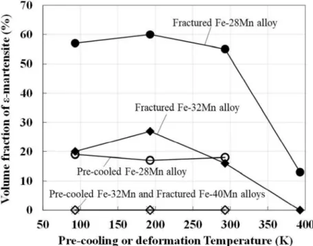
Figures S3 shows XRD profiles obtained before and after the deformation until fracture. The volume fraction of -martensite at each condition was obtained from the XRD profiles as summarized in Fig. S4. Only the Fe-28Mn -martensite, and the initial microstructures of the other alloys are fully austenitic. -martensite did not change significantly, even after cooling. Deformation-induced -martensitic transformations were detected below 293 K in the Fe-28Mn and Fe-32Mn alloys. No significant quantity of -twins was observed at these temperatures. That is, an active deformation mode at 293 and 93 K in the Fe-28Mn alloy is deformation- -martensitic transformation. -martensite rather decreased by deformation at 393 K in the Fe-28Mn alloy, which indicates
deformation-transformation. -twins at 393 K, as shown in Fig. 11e. These results indicate that the active deformation mode in the Fe-28Mn alloy at 393 K is a deformation-induced -twinning. In addition, the amount of deformation- -martensite of the fractured specimens decreased with increasing Mn content but was not significantly dependent on the deformation temperature.
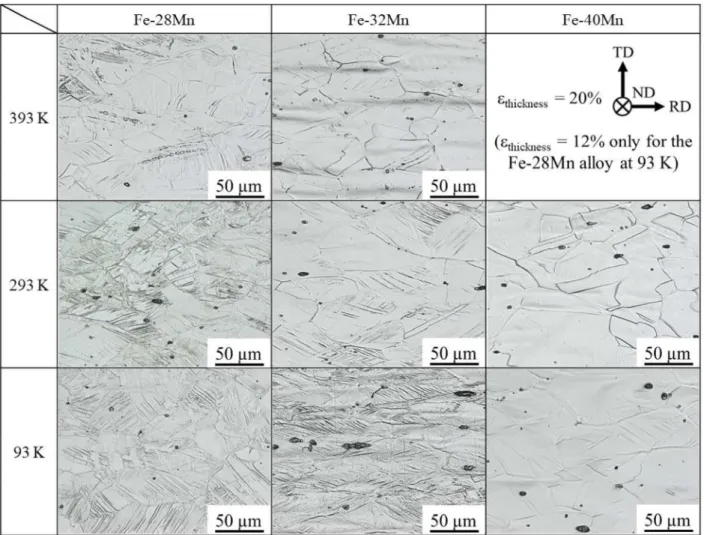
Figure S5 shows optical micrographs at 20% reduction in thickness in the fractured specimen (the image of the Fe-28Mn alloy deformed at 93 K is taken at 12% reduction in thickness because of the premature fracture). The number of plates increased with decreasing deformation temperature and Mn content. In the Fe-32Mn alloy, deformation-induced plates were even observed at 393 K, which is nearly the As temperature (Fig. S5). Because
- -twins can emerge on the etched specimen surface in this alloy, the plates induced around the As -twins. In addition, some of the deformation plates
at 293 K and 93 K in the Fe-32Mn alloy -twins, as indicated in Figs. 8b and 9. -twinning occurred at all deformation temperatures in the present study. Simultaneously, the deformation- -martensitic transformation was active at 293 and 93 K because a signific -martensite was measured only after deformation (Fig. S4).
No -martensite appeared in the Fe-40Mn alloy, irrespective of deformation temperature, as shown in Fig. S4. As observed in Fig. S5, deformation-induced plates were observed only at 93 K. These results suggest that only -twinning was activated by decreasing temperature to 93 K.
Fig. S3 XRD profiles before deformation (x1) and after fracture (x2) in the (a) Fe-28Mn, (b) Fe-32Mn, and (c)
Fe-40Mn alloys.
Fig. S5 Deformation temperature and Mn content dependencies of the microstructure at 20% reduction in thickness. The reduction in thickness for the image obtained at 93 K in the Fe-28Mn alloy is 12%, which corresponds to the fracture strain.
S3. Full set of strain mapping results
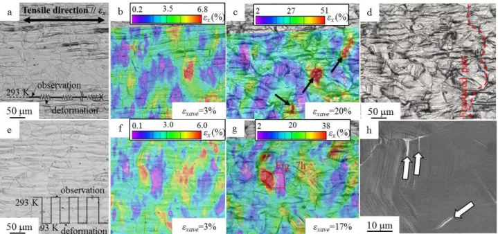
Figure S6 shows results of in situ optical microscopic observations with DIC and the corresponding images after
fracture in the Fe-
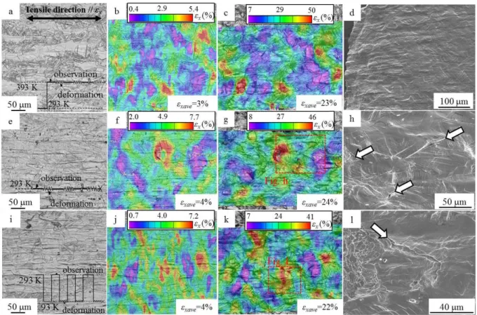
-martensite as random patterns, as shown in Figs. S6a, S6e, and S6i. Through Figs. S6a to S6 c, the deformation in
the Fe- -martensite
was present. In addition, river-like strain paths perpendicular to the tensile direction were observed, as shown in Fig. S6c. Despite the presence of strain localization, well-grown voids/cracks were not observed, even in the vicinity of the fractured part (Fig. S6d). Island-like strain localization features were observed in the Fe-28Mn alloy at 293 K (Figs. S6f and S6g). As shown in Fig. S6h, damage incidents were observed in the vicinity of boundaries between the island-like strain-localized and non-strain-localized regions. The strain localization and associated features of damage formation in the Fe-28Mn alloy at 93 K were similar to those at 293 K, but the damage incidents observed in the vicinity of the fractured part of the Fe-28Mn alloy at 93 K were larger than that at 293 K (Fig. S1).
The Fe-32Mn alloy showed strain localization at grain boundary triple junctions and in the vicinity of grain boundaries at 293 K, as shown in Figs. S7b and c. Figure S7c shows that a river-like strain path appeared and, correspondingly, fracture occurred in the vicinity of the river-like strain path, as indicated by the red dashed line in Fig. S7d. Figures 7e to h show that micro-cracks appeared in a vicinity of the boundary between strain-localization and non-strain-localization regions; that is, the crack initiation in the Fe-32Mn alloy at 93 K is also related to the strain localization. More specifically, the crack was initiated from grain boundary and propagated into the grain interior, as indicated by the arrows.
Fig. S6 Results obtained by in situ deformation experiments at (a d) 393, (e h) 293, and (i l) 93 K in the Fe-28Mn alloy. (a, e, i) Optical micrographs of the undeformed microstructures. The line diagrams indicate the procedure for the observation and subsequent deformation processes. Strain contour maps at cross-head
Fig. S7 Results obtained by in situ deformation experiments at (a d) 293 and (e h) 93 K in the Fe-32Mn alloy. (a, e) Optical micrographs of the undeformed microstructures. Strain contour maps at cross-head displacements
o Strain localization at a grain boundary triple junction
and near the grain boundary. (d) Optical micrograph at the
cross-path of fracture that was caused by subsequent deformation. (h) SE image of the fractured specimens, which correspond to the regions indicated by red dashed lines in (c, g). The arrows in the SE images indicate damage incidents.