Droplet Wettability and Impact Behavior on High-Temperature Microstructured Surfaces
(
高温微細構造表面上での液滴の濡れ性と衝突挙動)
January, 2019
Precision Machinery Engineering Major Graduate School of Science and Technology
Doctoral Course Nihon University
HAN YUXUAN
Contents
Chapter 1: Introduction: Wettability on the Microstructured Surface
Abstract 1
1.1 Wetting Phenomenon in Nature 2
1.2 Contact Angle and Hysteresis 7
1.3 Wetting Behavior on the Microstructured Surface 11
1.4 Creation of the Special Wettability Surface 14
1.5 Wettability measurements 17
1.6 Scope of This Thesis 19
Chapter 2: Profile Characterization and Temperature Effect on the Wettability of Microstructured Surfaces Abstract 24
2.1 Introduction 25
2.2 Theoretical Analysis 27
2.3 Experiments 28
2.3.1 Fabrication of Microstructured Surfaces 28
2.3.2 Contact Angle Measurement 33
2.4 Results and Discussion 34
2.4.1 Profile and Temperature Effect on Contact Angle 35
2.4.2 Shape and Temperature Effect on Contact Angle 38
2.5 Conclusions 40
Chapter 3: High temperature wettability on Microstructured Superhydrophobic Surface Abstract 41
3.1 Introduction 42
3.2 Theory and Calculation 44
3.3 Experimental Method 46
3.3.1 Microstructures Surface Design and Fabrication 46
3.3.2 Surface Characterization 47
3.3.3 Contact Angle Measurements 50
3.4 Results and Discussion 50
3.4.1 Profile and Temperature Effect on Contact Angle 50
3.4.2 Shape and Temperature Effect on Contact Angle 55
3.4.3 Droplet Stage Transition 59
3.5 Conclusions 61
Chapter 4: Thermodynamic Analysis on Wetting Behavior of the Microstructured Surfaces Abstract 63
4.1 Introduction 64
4.2 Theory and Calculation 66
4.2.1 Basic Theory 67
4.2.2 Analysis for Non-composite State 69
4.2.3 Analysis for Composite State 73
4.3 Results and Discussion 74
4.3.1 Effect of Pillar Height 74
4.3.2 Effect of Pillar Width 75
4.3.3 Effect of Space between Pillars 75
4.3.4 Scale Effect 76
4.4 Conclusions 77
Chapter 5: The Droplet Rebound Temperature on the Microstructure surfaces Abstract 78
5.1 Introduction 79
5.2 Experimental Methods 81
5.2.1 Surface Preparing and Measurements 81
5.2.2 High Speed Camera 82
5.3 Results and Discussions 83
5.3.1 Profile Characterization Effect 84
5.3.2 Shape Effect 87
5.4 Conclusions 89
Chapter 6: Outlook Abstract 91
6.1 General Recommendations and Outlook 92
References 93
Scientific Contributions 102
Acknowledgement 104
1
Chapter 1
Introduction: Wettability on the Microstructured Surface
Abstract
In this thesis, the wetting behaviors and droplet impact on the heated microstructured surface were investigated. In this chapter, the concepts of wettability and a short description of its history and growth were given.
The fabricate technology used in this thesis was detailed. The investigation on the static wettability and dynamic impact in this thesis could render an interesting candidate for application in microfluidics.
2 1.1 Wetting phenomenon in nature
The topic of wetting has received tremendous interest from both fundamental and applied points of view. It plays an important role in many industrial processes, such as oil recovery, lubrication, liquid coating, printing, and spray quenching [1–4].
Nature is a great genius to design the world with mystical principles, wetting is one of the omnipresent phenomena governed via the natural laws. Wetting is a common occurrence that many lives take advantage of in order to adapt to their living environment, such as the self-cleaning property of lotus leaves [5], the superior water-walking ability of water striders [6], the directional adhesion of butterfly wings [5,7], the antifogging functionality of mosquito eyes [8], the water collection of the Namib Desert beetle and spider silk [9,10], the submarine self-cleaning ability of fish scale [11], and the use of plastron respiration for underwater breathing [12]. There are a few examples presented in Fig.1.1.
(a) Leaf of Colocasia esculenta.
3 (b) Lotus leaf
(c) Leg of a water strider
(d) Surface of a mosquito eye
(e) Surface of butterfly wings
Fig.1.1 Some natural superhydrophobic materials, and their revealed by SEM[13,14]
200μm
4
Excited by these special properties of the natural creatures, the superhydrophobic/superoleophobic surface based on bionics has become a research hotspot. The large area superhydrophobic/superoleophobic surface has been produced extremely important application in industrial and agricultural production and people's daily life. For example, using a special process made of hydrophobic and oleophobic clothes not only stain fabrics to achieve long-term clean, but also effectively reduce the breeding of germs, therefore, people's daily lives has been brought great convenience; the non-stick pans made of PTFE with a special combination of lotus leaf microstructures have been a necessity in every kitchen due to their oleophobic property. Non-stick pans are not only easier to clean, but also greatly reduce the amount of used cooking oil and the cooking time. The application of self-cleaning materials to the curtain wall of the building surface can eliminate the need for manual and frequent cleaning, save a lot of cost and reduce safety hazards; for underwater transportation vehicles or underwater submarines, can reduce the resistance of the water, increases the speed of navigation and saves fuel. It can be seen that both daily life and national construction and even aerospace, super-hydrophobic/super-oleophobic surfaces have extremely wide application.
Human beings are always keen on understanding and imitating nature to improve our own society. From the pioneering work of Young
5
[15] and Laplace 200 years ago, many efforts have been devoted to explore the mechanism of wetting. The surface energy theory has well explained those static wetting phenomena mentioned above. Specifically, the value of contact angle among three phases is determined by Young-equation and the interface’s shape follows the Young-Laplace formula.
In recent years, there has been an increasing interest in the study of superhydrophobic surfaces, due to their potential applications in, for example, self-cleaning, nanofluidics, and electrowetting [16–20].
Usually superhydrophobic surface can be obtained by two ways:
One is to use chemical treatment to minimize the surface free energy of the material; the other is to increase the surface roughness of the hydrophobic material to increase the contact angle, or to combine the two to produce low surface energy and high roughness. More specifically, in the current research, there are mainly the following methods for making super-hydrophobic surfaces: Researchers created varies methods to fabricate the hierarchical structures such as lithography[21], electro deposition[22], chemical deposition[23], sputtering[24], anodization[25], and ultrafast laser surface texturing[26] on silicon[27], polymer[26, 28]
and metals[25, 29]. Superhydrophobic surface, typically an effect enhanced by surface roughness, has recently attracted great attention because of the easy fabrication of microstructured surfaces with
6 superhydrophobicity.
Many researchers create the various microstructures surfaces with special wettability.[11, 16, 19, 20, 30-33].
Quanshui Zheng [34] reported the superhydrophobic silicon surfaces were fabricated by Si ICP etching technology. The profile effect on the contact angle on the micro-pillar surface was analyzed. Tommaso Baldacchini [35] reported superhydrophobic silicon surfaces were prepared using high energy femtosecond pulsed laser processing techniques. Didem Oner [36] reported that a series of microstructures with different structural parameters are prepared on the surface of silicon by reactive ion etching. The surface is treated by silanization solution to obtain superhydrophobic properties of more than 170°. Changing the structural parameters for testing and comparison, the optimized parameters are obtained, and the water droplets are easily rolled on the surface. Hong Zhao [37] reported that the masked and Bosch etching method is used to etch a regular laminated trench structure on a silicon wafer, and the low surface energy modification is performed by using fluorosilane. The obtained grating microstructure silicon surface has superhydrophobic and self-cleaning performance.
Researchers created many special wettability surfaces. However, few researchers investigate the temperature affect coupled with microstructure.
But surface wettability at non-ambient temperature was of great
7
importance in many industrial processes, including water transportation and metal processing.[38, 39] Therefore, of temperature depended wettability on microstructured surfaces is important and imperative.
In this thesis, we will focus on investigation of the temperature and profile effect on the hydrophobic and superhydrophobic micro-pillar structured surfaces and the dynamic droplet impact behaviors on the heated micro-pillar structured surface.
1.2 Contact angle and hysteresis
Wettability studies usually involve the measurement of contact angles as the primary data, which indicates the degree of wetting when a solid and liquid interact. Small contact angles (<90°) correspond to high wettability, while large contact angles (>90°) correspond to low wettability (as shown in Fig.1.2).
Fig.1.2.Illustration of contact angles on a smooth homogeneous solid surface
Surface tension
Although liquid is easily deformed by external forces, the droplets are always tending to be a sphere somehow. This is because of surface
8
tension, which pulls the surface layer to make the exposed surface area as minimal as possible. This phenomenon can be viewed in the terms of energy: a molecule surrounded by neighbors on all sides is much more stable than the molecule that misses some neighbors. The force balance and unbalance are showed in Fig.1.3.
Fig.1.3. Diagram of the forces on molecules inside the liquid and on the interface Thus, the interior molecules has lower energy than the molecules at the interface between liquid and air. In order to minimize energy state and stabilize the whole system, the surface area is kept as small as possible, resulting in the spherical shape.
Equilibrium state and contact angle
Consider a liquid drop resting on a flat, horizontal solid surface (Fig.1.2). The contact angle is defined as the angle formed by the
9
intersection of the liquid-solid interface and the liquid-vapor interface (geometrically acquired by applying a tangent line from the contact point along the liquid-vapor interface in the droplet profile). The interface where solid, liquid, and vapor co-exist is referred to as the “three phase contact line”. Fig.1.2 showed that a small contact angle was observed when the liquid spreads on the surface, while a large contact angle is observed when the liquid beads on the surface. More specifically, a contact angle less than 90° indicates that wetting of the surface is favorable, and the fluid will spread over a large area on the surface; while contact angles greater than 90° generally means that wetting of the surface is unfavorable so the fluid will minimize its contact with the surface and form a compact liquid droplet.
For wetting, the discussion of the surface energy situation is more complicated than the free surface due to a third phase introduced. In this case, there are three kinds of interfaces: liquid-vapor (
γ
LV), solid- vapor (γ
SV) and solid-liquid (γ
SL). When a droplet stops on a flat substrate, it reaches its equilibrium state. Young’s equation[15] describes the equilibrium state in terms of force balance (as shown in Fig.1.2).cosθ=(
γ
SV-γ
SL)/γ
LV (1.1) Nevertheless, Young’s equation is only suitable for the surface which was ideal; that is to say, smooth and chemically homogeneous.
10 Contact angle hysteresis
From Young’s equation applied to a specific liquid-solid system, three thermodynamic parameters
γ
LV ,γ
SV, andγ
SL determine a single and unique contact angle θ. In practice, however, there exist many metastable states of a droplet on a solid, and the observed contact angles are usually not equal to θ. The phenomenon of wetting is more than just a static state. The liquid moves to expose its fresh surface and to wet the fresh surface of the solid in turn. The measurement of a single static contact angle to characterize wetting behavior is no longer adequate.(a) (b)
Fig.1. 4. (a) Advancing and (b) receding contact angles measurement using Increase/Decrease liquid Method
If the three-phase contact line was in actual motion, the contact angle produced was called a “dynamic” contact angle. In particular, the contact angles formed by expanding and contracting the liquid were referred to as the advancing contact angle θA and the receding contact angle θR, respectively (Fig.1.4). These angles fall within a range, with the
11
advancing angles approaching a maximum value, and the receding angles approaching a minimum value [40, 41]. The difference between the advancing angle and the receding angle is called the contact angle hysteresis (CAH):
θH=θA- θR (1.2) 1.3 Wetting behavior on the microstructured surface
In practice, solids are usually rough and heterogeneous, which therefore calls for more understanding of the influence of such surface characteristics on wetting and spreading. So far there are two standard models illustrating how the roughness or defects affect wetting properties:
Wenzel’s model and Cassie-Baxter model.
Wenzel’s model
In 1936, R. N. Wenzel reported a model [42] describing the influence of the roughness on wetting when all the surfaces are wet by fluid (Fig.1.5). In this model, it is assumed that the local contact angle θ is given by Young’s equation and the surface is rough but chemically homogeneous. When the roughness scale is much smaller than the droplet size, the apparent contact angle θa can be derived in the view of energy change as below. Considering a tiny displacement dx of the contact line in a direction of droplet spreading, the surface energies of the system changes as
dE=r(
γ
SL-γ
SV)dx+γ
LVdxcosθa (1.3)12
where r is the measure of roughness of the solid. In order to get the equilibrium state, dE is set as zero, leading to Wenzel’s relation:
cosθw= rcosθ (1.4) where θw is the contact angle of droplet tothe non-composite state where water penetrates into the gap space when a droplet on a rough surface.
Fig.1.5. Wenzel wetting state on solid Cassie-Baxter model
When the surface is made from or covered by two types of substances, Cassie-Baxter model [43] is applied to predict the contact angle on this composite substrate (Fig.1.6). There are several assumptions for the model to be applicable. Firstly, the surface is planar and each species is characterized by contact angle, which θ1 is for material 1 and θ2
for material 2. Secondly, the area fraction of each material is denoted as f1
and f2 for material 1and 2 respectively (f1 + f2=1). Thirdly, the individual
13
areas are much smaller than the size of droplet. Under this condition, the apparent contact angle can also be calculated by the energy variation relation.
dE = f1 (
γ
SL1-γ
SV1)dx + f2(γ
SL2-γ
SV2)dx +γ
LVdxcosθa (1.5) The minimum of dE, which is zero, defines equilibrium. By substituting Young’s equation into Eq. (1.5), Cassie-Baxter relation can be written as belowcosθa = f1 cosθ1 + f2 cosθ2 (1.6) Specifically, if one of the substances was air, the contact angle was 180°, leading to the equation given as
cosθc = f1 (cosθ + 1) – 1 (1.7)
Fig.1.6. Cassie-Baxter wetting state
14
1.4 Creation of the special wettability surface
The extraordinary water repellency showed by superhydrophobic surface could be attributed to the combination of biomimetic micro-nano hierarchical structures and low surface energies. A. Marmur puts the Wenzel and Cassie-Baxter equations into proper mathematical-thermodynamic perspective and defines the conditions for determining the transition between the homogeneous and heterogeneous wetting regimes [44]. As we introduced before, varies methods have been developed to create the hierarchical structures. Among of them, microfabrication recently attracted great attention because of the easy fabrication of microstructured surfaces with special wettability.
Microfabrication is the technology to fabricate miniature devices, which are made up of components generally ranging from 1 to 100um [45]. Recently in the MEMS field, burgeoning research efforts have been made to develop the fabrication methods so that obtaining my desired microstructures with accurate size on the silicon wafer is no longer a big problem. In this research, the photolithography and Si inductively coupled plasma (ICP) etching techniques are employed to fabricate the micro-pillar structured surfaces.
a) Photolithography process
A single iteration of photolithography combines several steps in sequence. The basic steps are photoresist spin-coated, exposure,
15 developing, and photoresist remove.
The Si surface is spin-coated with a particular kind of polymer, which can change its molecular properties after exposition to an electromagnetic radiation. A viscous, liquid solution of photoresist (S1815) is dispensed onto the wafer, and the wafer is spun rapidly to produce a uniformly thick layer. The spin coating runs at two steps, 500 rpm for 5 seconds, and 3000rpm for 30 seconds. The spin coating process results in a uniform thin layer, usually with uniformity of within 5 to 10 nanometers. This uniformity can be explained by detailed fluid-mechanical modeling, which shows that the resist moves much faster at the top of the layer than at the bottom, where viscous forces bind the resist to the wafer surface. Thus, the top layer of resist is quickly ejected from the wafer's edge while the bottom layer still creeps slowly radially along the wafer. In this way, any bump or ridge of resist is removed, leaving a very flat layer. Final thickness is also determined by the evaporation of liquid solvents from the resist.
The photoresist-coated wafer is then prebaked to drive off excess photoresist solvent, at 90 °C for 20 minutes in a bake oven. The final photoresist layer was approximate 1.5 microns thick.
After prebaking, the photoresist is exposed to a pattern of intense light. The optical lithography uses ultraviolet light that wave length is 486 nm (hg-g line). Since the photoresist used in this study is a positive
16
photoresist, the photoresist becomes soluble in the basic developer (MF-319) that contained tetramethylammonium hydroxide (TMAH) when exposed. The micro-pillar structure was optically defined on the photoresist using a mask.
b) Silicon etching
The silicon anisotropic etching using inductively coupled plasma (ICP) (STS MUC21) was performed using the Bosch process as described elsewhere [46]. The Bosh process employs alternative SF6 silicon etching and polymer deposition processes using C4F8 plasmas for the anisotropic etching of silicon.
For the ICP etching, the operating is that the Fluorine ions are accelerated in the electric field. Cause them to collide into the surface of the sample. A hard mask (aluminum layer or photoresist layer) is used to protect certain areas from etching, exposing only the areas desired to be etched. Another mechanism is sidewall passivation: deposition of a chemically inert passivation layer CxFy functional groups (C4F8 source gas yields a substance similar to Teflon) condensate on the sidewalls, and protect them from lateral etching. As a combination of these processes deep vertical structures can be made (see in Fig. 1.7).
The etching ions are accelerated into the etching region, where they combine with silicon and then are dispersed. Because the electric field accelerated ions toward the surface, the etching caused by these ions is
17
much more dominant than the etching of radicals - ions traveling in varied directions, and the sidewall passivation protect the sidewall well, so the etching are anisotropic.
Fig.1.7. Schematic of ICP etching process
1.5 Wettability measurements
1) Static contact angle measurements
Gas-liquid–solid interfaces of droplets on a micro-structured surface can be continuous in the single-phase regime. The temperature-dependent wettability of single-phase regime droplets was characterized using contact angle measurements. Contact angle (CA) measurements were
18
assessed at different temperatures with the KRUSS temperature controlled chamber TC21 for the temperature control of samples and Droplet Sharp Analyzer DSA25 for a contact angle measurement (as shown in Fig 1.8), which places a water droplet of 10 μL on the micro-structured substrate.
Fig 1.8 Contact angle measurement equipment (KRUSS DSA25 & TC21)
The temperature controlled chamber TC21 enables liquid and solid surfaces to be analyzed at temperatures up to 400 °C. The shown temperature is the sensor temperature on the top side of the microstructured surfaces. The target temperature is easy to specify and
Temperature sensor
Temperature controlled chamber Automatic syringe
Microstructured surfaces
19
reliably achieved at defined heating rates. The chamber’s excellent insulation ensures stable equilibrium during the measurement. An accurate temperature sensor is located on the top of surfaces to measure the actual temperature. With the help of the temperature sensor, the current value is recorded by the software together with the contact angle.
The used DI water (18.2 MΩ•cm) was purified in a DI water system.
The fabricated Si wafer was cleared by the RCA cleaning process before taking the contact angle measurement. The 10 μL DI water droplets were produced by the automatic controlled syringe. This automatic syringe was used to generate droplets with an injection rate of 0.15mL/min to reduce the inertial effects. The temperature of the droplet is 28 °C (room temperature). All the static contact angles are measured three times using the polynomial fitting method on each surface. In order to stabilize the surface temperatures, the interval between each measurement is 5 minutes at same surface temperature and 10 minutes when the surface temperatures are changed.
2) Droplet rebounded observing
For the droplet impact behaviors observing, the surface temperature and the water spreading or rebounding are recorded with a precise thermo sensor and a CCD, respectively. The injector was kept 20 mm higher than the heating surfaces to preserve the drop from heat. A 10 μL DI water
20
droplet was pushed out. The water droplet was well preserved before coming into contact with the high-temperature surfaces.
A Digital camera with high-speed model (Nikon1 J5) was employed to record the spreading and rebounding processes of impacting droplets from the side. From the side-view recording of each impact experiment, the droplet impact is measured.
1.6 Scope of this thesis
All the knowledge and models above shed light on the dominant mechanism of wetting, while the general theory still faces a great challenge for further insight. Moreover, the developing history is also a sign that the effects of topography is frequently overlooked, although we have learned that the geometry on substrates can strongly modify the properties of static wetting such as Cassie wetting state. However, few researchers investigate the surface temperature and topography effect on the wetting behaviors simultaneously.
Since temperature depended wettability on microstructured surfaces is important and imperative, we will investigate the temperature depended wettability of the hydrophobic and superhydrophobic micro-pillar structured surfaces and the dynamic droplet impact behaviors on the heated micro-pillar structured surface to obtaining controllable wettability on micro-structured surfaces at different surface temperature.
21
The wettability of surfaces is determined by surface temperature and roughness. In this thesis we study the static wetting properties at different temperatures and dynamic droplet impact on heated microstructured surface.
In Chapter 1 an introduction to the wettability and microfabrication, the main subjects in this thesis, is provided. The study of wettability on the solid surfaces is placed in a historic perspective and the fabrication process of the microstructures surfaces was shortly introduced.
In Chapter 2 Si wafers with various structures were fabricated to investigate wettability at different temperatures. Three shapes with micro-pillar structured surfaces were designed and fabricated.
Pillar-structured surfaces were fabricated by photolithography and ICP etching. The temperature-dependent wettability of single-phase regime droplets was characterized using contact angle measurements. The wetting behavior of a water droplet was observed.
Chapter 3 detailed the wettability of superhydrophobic surfaces at non-ambient temperature, especially at high temperature (30 to 90°C). In this chapter, Silicon wafers with various structures were fabricated to create superhydrophobic surfaces for investigating wettability at different temperatures. Four shapes micro-pillar structured surfaces were designed and fabricated by photolithography and ICP etching. The temperature-dependent wettability of single-phase regime droplets was
22
characterized using contact angle measurements on these surfaces. The surface temperature and pillar parameters driven Cassie-Baxter to Wenzel wetting transition are reported on superhydrophobic surfaces. The wetting behavior of a water droplet was observed to be different on the surfaces, and the wetting transition from Cassie-Baxter state to Wenzel state occurred at 70℃ on a special micro-pillar surface .
Chapter 4 focused on the thermodynamic mechanisms of superhydrophobicity affected by surface roughness. In this chapter, a 3-D square pillar-textured surface model was chosen to investigate the thermodynamic mechanism responsible for contact angle (CA), and free energy barrier (FEB). The effects of pillar width, space between pillars and pillar height on CA and FEB were obtained, and the calculated results are essentially consistent with the results of experimental measurement.
The present approach could provide a theoretical guidance for designing superhydrophobic surfaces.
Droplet impact experiments described in Chapter 5 on superheated silicon microstructured surfaces showed that the dynamic droplet rebound temperature, Tr. Two series of microstructured silicon surfaces which was decorated by micro-pillars whose pillar width, space between pillars and pillar height can be adjusted independently were fabricated. These surfaces possessed a hydrophobic/superhydrophobic property. The dynamic behavior of water droplets impacting these structured surfaces
23
was examined using a high-speed camera. Experimental results validated that the difference in the droplet rebound temperature was subjected to the solid fraction referred to as the ratio of the actual area contacting with the liquid to its projected area on the textured surface. Because the mechanism by which the residual liquid film emerges on the pillars’ tops can essentially be ascribed to the pinch-off of the liquid threads.
The microstructure on the solid surface affects the wettability surface, and the surfaces temperature also affects the wettability. The combination of these factors has brought many challenges to in-depth research, and we have been able to design more functional surfaces such as superhydrophobic surfaces to reduce flow resistance, wettability gradient surfaces to achieve self-driving of liquid droplets, separation and detection of substances on microfluidic surfaces for microfluidics. This thesis explores the interaction mechanism between solid and liquid by studying the special phenomena of droplets on different microstructures with difference temperature by experimental test and theoretical analysis.
This study may provide theoretical guidance for future research on micro-heat exchanger, microfluidic, micro-separator and the engine design.
24
Chapter 2
Profile Characterization and Temperature Effect on the Wettability of Micro-structured Surfaces
Abstract
In the nature world wetting is a common phenomenon. The effect of surface morphology and temperature effect on the wetting behavior at different temperature (30 °C to 90 °C) was an important research that had never been studied systematically. In this research, it was studied and investigated by using contact angle measurements. Three shapes of micro-pillar structured surfaces were designed and fabricated by photolithography and ICP etching to measure the contact angles. The wetting behavior of the water droplet was observed and the regular patterns were concluded at the end.
25 2.1. Introduction
There are lots of wetting phenomenon in our environment including the plants and living beings. They have their special characteristics to protect themselves and adapt to the circumambient surroundings [47-51].
The mosquito eyes which have special nanometer structure can resist the wetness of fogging outside [50]. Also, the lotus leaves have fuzz like micro structure which can cause the droplet rolling down, so that it has self-cleaning property. It is important on the research of wetting to inhibit corrosion and enhance the coefficient of utilization on material [5].
The studies in controlling the surface texture and properties become much more important since wenzel effect which was reported on surface wettability of roughness [42]. The researchers are doing the research on modifying the surface roughness to enhance the surface wetting. So far, lots of researchers are doing the research focus on the wetting influence of micro structured surfaces [52], but the complexity influence including the temperature and micro-structured surface influence hasn’t been discussed yet. The combination of temperature effects and micro-structure influence had been researched in this thesis.
There are two kinds of states when the droplets drip on the micro-structured surface [32]. They are Wenzel state (non-composite state) (Fig.2.1(a)) and Cassie-Baxter state (composite state) (Fig.2.1(b)).
Wenzel state is the surface completely covered with droplet and no air
26
between the liquid and solid. In Wenzel’s proposal, it was described when the micro-structured surface is completely wetting the droplet contact angle is influenced by the increase of the wetted area. Cassie-Baxter state is the droplet contact part of the solid and the air is left between the solid and liquid. The micro-structured surface including the hydrophilic [33]
and hydrophobic [53, 54] become much more important in the research of wetting.
On the high temperature (30 °C to 90 °C) the wettability is much important in the industry process [55]. There are lots of influence in surface wettability such as the nucleate boiling based on the lyophilic micro-structured surface leads high critical heat flux [56], the hot water repellent in super-hydrophobic surface [57], wetting transition on hydrophobic microstructured-surface during evaporation [58–60], the fabrication of wetting-controllable thermally responsive materials [61, 62], low temperature heat exchange on hydrophobic surfaces [63] and so on. It is important in water transportation and metal processing in industrial processes especially at high temperature (30 °C to 90 °C) [38].
The theory and applications of droplet wetting behavior on hot surfaces in the solid–liquid heat transfer system become much more important [64].
27
(a) Wenzel state
(b) Cassie-Baxter state Fig.2.1. States of droplets on the micro-structured surface.
So far, there is not a systematically description on wetting of temperature effect and micro-structured surface. In this research, three kinds of micro-structured surfaces were designed to research the surface wetting behavior in different temperatures from 30 °C to 90 °C.
Photolithography and ICP etching were used to fabricate the silicon wafer.
The characteristics of wetting with various micro-structured surfaces in different temperatures were researched and studied.
2.2. Theoretical Analysis
Fig.2.2. Illustration of the contact angle.
The Young equation [15] showed the relationship of the contact angle
28 θ on a smooth surface.
cosθ=(
γ
SV-γ
SL)/γ
LV (2.1) In the equation,γ
SV is the surface tension coefficient on solid-vapor interface.γ
SL is surface tension coefficient on solid-liquid interface.γ
LV is surface tension coefficient on liquid-vapor interface。The contact angle θ has the relation with the droplet state both the Wenzel state and Cassie-Baxter state. The equation of contact angle θ was described by Cassie and Baxter [43] as follows.
cosθc=(
γ
*SV -γ
*SL)/γ
LV (2.2) In this equation:γ
*SV =fγ
SV ;γ
*SL =(1-f)γ
LV+fγ
SL. f is the area fraction.There is another model and equation to describe the contact angle θ on a rough surface as there are three-phase contact line tension on the liquid-vapor-solid phase boundary [65-67]. In this equation, λ is the line tension and K is the influence coefficient of scale effect.
cosθc*=-1+(1+cosθ)(1 - -λ/(K(1+cosθ)
γ
LV ))f (2.3) where λ is the line tension and K is the influence coefficient of scale effect.2.3. Experiments
2.3.1. Fabrication of Micro-Structured Surfaces
In this research, three shapes of micro-pillar structured surfaces were
29
designed and fabricated to investigate the wettability in different temperatures from 30 °C to 90 °C. The pillar-structured surfaces were fabricated by photolithography and inductively coupled plasma (ICP) etching. These micro-pillars were uniformly distributed in a rectangular grid on a glass mask with different values of the area fraction f.
During the fabrication, The Silicon wafer ((100), 4 Inch, 400μm thick, p-type) were used. Firstly, clear and dry the wafer in the clean room and then coated with positive photoresist (S1805) by a spin-coater. Next, transfer the required pattern from the mask to the photoresist layer by UV exposure. Then the photoresist was partly removed in the developer.
Finally, the ICP etcher was used to etch the uncovered Si wafer to fabricate the roughness pattern on it. Then clear away the residual photoresist by the acetone. The etching experiments were performed in the STS ICP system.
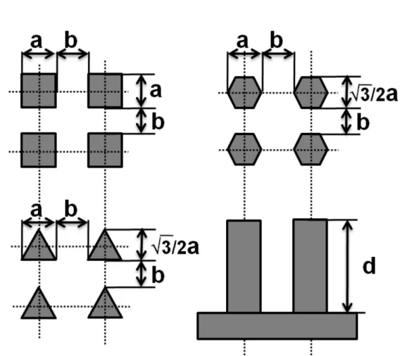
In the designing, three shapes of micro-pillars are square pillars, triangle pillars and hexagon pillars. The side length of the square and triangle pillars were 10 μm and the hexagon pillars’ side length was 5 μm.
It was shown in Fig.2.3 and the parameters of these three geometric patterns were shown in Table 1. The pillar height d were 10 μm and 20 μm. It could be acquired by controlling the etching circles during the ICP etching.
30
Table 2.1. Characterization of Microstructure Geometric Parameters.
Shape of micro pillar Area fraction f K
Square a2
(a + b)2
a 4
Triangle √3a2
(√3a + 2b)2
√3
Hexagon 3√3a2 12 a
2(√3a + b)(2a + b)
√3 4 a
Fig.2.3. Microstructure distribution diagram
The fixed pillar heights (d = 10 μm and 20 μm) for all the pillar-structured surfaces was achieved by controlling the etching circles.
The fabricated micro-structured surfaces were measured by the Confocal Laser Scanning Microscope (CLSM),LEXTOLS4000, OLYMPUS. The
31
fabricated micro-pillars’ parameters and profiles were shown in Table 2.2, Table 2.3, and Fig.2.4. The fabricated microstructures have a small amount of manufacturing error in the mask error and fabrication process, but the error was within a reasonable error range.
Table 2.2. Actual measured parameters of microstructure with d = 10 μm
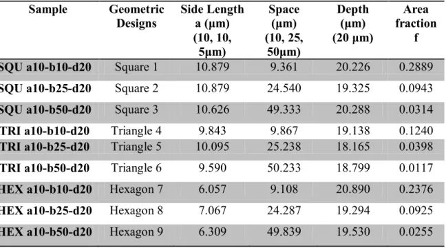
Table 2.3. Actual measured parameters of microstructure with d = 20 μm Sample Geometric
Designs Side Length a (μm) (10, 10, 5μm)
Space (μm) (10, 25,
50μm)
Depth (μm) (20 μm)
Area fraction
f SQU a10-b10-d20 Square 1 10.879 9.361 20.226 0.2889 SQU a10-b25-d20 Square 2 10.879 24.540 19.325 0.0943 SQU a10-b50-d20 Square 3 10.626 49.333 20.288 0.0314 TRI a10-b10-d20 Triangle 4 9.843 9.867 19.138 0.1240 TRI a10-b25-d20 Triangle 5 10.095 25.238 18.165 0.0398 TRI a10-b50-d20 Triangle 6 9.590 50.233 18.799 0.0117 HEX a10-b10-d20 Hexagon 7 6.057 9.108 20.890 0.2376 HEX a10-b25-d20 Hexagon 8 7.067 24.287 19.294 0.0925 HEX a10-b50-d20 Hexagon 9 6.309 49.839 19.530 0.0255
Sample Geometric
designs Side length a (μm) (10, 10, 5
μm)
Space b (μm) (10, 25,
50μm)
Depth d (μm) (10μm)
Area fraction f
SQU a10-b10-d10 Square1 10.120 9.986 10.882 0.2533 SQU a10-b25-d10 Square2 9.933 24.540 12.415 0.0838 SQU a10-b50-d10 Square3 9.867 49.333 14.694 0.0278 TRI a10-b10-d10 Triangle 4 10.373 10.373 12.656 0.1244 TRI a10-b25-d10 Triangle 5 9.867 25.299 11.147 0.0268 TRI a10-b50-d10 Triangle 6 9.614 50.345 11.868 0.0116 HEX a10-b10-d10 Hexagon 7 5.819 9.590 15.251 0.2107 HEX a10-b25-d10 Hexagon 8 5.819 25.046 12.715 0.0683 HEX a10-b50-d10 Hexagon 9 6.072 49.586 13.244 0.0258
32
Fig.2.4. Three-dimensional images of micro-pillars with designed h = 20 μm, (1), (2), and (3) shown the a = 10 μm square micro-pillar structures with different space between the pillars, b = 10 μm, 25 μm, and 50 μm respectively. (4), (5), and (6) shows the a = 10μm triangle micro-pillar structures with different spaces between the pillars.
b = 10 μm, 25 μm, and 50 μm respectively. (7), (8), and (9) shown the a = 10 μm hexagon micro-pillar structures (Side length = 5 μm) with different space between the pillars b = 10 μm, 25 μm, and 50 μm, respectively
As the roughness would influence the droplet contacting the surface of micro-pillar, it’s an important parameter on the micro-pillar top and were observed by the Confocal Laser Scanning Microscope (CLSM) and Atomic Force Microscope (AFM). The top surface on the micro-pillar
33
had a root mean square roughness of 0.433 nm (5μm X 5μm) (as shown in the Fig.2.5) and was relatively smooth. It could be neglected in the contact angle test. Also, the surface roughness Ra of the bottom etched Si surface was approximately 0.2 μm.
Fig.2.5. Morphology of the micro-pillar top surface. (a) CLSM image of the square micro-pillar. (b), (c) AFM images of the typical topography of the micro-pillar top surface (5μm X 5μm). The root mean square roughness is 0.433nm.
2.3.2. Contact Angle Measurement
The relationship of vapor, liquid and solid of droplet could be described in single-phase regime. Contact angle measurements could be used to describe the temperature-dependent wettability of single-phase regime droplets. During the contact angle (CA) measurement the KRUSS temperature controlled chamber TC21 was used to control the
(a) (c) (b) Top of micro-pillar
34
temperature. The Droplet Sharp Analyzer DSA25 was used to place a 10-μL-water droplet on the micro-structured substrate. (volume for a drop to not be affected by gravity)
During the measuring, a range of contact angles would be obtained. At the advancing edge of a liquid drop, the upper limit of the range was obtained which is the advancing contact angle θA. At the receding edge, the lower limit of the range was obtained which is the receding contact angle θR.
In the research, the used DI water (18.2 MΩ•cm) was purified in a DI water system. The fabricated Si wafer was cleared by the RCA cleaning process before taking the contact angle measurement. The static advancing and receding contact angles were measured three times by using the polynomial fitting method on each surface. The advancing and receding angles were measured by slowly pumping liquid into or out of a droplet. The used DI water (18.2 MΩ•cm) was purified in a DI water system. The fabricated Si wafer was cleared by the RCA cleaning process before taking the contact angle measurement.
2.4. Results and Discussion
There were lots of contact angles (CA) during the measurement on the micro-structured surface. But a drop should have a stable point at the energetically lowest point. It was named equilibrium CA.
35
During the research, all the droplets were Cassie-Baxter state on the micro-structured surfaces but the droplet on the square-pillar surface with pillar space b=50 μm and pillar height d=10 μm were at 50 °C.
The measurement result data of the advancing and receding contact angles could be used to calculate the equilibrium CA by using the Tadmor equation [68]. The hysteresis was determined by some dimensionless parameter which was normalized line energy.
𝜃 = arccos�𝜏𝐿𝑐𝑐𝑐𝑐𝜏𝐿+𝜏𝑅𝑐𝑐𝑐𝑐𝑅
𝐿+𝜏𝑅 � (2.4) where 𝜏𝐿 ≡ �(2−3𝑐𝑐𝑐𝑐𝑐𝑠𝑠3𝑐𝐿
𝐿+𝑐𝑐𝑐3𝑐𝐿)�1 3⁄ and 𝜏𝑅 ≡ �(2−3𝑐𝑐𝑐𝑐𝑐𝑠𝑠3𝑐𝑅
𝑅+𝑐𝑐𝑐3𝑐𝑅)�1 3⁄
2.4.1. Profile Characterization and Temperature Effect on Contact Angle From the measuring data, the CAs were lager on the micro-structured surfaces than the smooth surface as the roughness enhances the wetting.
The profile characterization effects on the micro-surface were shown in the Fig.2.6.
The contact angles on the micro-structured surface with different temperatures (30 °C to 90 °C) were shown in Fig.2.6. From the Figures, several effects could be concluded as following:
The CAs and area fraction f decreased when the space between the pillars became wider.
36
The pillar height’s increasing leads to the equilibrium CA increases.
With the pillar height increases the equilibrium CA increases.
The CAs decreases when temperature increases with pillar height 20 μm.
From the Fig.2.6(a) and (b), for the hexagon micro-pillars, the CAs with the higher micro-pillars were more lineally with temperature increasing.
The air layer in the micro-pillars buffered the temperature effect. With square and triangle micro-pillars, the similar results were shown on the square and triangle micro-pillar surface.
With the 10 μm pillar height and the CA curve of the micro-pillar surface with space b 10 μm, it rose first and then went down when the sample was heated. The same result as the CA curves of the hexagon- and triangle-pillar surfaces with space b were 20 μm.
But CA curves of the surface with square-pillars showed the opposite way. It went down first and then rose.
With the space b was 50 μm, the CA curve of these micro-pillar surfaces showed the lineal change as the temperature increased. This phenomenon caused by heated air layer in the micro-pillars and the temperature affected surface tension coefficients
37
(a) (b)
(c) (d)
(e) (f)
Fig.2.6. Contact angle curve of the same shape’s micro-structured surface at different temperatures. (a) and (b) show the contact angles at different temperatures on the hexagon micro-pillar surfaces with d = 10 μm and 20 μm respectively. (c) and (d) shows the contact angles at different temperatures on the square micro-pillar surfaces with d = 10 μm and 20 μm respectively. (e) and (f) shows the contact angles at different temperatures on the triangle micro-pillar surfaces with d = 10 μm and 20 μm, respectively.
38
2.4.2. Shape and Temperature Effect on Contact Angle
From the Fig.2.7, several effect could be concluded as following:
On these three shapes the CAs were first increased and then decreased.As the obtuse angle may avoid the stress concentration on the solid-liquid contact line, the Hexagon-pillar and Square-pillar micro-structured surfaces showed the higher CA when the parameters were the same.
With the temperatures went higher, the micro-pillar structured surfaces with the space between the pillars b = 10 μm decreased.
This phenomenon reduces rapidly when the space between the pillars increases, but this was nearly invisible in the CA measurements on the micro-structured surface with a pillar depth of d = 20 μm.
From Fig.2.7 (c) and (e), it was shown that the Hexagon-pillar surface has higher CA than the other two type micro-structured surfaces with space between the pillars b = 25 μm and 50 μm and pillar depth was 10 μm. when pillar depth was 20 μm, the CA on Square-pillar surface with pace between the pillars b = 10 μm and 25 μm was higher (see Fig.2.7 (b), (d)).
With the space between the pillars b = 10 μm and pillar depth d = 10 μm, the CA on triangle-pillar surface went down when the temperature rose over 40 °C. On the Square- and Hexagon-pillar surface, the CA went down from 70 °C and 60 °C respectively (Fig. 2.7(a)).
39
(a) (b)
(c) (d)
(e) (f)
Fig.2.7. Contact angle curve of the same designed parameter’s micro-structured surface at different temperatures. (a), (c), and (e) show the contact angles at different temperatures on the three shapes with micro-pillar surfaces with space b = 10 μm, 25 μm, and 50 μm respectively when the depth d = 10 μm. (b), (d), and (f) show the contact angles at different temperatures on the three shapes with micro-pillar surfaces and space b = 10 μm, 25 μm and 50 μm respectively when the depth d = 20 μm.
40 2.5. Conclusions
In this research three shapes of micro-pillar surfaces were designed with different space and height. They were successfully fabricated by using photolithography and ICP etching techniques. 10 μL DI water droplet was used to be observed the wetting behavior on the fabricated surfaces. The wetting behavior of surfaces with different micro-structures from 30 °C to 90 °C was described in this paper. From the measurement result, all the droplets were Cassie-Baxter state on the micro-structured surfaces except the droplet on the sample SQU a10-b50-d10 at 50 °C.
There were several conclusions from the observation and the primary conclusions are as follows:
The contact angles increased when the pillar height increased.
With the wider pillar-structure space the contact angle decreased.
With the pillar height 10 μm, the CAs were first increased and then decreased when the temperature rose.
The relationship of temperature and CAs on the micro-structured surfaces with pillar height d=20 μm was nearly linearly dependent.
On all the three-phase contact line, the contact angles were fluctuated by both the temperature change and the microstructure effect.
41
Chapter 3
High Temperature Wetting Transition on Microstructured Superhydrophobic Surface
Abstract:
Superhydrophobic surface has attracted significant attention since their potentiality to industrial and academic applications. Moreover, superhydrophobic surface wettability at non-ambient temperature, especially at high temperature (but not boiling) was of great importance in many industrial processes. In this paper, we designed and fabricated 4 series superhydrophobic micro-pillar surfaces on the Silicon wafers to investigate wettability at different temperatures. These micro-pillar surfaces were fabricated by photolithography and ICP etching technologies. The temperature-dependent wettability of DI water droplets was characterized using contact angle measurements. The wetting behavior was observed to be different on the surfaces, and the wetting transition occurred at a specific temperature.
42 3.1. Introduction
Inspired by the natural phenomena such as self-cleaning property on lotus leaves and fish scale [5, 11, 48], directional adhesion on butterfly wings [49], water striders walking on the water surface [6] antifogging of mosquito eyes [50], Wetting of superhydrophobic surfaces has received significant attention from both academic and industry due to their spectacular advantage and wide application such as self-cleaning materials[16], water collecting means[9], friction drag reduction surfaces[69],oil\water separation[70], and droplet control in microfluidic device [71]. The superhydrophobic surface with contact angle (CA) >
150◦and sliding angle (SA) below 10◦ was recognized as “lotus effect”, on which the droplets maintain a spherical shape and roll off easily.
Various methods had been developed to generate the superhydrophobic surfaces on glass, semiconductors, polymers and metals by using physical and chemical treatment.
Since Wenzel and Cassie reported the effect of roughness on surface wettability [42, 43], research found the way to enhance the wetting by modifying the surface roughness. Researchers created varies methods to fabricate the hierarchical structures such as lithography[72], electro deposition[22], chemical deposition[23], sputtering[24], anodization[25], and ultrafast laser surface texturing[73]. Superhydrophobic surface, typically an effect enhanced by surface roughness on hydrophobic
43
surfaces, has recently attracted great attention because of the easy fabrication of microstructured surfaces with superhydrophobicity.
Droplets on chemically or microstructured surfaces can generally adopt two different states[54]: the Wenzel state, in which the liquid completely wets the entire surface (see Fig.3.1(a)), or the Cassie-Baxter state, in which the droplet only partly wets the surface, leaving air in between the microstructures under the droplet (see Fig.3.1(b)).
(a)Wenzel state (b)Cassie-Baxter state Fig.3.1. States of droplets
Moreover, surface wettability at high temperature (30 to 90℃), is importance in industrial processes[55], such as water transportation and metal processing [38]. Recently, several advances have been made, like the superhydrophobic surfaces hot water repellent [56], the wetting-controllable thermally responsive materials fabrication [58, 59], wetting transition on hydrophobic microstructures surface during
44
evaporation[60], low temperature heat exchanging on hydrophobic surfaces[63]. The theory and applications of droplet wetting behavior on a hot surface is very important in the solid–liquid heat transfer system[64].
However, the effect of surface morphology and temperature effect on the wetting behavior at high temperature as not been studied systematically. The investigation of the wetting behavior of surfaces with different micro-structures from 30 to 90℃ was described in this paper.
The goal of the present study was to investigate the effects of surface microstructure and temperature on the superhydrophobic surfaces. Four shapes micro-pillars with deferent distributed parameters microstructured surfaces with different wettability Silicon wafer were fabricated to investigate wettability at different temperatures. Wafers with micro-pillars arrays were obtained by photolithography and ICP etching.
3.2. Theory and calculation
Fig.3.2. Illustration of the contact angle
45
The contact angle of a water droplet on a smooth and chemical homogeneous surface (as shown in Fig.3.2) can be computed by the Young’s equation [15].
cosθ = γSVγ−γSL
LV (3.1) where
γ
SV,γ
SL andγ
LV, are the surface tension coefficients on solid-vapor, solid-liquid, and liquid-vapor interfaces, respectively.Both the Wenzel and Cassie-Baxter state has the following relation with the intrinsic contact angle θ and the topography of the roughness structure. Wenzel’s theory described the non-composite state where water penetrates into the gap space when a droplet on a rough surface [12].
cosθw= rcosθ (3.2) Cassie’s theory related to the composite state where the droplet on a rough surface traps air between solid and liquid. The wetting characteristic of such a surface was first addressed by Cassie and Baxter [13] and the apparent contact angle θc was predicted by the following equation.
cosθc=(
γ
*SV -γ
*SL)/γ
LV (3.3) whereγ
*SV =fγ
SV andγ
*SL =(1-f)γ
LV+fγ
SL, f is the area fraction.Researchers considered the three-phase contact line tension on the liquid-vapor-solid phase boundary and presented a new model to predict the contact angle of a water droplet on a rough surface.
cosθc*=-1+(1+cosθ)(1 - -λ/(K(1+cosθ)
γ
LV ))f (3.4)46
It was clear that the surface roughness can greatly influence the behavior of water drop on solid surface. On one hand, rough-ness increases the surface area of the solid, which geometrically enhances hydrophobicity (Wenzel state). On the other hand, vapor can remain trapped below the drop, which also leads to a superhydrophobic behavior, because the drop sits partially on vapor (Cassie- Baxter state).
3.3 Experimental Method
3.3.1 Microstructures Surface Design and Fabrication
Silicon wafer with various structures were fabricated to investigate wettability at different temperatures. 5-μm-level micro-pillars were uniformly distributed in a designated section with different space between the pillars.
Fig.3.3. Microstructure distribution diagram
47
The micro-structured surfaces were fabricated employed the photolithography and Inductively Coupled Plasma (ICP) etching techniques. The side lengths or diameter of these micro-pillars a = 5 μm(for Triangle-, Square-, and Circle-pillars) and the diagonal of hexagon-pillars a= 5 μm (side length a= 2.5μm for Hexagon-pillars ), as shown in Fig.3.3. These four-type pillars are uniformly distributed in a rectangular grid with four different spaces between the pillars for each shape pillar. The values of the space b= 5, 12.5, 25 and 50 μm. Two fixed pillar height (etching depth) d = 5 and 10 μm was achieved by controlling the etching parameter and time.
These micro-pillars were uniformly distributed in a square grid on a glass mask. Before the fabricating process, a 400 μm thick 4 inch Silicon wafer ((100), p-type) was cleaned in RCA process rinsed by the DI water and dry, then a 1μm positive photoresist layer (s1805) was spinning-coated on the Si surface. In the next step, the required pattern was transferred from the mask to the photoresist layer by UV exposing;
subsequently the photoresist was partly removed by the developer. The uncovered Si was etched in the ICP etcher (STS MC21) to finally fabricate the roughness pattern on the Si wafer.
3.3.2 Surface Characterization
Before the contact angle testing, the surface was cleaned in a RCA
48
process again, then rinsed with DI water and dried. The fabricated micro-pillars’ parameters and profiles were shown in the table 3.1 and 3. 2.
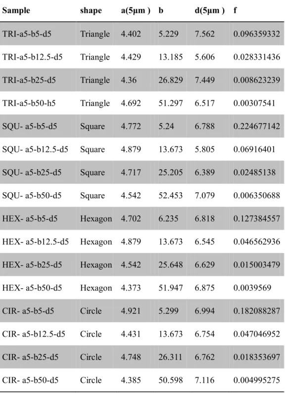
Table 3.1. Actual measured parameters of microstructure with d = 5 μm Sample shape a(5μm ) b d(5μm ) f
TRI-a5-b5-d5 Triangle 4.402 5.229 7.562 0.096359332 TRI-a5-b12.5-d5 Triangle 4.429 13.185 5.606 0.028331436 TRI-a5-b25-d5 Triangle 4.36 26.829 7.449 0.008623239 TRI-a5-b50-h5 Triangle 4.692 51.297 6.517 0.00307541 SQU- a5-b5-d5 Square 4.772 5.24 6.788 0.224677142 SQU- a5-b12.5-d5 Square 4.879 13.673 5.805 0.06916401 SQU- a5-b25-d5 Square 4.717 25.205 6.389 0.02485138 SQU- a5-b50-d5 Square 4.542 52.453 7.079 0.006350688 HEX- a5-b5-d5 Hexagon 4.702 6.235 6.818 0.127384557 HEX- a5-b12.5-d5 Hexagon 4.879 13.673 6.545 0.046562936 HEX- a5-b25-d5 Hexagon 4.542 25.648 6.629 0.015003479 HEX- a5-b50-d5 Hexagon 4.373 51.947 6.875 0.0039569 CIR- a5-b5-d5 Circle 4.921 5.299 6.994 0.182088287 CIR- a5-b12.5-d5 Circle 4.431 13.673 6.754 0.047046952 CIR- a5-b25-d5 Circle 4.748 26.311 6.762 0.018353697 CIR- a5-b50-d5 Circle 4.385 50.598 7.116 0.004995275
49
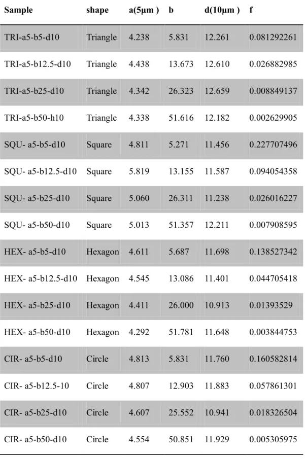
Table 3.2. Actual measured parameters of microstructure with d = 10 μm Sample shape a(5μm ) b d(10μm ) f
TRI-a5-b5-d10 Triangle 4.238 5.831 12.261 0.081292261 TRI-a5-b12.5-d10 Triangle 4.438 13.673 12.610 0.026882985 TRI-a5-b25-d10 Triangle 4.342 26.323 12.659 0.008849137 TRI-a5-b50-h10 Triangle 4.338 51.616 12.182 0.002629905 SQU- a5-b5-d10 Square 4.811 5.271 11.456 0.227707496 SQU- a5-b12.5-d10 Square 5.819 13.155 11.587 0.094054358 SQU- a5-b25-d10 Square 5.060 26.311 11.238 0.026016227 SQU- a5-b50-d10 Square 5.013 51.357 12.211 0.007908595 HEX- a5-b5-d10 Hexagon 4.611 5.687 11.698 0.138527342 HEX- a5-b12.5-d10 Hexagon 4.545 13.086 11.401 0.044705418 HEX- a5-b25-d10 Hexagon 4.411 26.000 10.913 0.01393529 HEX- a5-b50-d10 Hexagon 4.292 51.781 11.648 0.003844753 CIR- a5-b5-d10 Circle 4.813 5.831 11.760 0.160582814 CIR- a5-b12.5-10 Circle 4.807 12.903 11.883 0.057861301 CIR- a5-b25-d10 Circle 4.607 25.552 10.941 0.018326504 CIR- a5-b50-d10 Circle 4.554 50.851 11.929 0.005305975
50 3.3.3 Contact Angle Measurements
Contact angle (CA) measurements were realized at different temperatures with the KRUSS temperature controlled chamber TC21 for temperature control of samples and Droplet Sharp Analyzer DSA25 for contact angle measurement. The 10 μL DI water droplets were produced by the automatic controlled syringe. This automatic syringe was used to generate droplets with an injection rate of 0.15mL/min to reduce the inertial effects. All the static CAs were measured three times using the polynomial fitting method on each surface.
3.4 Results and Discussion
3.4.1 Profile and Temperature Effect on Contact Angle
The wetting behavior of these fabricated surfaces at various temperatures was investigated. The static contact angles were measured three times on each type surface. The results were shown in the following Figures. The error bars were undetectable in some figures since the deviation was less than 3°.
Fig.3.4 (a) and (b) showed the contact angles (CAs) on Circle-pillar surfaces with different area fraction f at various temperatures. The superhydrophobic wettability was observed on the Circle-pillar surfaces with pillar height d=5 and 10μm at the room temperature except the surface named Cir a5-b50-d10. Then these surfaces were heated using a