STUDY OF A ROCKFALL PROTECTIVE FENCE BASED ON BOTH EXPERIMENTAL AND NUMERICAL APPROACHES
著者 トラン バン プク
著者別表示 Tran Van Phuc journal or
publication title
博士論文本文Full 学位授与番号 13301甲第3963号
学位名 博士(工学)
学位授与年月日 2013‑09‑26
URL http://hdl.handle.net/2297/39366
Creative Commons : 表示 ‑ 非営利 ‑ 改変禁止 http://creativecommons.org/licenses/by‑nc‑nd/3.0/deed.ja
i
Abstract
The imperative need to protect structures in mountainous areas against rockfall has led to the development of various protection methods. This study introduces a new type of rockfall protection fence made of posts, wire ropes, wire-netting and energy absorbers. The performance of this rock fence was verified in both experiments and dynamic finite element analysis. In collision tests, a reinforced-concrete block rolled down a natural slope and struck the rock fence at the end of the slope. A specialized system of measuring instruments was employed to accurately measure the accelera- tion of the block without cable connection. In particular, the performance of two types of energy absorber, which contribute also to preventing wire ropes from breaking, was investigated to determine the best energy absorber. In numerical simulation, a commercial finite element code having explicit dynamic capabilities was employed to create models of the two full-scale tests. To facilitate simulation, certain simplifying assumptions for mechanical data of each individual component of the rock fence and geometrical data of the model were adopted. Good agreement between numerical simulation and experimental data validated the numerical simula- tion. Furthermore, the results of numerical simulation helped highlight limitations of the testing method. The results of numerical simulation thus provide a deeper under- standing of the structural behavior of individual components of the rock fence during rockfall impact.
In addition, a modified prototype is introduced as a developed prototype of the wire-
rope fence. The cost-reducing modifications are increased post spacing and fewer
wire netting layers. The numerical procedure again provides the nonlinear response
of the prototype under various impact conditions and insights into each component’s
role in dissipating impact energy. Furthermore, a simple but effective method of
increasing fence resistance is developed from analysis. Finally, the practical applica-
tion of two units of the prototype to protect a wide area is investigated employing the
numerical procedure.
ii
Acknowledgments
From the bottom of my heart, I would like to express my honest gratitude and high appreciation to my academic supervisor, Professor Koji Maegawa, for his continuous supports and kind encouragements, which strongly inspire me during the journey of doctoral course at Kanazawa University and successfully drive me to the end of the journey. The outstanding directions from him that I was guided at the every stage of my study will stand before me throughout my professional carrier in future.
I would like to extend my great thanks to Vietnamese government, Ministry of Education and Training for providing financial support during entire period of study.
Sincere appreciations are due to Raiteku Company. My study would not be complet- ed without the enormous supports from the company for full-scale tests that are key portion in my study. I also wish to express my deepest gratitude to Kanazawa Uni- versity as well as all members of Student Affair, who enthusiastically helped me since the beginning of my study and also the family life in Kanazawa.
I am extremely thankful to Mr. Yukio Abe and Mr. Mi Tetuo, who kindly helped me and my family since I started new life in Japan. I also would like to extend my special thanks to my dear friends and laboratory mates who assisted me directly or indirectly in both my study and daily life. For those I could not name them all, and for this purpose let me appreciate them.
I honestly express my deepest respect and extreme gratitude to my dear parents,
brothers, sisters, beloved wife and my son for their patience, unconditional love, and
support, strongly inspired me to accomplish my study.
iii
Contents
Abstract i
Acknowledgments ... ii
Chapter 1 Introduction ... 1
1.1 General Background - Literature Review ... 1
1.1.1 Rockfall Phenomenon: Definition and Types of Rockfall ... 1
1.1.2 Rockfall Causes ... 2
1.1.3 Setbacks of Rockfall Hazards ... 4
1.1.4 Rockfall Basic Knowledge ... 5
1.1.5 Rockfall Mitigation ... 7
1.1.6 Flexible Fences ... 8
1.2 Objectives and Scope of the Study ... 11
1.3 References ... 13
Chapter 2 Experiments on a Wire-Rope Rockfall Protective Fence... 18
2.1 Introduction ... 18
2.2 Configuration of the Rock Fence ... 20
2.2.1 Details of the Rock Fence ... 20
2.2.2 Experimental Control System ... 22
2.3 Outline of the Experiments ... 23
2.3.1 Pre-testing and Results for Energy Absorbers ... 23
2.3.2 Test of the Rock Fence ... 25
2.4 Results of Rock Fence Tests ... 26
2.4.1 Behavior of the Rock Fence ... 26
2.4.2 Impact Deceleration, Force, Velocity, and Energy ... 29
2.5 Conclusion ... 31
2.6 References ... 32
Chapter 3 Dynamic Finite Element Analysis on a Wire-Rope Rockfall
Protective Fence ... 33
iv
3.1 Introduction ... 33
3.2 Finite Element Explicit Analysis... 34
3.3 Assumptions ... 34
3.4 Numerical Simulation ... 37
3.5 Analysis, Validation and Discussion ... 40
3.5.1 Model No.1... 40
3.5.2 Model No.2... 44
3.6 Further Numerical Analysis ... 49
3.6.1 Further Examination of the Wire Netting and Posts ... 49
3.6.2 Energy Absorption Capacity of the Rock Fence ... 50
3.7 Conclusion ... 53
3.8 References ... 54
Chapter 4 Prototype of a Wire-Rope Rockfall Protective Fence Developed with Three-Dimensional Numerical Modeling ... 56
4.1 Introduction ... 56
4.2 Description of the Developed Prototype ... 59
4.3 Numerical Analysis of the Developed Prototype ... 60
4.3.1 Numerical Analysis of the Functional Middle Module ... 61
4.3.2 Numerical Analysis of the Functional Side Module ... 67
4.4 Enhancements of the Developed Prototype ... 72
4.5 Practical Application of the Developed Prototype ... 74
4.6 Effects of Strain Rate ... 76
4.7 Conclusion ... 78
4.8 References ... 79
Chapter 5 Conclusion ... 81
v
List of Figures
Figure 2.1 Absorber -Type A(a) and Absorber-Type B(b) ... 19
Figure 2.2 Configuration and dimensions of the rock fence (unit: mm) ... 21
Figure 2.3 Experimental control system ... 22
Figure 2.4 Laboratory test for an energy absorber (unit: mm) ... 24
Figure 2.5 Impulsive friction vs. rope elongation curve ... 24
Figure 2.6 Test diagram ... 25
Figure 2.7 Collision point on the rock fence at mid-span ... 26
Figure 2.8 Behavior of the rock fence (Test No. 1) ... 26
Figure 2.9 Behavior of the rock fence (Test No. 2) ... 27
Figure 2.10 Wire rope slippage for Test No.2 ... 28
Figure 2.11 Deceleration and impact force history (Test No. 1) ... 29
Figure 2.12 Deceleration and impact force history (Test No. 2) ... 29
Figure 3.1 Stress–strain curve derived from the steel-cable static tensile test ... 34
Figure 3.2 Assumed stress–strain curve applied for wire ropes (a); wire netting (b) 35 Figure 3.3 Numerical model applied for energy absorber ... 35
Figure 3.4 Assumed stress–strain curve (a); simplified behavior of absorbers (b) ... 36
Figure 3.5 Bending moment vs. deflection curve of posts (a) and assumed stress– strain curve of posts (b) ... 36
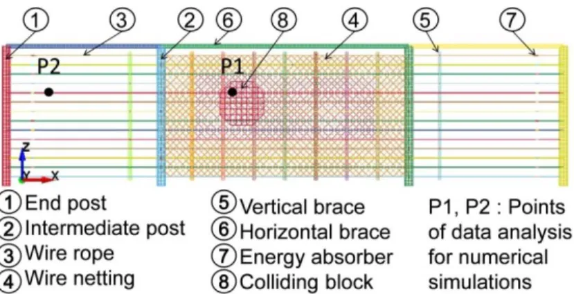
Figure 3.6 Technical sketch of the wire-rope rock fence built in LS-DYNA ... 40
Figure 3.7 A series of motions in Model No.1 ... 41
Figure 3.8 Damage to wire ropes No. 6 and No. 7 and wire netting ... 41
Figure 3.9 Time vs. Y-displacement of center of impact area in Model No. 1 ... 41
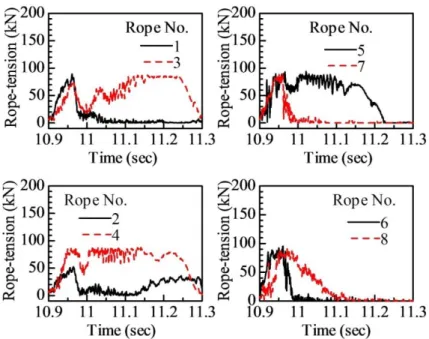
Figure 3.10 Time vs. Rope tension at impact section in Model No. 1 ... 42
Figure 3.11 Time vs. Rope tension at section adjacent to an end post in Model No.1 ... 43
Figure 3.12 Time vs. Rope tension at section adjacent to an end post in Test No.1 . 44 Figure 3.13 Time vs. Block movement in Z-direction in Model No. 2 ... 44
Figure 3.14 Y-displacement history of wire-mesh measured at center of contact area in Model No. 2 ... 44
Figure 3.15 Composite picture from animation in Model No. 2 ... 45
vi
Figure 3.16 Time vs. Rope tension at impact section in Model No. 2 ... 45
Figure 3.17 Time vs. Rope tension at section adjacent to an end post in Model No.2 ... 46
Figure 3.18 Time vs. Rope tension at section adjacent to an end post in Test No.2 . 46 Figure 3.19 Impact force of block in Model No.2 and Test No.2 ... 47
Figure 3.20 Rope tension of rope No.5 for corresponding friction coefficients ... 48
Figure 3.21 Composite picture from animation of intermediate post directly hit ... 50
Figure 3.22 Composite picture in Model No. 2 under E (1000 kJ) and (16 rad./s) 51 Figure 3.23 Composite picture in Model No. 2 under E (1000 kJ) and (18 rad./s) 51 Figure 3.24 Map of impact locations (unit: mm) ... 52
Figure 4.1 Schematic drawing of the developed prototype (unit: mm) ... 57
Figure 4.2 Energy absorbing device ... 59
Figure 4.3 Simplification assumption of energy absorbers ... 60
Figure 4.4 Technical sketch of the developed prototype built in LS-DYNA ... 61
Figure 4.5 Map of impacts on the middle module (unit: mm) ... 62
Figure 4.6 Numerical time histories of fence elongation for impacts at points A and D ... 62
Figure 4.7 Numerical time histories of the deformation of the top of the internal post for impacts at points A and D ... 63
Figure 4.8 Numerical time histories of tension force of rope No. 5 for impacts at points A and D ... 63
Figure 4.9 Impact energy absorbed by wire ropes and wire netting: a) impact at point A; b) impact at point D ... 64
Figure 4.10 Numerical time histories of the block velocity in the Y direction for impacts at points A and D ... 65
Figure 4.11 Map of impacts on the side module (unit: mm) ... 68
Figure 4.12 Numerical time histories of fence elongation for impacts at points H and I ... 68
Figure 4.13 Numerical histories of deformation of the top of the end post for impacts at points H and I ... 69
Figure 4.14 Numerical histories of the base moment of the end post for impacts at
points H and I ... 69
vii
Figure 4.15 Impact energy absorbed by wire ropes and wire netting: a) impact at point H; b) impact at point I ... 70 Figure 4.16 Numerical time histories of the block velocity in the Y direction for
impacts at points H and I. ... 70 Figure 4.17 Breaking of the end post for an impact at point H of the side module with
energy of 800 kJ ... 72 Figure 4.18 Relationship between the AFF of energy absorbers and fence elongation ... 72 Figure 4.19 Animation of the impact at point A of the middle module with the same
energy of 950 kJ but different AFFs: a) AFF of 45 kN ; b) AFF of 60 kN ... 73 Figure 4.20 Animation of the impact at point E of the middle module at impact
energies of 450 kJ (a) and 750 kJ (b) ... 74 Figure 4.21 Technical sketch of the model of two fence units erected side by side .. 74 Figure 4.22 Numerical histories of the fence elongation in cases 1 and 2 ... 76 Figure 4.23 Numerical histories of the connecting post deformation in the X direction
in cases 1 and 2 ... 76 Figure 4.24 Strain rate: a) Wire ropes and b) Posts ... 77 Figure 4.25 Effects of strain rate to the fence response in terms of post deformation
and fence elongation ... 77
Figure 4.26 Fence response to strain rate in term of absorbed impact energy ... 78
viii
List of Tables
Table 1.1 Causes of 308 rockfalls on highways in California ... 3
Table 1.2 Triggering factors of slope failures in Yosemite National Park ... 4
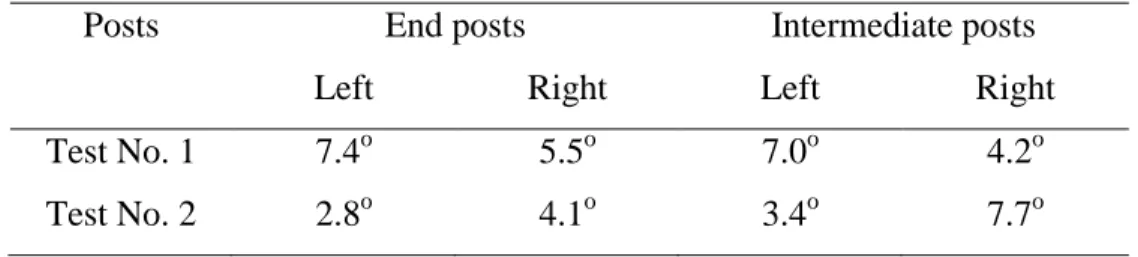
Table 2.1 Deformation data for the posts in the two tests ... 28
Table 2.2 Velocity and impact energy ... 30
Table 3.1 Numerical data of Model No. 1 ... 39
Table 3.2 Automatic contact definitions for Model No. 1 ... 39
Table 3.3 Critical rotation velocity for typical impact energy levels ... 52
Table 3.4 Energy absorption capacity of the rock fence according to six different points of impact ... 53
Table 4.1 Numerical results for fence capacity at different impact locations (points A–F of the middle module) and various block sizes. Le: maximum size D of block; Critical E: highest kinetic energy of a block that can be stopped by the fence. ... 66
Table 4.2 Numerical results of the fence resistance for different impact locations of the side module and block size ... 71
Table 4.3 Energy absorption capacity of a fence composed of two units of the
developed prototype. ... 75
1
Chapter 1 Introduction
1.1 General Background - Literature Review
1.1.1 Rockfall Phenomenon: Definition and Types of Rockfall
Rockfall is a rapid and rather spontaneous natural hazard that often occurs on steep slope, in which rock groups, or single rock blocks detached from the slope face fall down and maybe strike underlying infrastructures. This hazard often im- pacts to small region but its consequences are extremely severe, particularly to humanity. Rockfall differs from landslides by being distinctly extreme surface- phenomena; solid rock; regularly very small in volume; and mostly comprising of singular rather than massed units (Ladd 1935). And Ladd also subdivided rock- fall into four types as follow: 1) Dribble of material; 2) Persistent fall of coarse material (often combined with fine), leading, in nature, to talus accumulations; 3) Falls of loosened rock from jointed or blast-shattered faces of cuts; and 4) Fall of single boulders, or a group of them, often of huge size, and sometimes from a great height (and long horizontal distance), loosened from rock outcrops or cliff faces by undermining as a result of weathering, rain, and seepage wash.
Another more encompassing definition of rockfall was proposed by Cruden and Varnes (Cruden et al., 1996), by which rockfall was defined as a very rapid to extremely speedy slope movement in which bedrock material is detached from a steep slope and descends the slope by falling, bouncing, or rolling. And Ritchie suggested the relationship between slope angle and the type of falling motion of rock blocks (Ritchie 1963). When the slope angle is more than 76
o(or 0.25:1), even the slight accelerative motion of rock blocks at their source can initiate a free fall. With the lesser steep slope, the falling rock hits the slope face and bounces, and when the slope angle is less than 45
o, rolling motions dominate.
Furthermore, relating to the rockfall volume, Rochet classified rockfall phenom- ena into four categories (Rochet 1987):
-
Single block falls, which typically involve volumes ranging between 0.01 and
100 m
3.
2
-
Mass falls, which typically involve volumes ranging between 100 and 100,000 m
3-
Very large mass falls, which typically involve volumes ranging between 100,000 and 10 million m
3.
-
Mass displacements, which typically involve volumes greater than 10 million m
3In general, rockfall hazard is recognized as a complex function of rock blocks of mass, velocity, rotation and jump height, strongly depend on slope characterization and rockfall mechanics (Broili 1973; Bozzolo et al., 1988;
Azzoni et al., 1995)
1.1.2 Rockfall Causes
Rockfall is often triggered by a combination of internal and external causes. In- ternal causes can be the rock mass properties such as bedrock material type, discontinuity pattern, face topography, and ground water. External causes are triggering conditions that change the forces acting on a rock (Pantelidis 2009).
They may be rainfall, snowmelt, seepage, channeled water runoff, weathering, erosion, freeze-thaw and heating-cooling cycles, tree roots, wind, disturbance by animals, and earthquakes. Additionally, human activities such as construction practices, blasting, vibration from equipment and trains, and stress relief due to excavation may be considered as external factors (Hoek 2007). Rockfall are often triggered by these external causes accompanied with rock mass instability.
McCauley surveyed 308 rockfall incidents along California highways and 14
causes of rockfall and their percentage of total were identified and displayed in
Table 1 (McCauley et al., 1985). The table points out that causes related to the
presence of water such as rainfall, freeze-thaw cycles, snowmelt, channeled run-
off, and springs and seeps were totally counted for 67%. Rockfall records for a
19-year period on a major railroad in western Canada showed that approximately
70% of the events happened during the fall, winter, and spring with heavy rainfall,
prolonged periods of freezing temperatures, and daily freeze-thaw cycles (Wyllie
et al., 1996). Peckover did a statistic that rockfalls were most frequent on railway
lines in the Fraser Canyon, British Columbia, Canada, between October and
March, the wettest and coldest time of the year for the area (Peckover 1975).
3
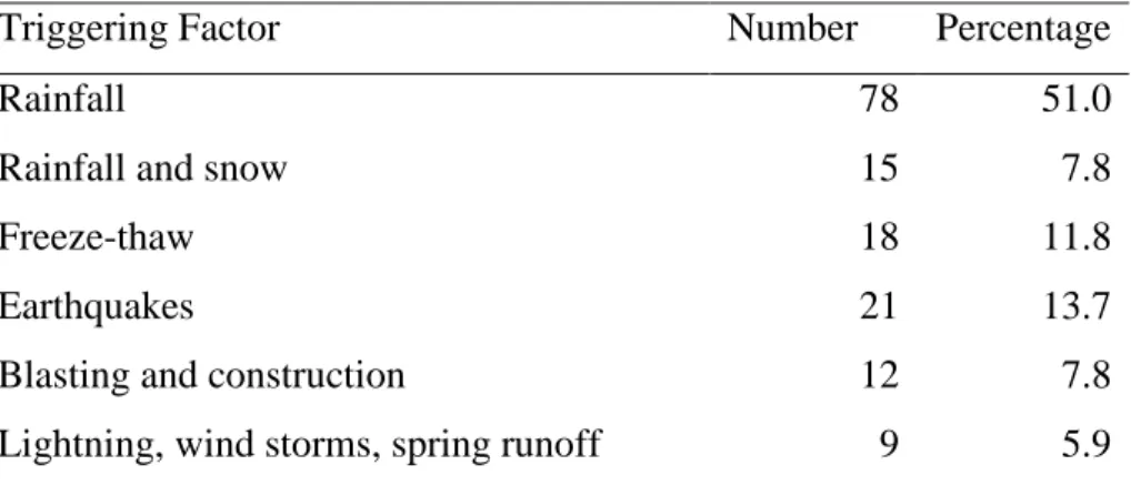
153 slope failure events in Yosemite National Park were examined and triggering factors to each event are displayed in Table 2 (Guzzetti et al., 2003), in which 55% is counted for rockslides and 30% for rockfalls. Among triggering factors, water-related factors (rainfall, rainfall and snow, and freeze-thaw) took 73% of the failures and 14% was attributed to earthquakes.
Generally, there are many causes of rockfall, most of them relate to environmen- tal factors. Particularly, the causes related to water are the most dominant factors triggering the rockfall events. And it is noted that rockfall only occurs as being triggered by combination of internal and external causes.
Table 1.1 Causes of 308 rockfalls on highways in California Causes of Rockfall Percentage of Total
Rain 30
Freeze-thaw 21
Fractured rock 12
Wind 12
Snowmelt 8
Channeled runoff 7
Adverse planar fracture 5
Burrowing animals 2
Differential erosion 1
Tree roots 0.6
Springs or seeps 0.6
Wild animals 0.3
Truck vibrations 0.3
Soil decomposition 0.3
4
Table 1.2 Triggering factors of slope failures in Yosemite National Park
Triggering Factor Number Percentage
Rainfall 78 51.0
Rainfall and snow 15 7.8
Freeze-thaw 18 11.8
Earthquakes 21 13.7
Blasting and construction 12 7.8
Lightning, wind storms, spring runoff 9 5.9
1.1.3 Setbacks of Rockfall Hazards
Compared to other disasters, rockfall usually affects only small region. However, the damage to the infrastructures, particularly transportations, or humanity may be highly serious with probable fatal consequences. Spang reported that rockfalls were the major cause of interruption to the West German Federal Railway’s 28,000 km track network (Spang 1987). Martin concluded that rockfalls, small rockslides, and raveling are the most frequent slope stability problems along transportation routes in mountainous area of North America, annually required tens of millions of dollars on maintenance and protection measures to protect against such hazards (Martin 1988). Sasaki reported that Japan with 70% of mountains has suffered many slope disasters every year with several hundred lives lost (Sasaki et al., 2002)
Specifically, in 1977, large rockfall blocks closed Colorado State Highway 133
near Redstone, Colorado, for several days, pending their breakup by blasting and
removal of material (Turner et al., 2012). On Monday, March 8, 2010, impacts of
large rockfall blocks caused severe damage to the bridge deck located just west
of Hanging Lake Tunnel in Interstate 70 in Glenwood Canyon, Colorado. Inter-
state was closed from early Monday morning until Thursday afternoon while
blocks were broken up by blasting and removed and while unstable residual rock
block on slope was removed. Traffic lanes were restricted for extended period
before bridge deck was repaired (Turner et al., 2012). Kariya reported a rockfall
event in the Daisekkei Valley of Mount Shirouma-dake (1932 m), the northern
5
Japanese Alps that produced debris of
8000 m3, caused casualties of trekkers(Kariya et al., 2005). And Burlington Northern Santa Fe Railway train was hit by rockfall debris near Libby, Montana, on June 25, 2010. Sixteen cars derailed.
Line was reopened one day later after emergency-response crews removed more than 5,400 m3 of debris from track (Turner et al., 2012).
1.1.4 Rockfall Basic Knowledge
Apparently, rockfalls are really considerable threat to lives, equipment, facilities, and transportation corridors in mountainous areas. Therefore, it is crucial to have the best protection based on rigorous hazard and risk management systems and a good understanding of the rockfall behavior as basic knowledge is necessary.
They are site characters, rockfall mechanics, and rockfall trajectories.
The site characters include terrain characteristics, geological and geotechnical
properties of earth materials, rock mass structure, groundwater conditions, and
past and present geological processes. Investigation findings of site characteriza-
tion enable develop a four-dimensional conceptual model, in which three spatial
dimensions are combined with time as the fourth dimension to analyze the inter-
actions of slope properties and processes (Turner et al., 2012). The conceptual
model provides the basis to access the occurrence probabilities of rockfall hazard
as well as analyze rockfall behavior, and ultimately helps determine proper miti-
gation procedures. If slope covers a limited area, conceptual geological model
may be developed by reconnaissance study and forecast of rockfall behavior from
back analysis of past events or by empirical methods. Other cases of slopes of
large areas with frequent rockfall events, more detailed geological information,
and slope topography are often required. Therefore, an extensive investigation of
fieldwork and mapping and, probably, drilling to reach subsurface information
are needed. There were many researches relating to this issue to identify the rock-
fall source zones, to determine the relatively susceptible geological materials in
source zones to rockfall initiation, and to identify as well as describe the rockfall
trajectories and run-out zones (Mazzoccola et al., 2000; Dorren 2003; Guzzetti et
al., 2003; Coe et al., 2005)
6
Evaluation of rockfall mechanics is also required to deeply understand rockfall behavior. Mechanics of rock block movement are usually classified into four types: free falling, bouncing, rolling, and sliding. Among these types, bouncing and rolling that often appear after a falling block hit slope face are the most un- knowable part of a rockfall travel path. Bouncing is typically described in a simplified approach using one or two coefficients of restitution (Wu 1985; Hungr et al., 1988; Pfeiffer et al., 1989; Azzoni et al., 1995). The free-fall trajectory is a parabola (Ritchie 1963). However, a rockfall movement may be any combination of above mechanics.
Rockfall prediction and modeling are often carried out to determine probable tra- jectories of rockfall blocks, their maximum run-out distance, and enabling estimate kinetic energy of the block. This information is really useful for the de- sign of remedial measures of retaining fences and barriers, ditches and berms, or even rock sheds and tunnels. In addition, rockfall prediction and modeling, espe- cially in combination with rock mass stability studies, become important components of hazard assessments for land use planning purpose, particularly in the populated mountainous regions (Turner et al., 2012). A typical serious work- flow of a rockfall trajectory study at the scale of a community or a single slope can be divided into 6 phases: 1) preparation phase; 2) definition of the release scenarios; 3) rockfall modeling and simulation; 4) plausibility check/validation of the model results; 5) fixation of the model results; and 6) transformation into readable rockfall process maps (Lambert S. & Nicot F., 2011). So far available rockfall trajectory simulation models can be classified into 3 groups according to their spatial dimension: 1) two-dimensional (2-D) trajectory models; 2) 2.5-D or quasi-3-D trajectory models; and 3) 3-D trajectory models (Volkwein et al., 2011).
Over the past 30-year period, several 2-D rockfall simulation codes have been developed to anticipate rock block movements and significantly increase the knowledge and understanding of rockfall, allowing to specify relevant rockfall mitigation procedures (Cundall 1971; Cundall et al., 1979; Chen et al., 1999).
The Colorado School of Mines supported by the Colorado Department of Trans-
portation (DOT) as part of the rockfall hazard assessment efforts long the
7
Glenwood Canyon section developed the Colorado Rockfall Simulation Program (CRSP 1.0) in 1988-1989 to model rockfall behavior and provide statistical anal- ysis of probable rockfall events at a given site (Pfeiffer et al., 1989; Pfeiffer et al., 1990). With the support of appropriate computer capacity, the newest version of CRSP extended in 3-D, termed CRSP-3D, was successfully developed to accu- rately model the motions of variably shaped rock block as they travel across slopes. However, whether a rockfall trajectory model is 2-D or 3-D, the experi- ence in applying the model and knowledge of its sensitivity to parameter setting, as well as how to determine model parameter values in the field, is a prerequisite to obtain acceptable results (Volkwein et al., 2011)
1.1.5 Rockfall Mitigation
After properly obtaining basis information of rockfall probably happening on a specific slope, determination of a relevant mitigation measure is recognized as the most important step in hazard and risk management, i.e. a chosen corrective mitigation measure makes previous steps more meaningful.
In a corrective mitigation measure, the proper evaluation should focuses on mul- tiple aspects of continuous maintenance, hazard lessening, and hazard removal.
In addition, particular attention should be paid to the relationship between the annual maintenance costs and the reduction in the costs of potential consequences.
For this reason, rockfall mitigation measures have been classified into two main groups: engineered and non-engineered. Engineered measures including three main categories of stabilization, protection, and avoidance are active interven- tions that diminish the occurrence of effects of rockfalls, while non-engineered measures are more passive interventions that include continued or increased maintenance, warning signs, and slope-monitoring systems (Turner et al., 2012) Stabilization measures include changes in the slope to reduce occurrence proba- bilities of a rockfall. This can be done securing rocks in place, proactively removing loose rocks in a manageable manner, or improving the slope configura- tion to prevent rockfall internal causes from coming to triggering factors.
Stabilization of rock slopes has been well documented in several publications
(Fookes et al., 1976; Wyllie 1980; Wyllie et al., 1996; Schuster 1995; Morris et
8
al., 1999). Rock slope stabilization methods can be divided into two categories:
rock reinforcement (Rock Bolting, Dowels, Shotcrete, Buttresses, Cable Lashing, Anchored Mesh, Cable Nets, Drainage) and rock removal (Scaling, Rock Re- moval, Blast Scaling, Trim Blasting, Resloping) (Turner et al., 2012).
Avoidance measures tend to relocate or realign transportations or other facilities away from zones with high probability of rockfall. Avoidance alternatives are often more costly than stabilization and protection alternatives. However, appar- ently they are safer than others. Particularly, avoidance alternatives become special attractive for large slopes with widespread sources of rockfall (Geiger et al., 1991).
Protection methods consisting of catchment areas, rigid barriers, flexible fences, drapery, and rockshed allow to control rockfalls when they initiate. The main goal of these types of approach is to alter the rockfall behavior by absorbing the falling energy or by capturing rockfalls to prevent them from hitting transporta- tions or other vulnerable targets. This kind of method are more passive and warranted in conditions of (1) Rockfall source zones lie beyond the boundaries of the facilities; (2) The extent or nature of the source zone is impractical or exces- sively costly to stabilize; (3) Avoiding the hazard by facility relocation is not practical or excessively costly (Turner et al., 2012).
Barriers, such as embankments, earthen berms and structural walls, perform as rather rigid systems, capturing or deflecting falling rock blocks by their overall structural stiffness or huge mass. While draperies and fences functioning as flex- ible systems, dissipate the falling energy by their huge deformation when impact occur. Generally, protection alternatives are often more cost-effective than stabi- lization and avoidance ones. Simpler construction is required and fewer environmental impacts are warranted. However, they are not the solution of all situation of rockfall hazard.
1.1.6 Flexible Fences
Flexible fences are commonly employed to control or arrest falling rock blocks
with the aim of protecting infrastructure. A flexible rockfall fence often consists
of interceptive net, which directly intercepts falling rocks, and support structures
9
of posts anchored to foundations or to competent bedrock, tieback and lateral ropes, energy absorbing devices, and anchors. The net panel must have been able to provide huge deformation to dissipate the kinetic energy of falling rocks with significant support of accompanied energy absorbers. Compared with rigid barri- ers, flexible fences are often more cost-effective, and simpler in design. For these reasons, this kind of fence has been impressively developed for wide range of impact energy from 10 to 8000 kJ throughout the world.
Fences were initially applied to protection from snow avalanches in Switzerland;
they involved triangular wire rope nets mounted on timber and, later, steel posts (Spang et al., 2001). Accidentally, this kind of fence was found to successfully capture rockfall that occurred during snow-free periods, opening its new applica- tion for rockfall protection since that time. The first known application of a wire rope fence for rockfall was erected in 1958 at Brusio on southern Switzerland for the protection of power transmission lines. The system consisted of individual rectangular nets measuring 3 × 5 m standing 5 m high, tall even by today’s standards (Turner et al., 2012). During the past 50 years rockfall fence design involved a significant progress mainly based on increasingly modern apparatus for testing, innovation of computer science, and practical demand. Flexibility is consistently considered the basis of design; the enhancement only focuses on ma- terials and constitutive components of the system. In modern fences, energy absorption capacity is the focal point of design. The intercept panel has been in- novated using many new type of material from lightweight wire mesh to robust ring nets. In addition, several types of energy dissipation device have devised, leading to remarkable movement in the fence capacity against rockfall.
When a rockfall strike a fence, the impact energy is transferred from impact loca- tion into adjacent system components and immediately dissipated by the huge flexure of the fence panel along with the performance of any friction energy ab- sorbing devices, if incorporated as part of the fence. Commonly it takes the fence 0.5 s to stop the rock block.
The evaluation of the fence performance is often based on the relationship be-
tween impact loading, maintenance, and efficiency (Turner et al., 2012). Impact
loading is simply the kinetic energy that rockfall impact transfers to the fence.
10
Maintenance relates to required repairs from an impact. The effectiveness of the fence in distributing impact load while diminishing damage discloses the fence efficiency that is strongly influenced by impact location. The fence often reaches the peak of efficiency at the center of intercept panel, where fence panels can ful- ly flex. Flexibility lessens the rockfall loads imparted to fence components and generally enhances the overall ability of the system to absorb greater impact en- ergies with less maintenance. Flexibility and energy dissipation decrease as the impacts target toward the more rigid structures located away from the center point. Consequently, the increase of the maintenance cost of the fence system is certainty after hazard.
The advance in system performance and capacity that have been achieved over the past 50 years would not have been possible without extensive testing of fence systems and components, both in laboratory and from full-scale impacts. This is illustrated most impressively by the increase in fence capacities from an initial 50 kJ to about 8,000 kJ during the period, a nearly 100-fold increase in energy- absorption capacity (Spang et al., 2001)
The various individuals and groups from European countries, principally Swit- zerland and Italy, and Japan have conducted many full-scale tests on different kinds of rock fence to verify them and exchange information. Peila conducted field tests using a guide cable drive the weight from top the slope to targeted point on the fence located at slope base (Peila et al., 1998). The weight was load- ed onto a trolley attached to the cable and traveled down slope to strike the fence without rolling and bouncing. In this manner, the impact energy was accurately calculated. Video cameras were used to monitor and record each test. The forces acting on the cables and posts were also measured.
Muraishi and Sano decribed the testing procedure used by the Japanese Railway
Technical Research Institute (Muraishi et al., 1999). Verification of a fence was
performed conducting laboratory-scale static strength tests on individual fence
components as well as full-scale field test on the fence. The full-scale test was
conducted by dropping a stone from crane into a test fence constructed on a steep
slope. The fence plane created angle of 35
0from horizontal so that the angle be-
tween the fence and the rock trajectory was exactly 55
0. With vertical drop test
11
the impact location and kinetic energy of the block can be reproduced identically in each of a series of tests, allowing reduce the number of required test to meet determined goal compared with the number of rock rolling tests conducted on a hill slope.
Baumann made a review of field tests on rock fences in Switzerland (Baumann 2002). There were more than 350 field tests performed in the country from 1988 to 2002, and the testing procedures as well as fence designs consecutively im- proved during the period. A summary of testing on flexible fence against rockfall is presented in (Thommen 2008). Then there were other full-scale tests with sup- port of better measurement methods to obtain more detailed results (Gottardi et al., 2010). So far, based on how the falling block is accelerated, rockfall field tests can be grouped into two main categories: the test blocks are guided along inclined track cable and vertical free-falling.
In efforts to reduce number of costly full-scale tests but able to enable develop- ment of new types of rock fence, numerical simulation approaches have been performed for first entering deeply the responses of rock fences against rockfalls and then for designing or redesigning. Furthermore, numerical simulations allow consider special load cases that cannot be done in field tests (high-speed rockfall, multiple impact locations such as post/rope strike, etc.) as well as the response of the fence to its structural alterations (Fornaro et al., 1990; Nicot et al., 2001;
Sasiharan et al., 2006; Volkwein, 2005; Cazzani et al., 2002). However, it is cru- cial that the numerical results should be validated by experimental results such as cable tension force, fence deformation as well as acceleration and the trajectory of the falling rock before using for design or redesign purposes.
1.2 Objectives and Scope of the Study
The main objective of this study is focus on rockfall protection with particular
attention paid to developing of flexible fences. In this study, a new type of rock
fence is shown to have a remarkable capacity to capture rocks and thereby pre-
vent damage to transportations as well as fatalities. Basically, with regarding self-
standing to make the fence more suitable to be installed along road side where
12
very little space exists, it was designed with an adequate stiffness without lateral guy cables and anchors. This basis makes the fence distinguishable from Europe- an styles.
This type of rock fence was scrutinized in both full-scale experiments and numer- ical simulation. In field tests, it has been the first time a reinforced-concrete (RC) block was actuated to roll down a natural slope and strike the fence erected at slope base without a navigation system. As a result, the effect of composite mo- tion of an RC block (translation and rotation) on the performance of the rock fence will be clear. To support these tests, laboratory pre-tests on such compo- nents as energy absorbing devices and posts were conducted to examine their load-carrying capacities and structural behaviors. In addition, an experimental measure system was devised to control and obtain more detailed results from the tests.
Numerical simulation using the finite element code LS-DYNA reproduced the fence response against impact of the block, enabling to reach a deeper under- standing of the structural non-linear behavior of the fence under severe dynamic condition. The valuable experimental data obtained from full-scale tests helped validate the numerical models in terms of the fence deformation, the block trajec- tory after impact, impact force between the block and the fence, etc. Parametric analysis with iterative execution was then performed to determine the structural function of each individual component of the system and how these components interact with one another during rockfall event. Furthermore, an investigation in- to the effect of the impact location on the resistance of the fence, which could not be done experimentally, was also carried out through a series of numerical mod- els, allow verify the fence resistance under various impact conditions.
Based on gained understanding of this kind of fence, a new prototype is devel-
oped increasing post spacing and reducing the number of wire netting layer with
the aim of reaching appreciable cost benefits. Above validated numerical proce-
dure was employed to clarify the response of the prototype to these structural
alterations before using in practice. Specifically, fence elongation, post defor-
mation, and ultimately the energy absorption capacity of the developed prototype
were thoroughly examined. Particularly, the response of side module (refer to
13
section 4.3.2 for details) of the prototype against rock impacts has been first time examined in the study, producing more detailed understanding about the fence resistance under various impact locations. Furthermore, to improve the fence re- sistance a simple but efficient enhancement method was proposed and scrutinized using iterative numerical models. Last but not least, this study also explored the performance of a fence comprising two units of the developed prototype, which is the most practical application suited to wide protection areas. And despite the numerical procedure specifically targeting the design of this fence, the methodol- ogies and findings derived from this work are likely to be valuable to understanding comparable types of rock fence.
Following are Chapter 2 that presents experiments on a wire-rope rockfall protec- tive fence, Chapter 3 expressing dynamic finite element analysis on the fence, and Chapter 4 set for introduction of a new prototype of the fence developed with three-dimensional numerical modeling.
1.3 References
Cazzani A. ongio L., Frenex T. (2002). Dynamic Finite Element Analysis of Interceptive Devices for Falling Rocks. International Journal of Rock Mechanics and Mining Sciences 39(3): 303–321.
Azzoni A., Barbera G. L., A. Z. (1995). Analysis and Prediction of Rockfalls Using a Mathematical Model. International Journal of Rock Mechanics and Mining Sci- ences 32(7): 709–724.
Azzoni A., & De Freitas M. H. (1995). Experimentally Gained Parameters, Decisive for Rock Fall Analysis. Rock Mechanics and Rock Engineering 28(2): 111–124.
Baumann R. (2002). The Worldwide First Official Approval of Rock-Fall Protection Nets. The 53
rdAnnual Highway Geology Symposium, San Luis Obispo, Calif 40–51.
Bozzolo D., Pamini R., & Hutter K. (1988). Rockfall Analysis - a Mathematical
Model and its Test With Field Data. The 5th International Symposium on Land-
slides, Balkema, Rotterdamm, Lausanne, Switzerland 555–563.
14
Broili L. (1973). In Situ Tests for the Study of Rockfall. Geologia Applicatae Idro- geologia 8:105-111.
Chen G., & Ohnishi Y. (1999). Slope Stability Analysis Using Discontinuous De- formation Analysis. The 37
thU.S. Rock Mechanics Symposium, Rock
Mechanics for Industry (B. Amadei, R. L. Kranz, and G. A. Scott, eds.), Vail, Colo., Balkema, Rotterdam, Nethrelands 535–541.
Coe J. A., Harp E. L., Tarr A. C., & Micheal J. A. (2005). Rock-Fall Hazard As- sessment of Little Mill Campground, American Fork Canyon, Uinta National Forest, Utah. Open-file Report 2005-1229. U.S. Geological Survey, Reston, Va.
Cruden D.M., & Varnes D.J. (1996). Landslide Types and Processes. Special Report 247: Lanslide: Investigation and Mitigation (A.K. Turner and R.L. Schuster, eds.), Transportation Research Board, National Research Council, Washington, D.C. 36–75.
Cundall P. A. (1971). A Computer Model for Simulating Progressive, Large-Scale Movements in Blocky Rock Systems. Symposium on Rock Fracture of the Inter- national Society of Rock Mechanics, Nancy, France, Balkema, Rotterdam, Netherlands 2–8.
Cundall P. A., & Strack O. D. L. (1979). A Discrete Numerical Model for Granular Assemblies. Geotechnique 29: 47–65.
Dorren L. K. A. (2003). A Review of Rockfall Mechanics and Modeling Approach- es. Progress in Physical Geography 27: 69–87.
Fookes P. G., & Sweeney M. (1976). Stabilization and Control of Local Rock Falls and Degrading Rock Slopes. Quarterly Journal of Engineering Geology 9: 37–
55.
Fornaro M., Peila D., & Nebbia M. (1990). Block Falls on Rock Slopes-Application of a Numerical Simulation Programm to some Real Cases. The 6
thInternational Congress IAEG, Rotterdam, Netherlands.
Geiger G., Humphries R. W., & Ingraham P. C. (1991). Design of Repairs to High-
way Rock Slopes along the Ohio River in Ohio. National Symposium on
Highway and Railroad Slope Maintenance, Association of Engineering Geolo-
gists, Denver, Colorado 75–90.
15
Gottardi, G., & Govoni, L. (2010). Full-scale Modelling of Falling Rock Protection Barriers. Rock Mechanics and Rock Engineering 43(3): 261–274.
doi:10.1007/s00603-009-0046-0.
Guzzetti F., Crosta G., Detti R., & Agliardi F. (2003). STONE: A Computer Program for the Three-Dimensional Simulation of Rock Falls. Computers & Geosciences 28(9): 1079–1093.
Guzzetti F., Reichenbach P., & Wieczorek G. F. (2003). Rockfall Hazard and Risk Assessment in the Yosemite Valley, California, USA. Natural Hazards and Earth System Science 3(6): 491–503.
Hoek E. (2007). Practical Rock Engineering. Rocscience Inc., Toronto, Ontario, Canada. Retrieved from http://www.rocscience.com/education/hoeks_corner.
Hungr O., & Evans S. G. (1988). Engineering Evaluation of Fragmental Rockfall Hazards. 5
thInternational Symposium on Landslides (C. Bonnard, ed.), Balkema, Rotterdam, Netherlands 1: 685–690.
Kariya Y., Sato G., Mokudai K., Komori J., Ishii M., Nishii R., Miyazawa Y., Tsumura N. (2007). Rockfall Hazard in the Daisekkei Valley, the Northern Japa- nese Alps, on 11 August 2005. Landslides (4): 91-94.
Ladd G. E. (1935). Landslides, Subsidences and Rockfalls as Problems for the Railroad Engineer. 36
thAnnual Convention of the American Railway Engineer- ing Association 1091–1162.
Lambert S., & Nicot F. (2011). Rockfall Engineering.
Martin D. C. (1988). Rockfall Control: an Update. Bulletin of the Association of Engineering Geologists XXV(1): 137–139.
Mazzoccola D., & Sciesa E. (2000). Implementation and Comparison of Different Methods for Rockfall Hazard Assessment in the Italian Alps. The 4
thCongress of the International Association of Engineering Geologists (E. Bromhead, N. Dix- on, and M. L. Ibsen, eds.)-Landslides in Research, Theory and Practice, New Delhi, India 221–228.
McCauley M. L., Works B. W., & Naramore S. A. (1985). Rockfall Mitigation.
FHWA Report FHWA/CA/TL-85/12. Federal Highway Administration, U.S.
Department of Transportation, Washington, D.C.
16
Morris A. J., & Wood D. F. (1999). Rock Slope Engineering and Management Process on the Canadian Pacific Railway. The 50
thAnnual Highway Geology Sympposium, Roanoke, Va. 264–275.
Muraishi H., & Sano S. (1999). Full-Scale Rockfall Test of Ring Net Barrier and Components. Semonar on Rockfall Tests and Standardization, Davos, Switzer- land.
Nicot, F., Cambou, B., & Mazzoleni, G. (2001). Design of Rockfall Restraining Nets from a Discrete Element Modelling. Rock Mechanics and Rock Engineering 34(2): 99–118. doi:10.1007/s006030170017.
Pantelidis L. (2009). Rock Slope Stability Assessment Throught Rock Mass Classifi- cation Systems. Rock Mechanics and Mining Sciences 46: 315–325.
Peckover F. L. (1975). Treatment of Rock Falls on Railway Lines. American Rail- way Engineering Association Bulletin 653 471–503.
Peila, D., Pelizza, S., & Sassudelli, F. (1998). Evaluation of Behaviour of Rockfall Restraining Nets by Full Scale Tests. Rock Mechanics and Rock Engineering 31(1): 1–24. doi:10.1007/s006030050006.
Pfeiffer T. J, & Bowen T. (1989). Computer Simulation of Rock Falls. Association of Engineering Geologists Bulletin 26(1): 135–146.
Pfeiffer T. J., & Higgins J. D. (1990). Rockfall Hazard Analysi Using the Colorado Rockfall Simulation Program. In Transportation Research Record 1288, Trans- portation Research Board, National Research Council, Washington, D.C. 117–
126.
Ritchie A. M. (1963). Evaluation of Rockfall and Its Control. In Highway Research Record 17, Stability of Rock Slopes, Highway Research Board, National Re- search Council, Washington, D.C. 13–28.
Rochet L. (1987). Application of Numerical Propagation Models to the Study of Rocky Lanslides. Bulletin Liaison des Ponts et Chaussées 150-151, 84–95.
Sasaki Y., Dobrev N., Wakizaka Y. (2002). The Detailed Hazard Map of Road Slopes in Japan. Public Works Research Institute, Japan.
Sasiharan, N., Muhunthan, B., Badger, T., Shu, S., & Carradine, D. (2006). Numeri-
cal analysis of the performance of wire mesh and cable net rockfall protection
17
systems. Engineering Geology 88(1-2): 121–132.
doi:10.1016/j.enggeo.2006.09.005
Schuster R. L. (1995). Recent Advanaces in Slope Stabilization. The 6th Internation- al Symposium on Landslides, Balkema, Rotterdam, Netherlands 3: 1715–1745.
Spang R. M. (1987). Protection against Rockfall Stepchild in the Design of Rock Slopes. 6th International Conference on Rock Mechanics, Montreal, Quebec, Canada, Balkema, Rotterdam, Netherlands 551–557.
Spang R. M., & Bolliger R. (2001). From the Timber Fence to the High Energy Net:
Developments in Rockfall Protection from the Origins to the Present. Geobrugg Jubilee Conference, Bad Ragaz, Switzerland.
Thommen R. A. (2008). Testing of Various Types of Rockfall Flexible Wire Rope Mitigation Barrier: an Overview of Testing to date. The 59th Highway Geology Symposium, Santa Fe.
Turner A. K., & Schuster R. L. (2012). Rockfall Characterization and Control.
Volkwein, A., Schellenberg, K., Labiouse, V., Agliardi, F., Berger, F., Bourrier, F., Dorren, L. K. A., et al. (2011). Rockfall characterisation and structural protection – a review. Natural Hazards and Earth System Science 11(9): 2617–2651.
doi:10.5194/nhess-11-2617-2011.
Volkwein, A. (2005). Numerical Simulation of Flexible Rockfall Protection Systems.
Computing in Civil Engineering 179: 122–122. doi:10.1061/40794(179)122.
Wu S. S. (1985). Rockfall Evaluation by Computer Simulation. Transportation Research Record 10311, Transportation Research Board, National Research Council, Washington, D.C. 1–5.
Wyllie D. C. (1980). Toppling Rock Slope Failures, Examples of Analysis and Stabilization. Rock Mechanics 13: 89–98.
Wyllie D. C., & Norish N. I. (1996). Stabilization of Rock Slopes. In Special Report
247: Landslides: Investigation and Mitigation (A. K. Turner and R. L. Schuster,
eds.), Transportation Research Board, National Research Council, Washington,
D.C. 474–504.
18
Chapter 2 Experiments on a Wire-Rope Rockfall Protective Fence
2.1 Introduction
Many methods of protecting against rockfall have been devised around the world.
They can be classified into prevention and protection types. A prevention method involves the removal or stabilization of dangerous rocks on a slope. A protection method uses interceptive structures such as an embankment, a rock shed or a rock fence to catch rockfall in the middle or at the end of a slope.
An embankment has the advantage of lower construction and repair costs and the capacity to absorb higher rockfall energy than other structures, but it requires a suitable construction site. The embankment approach has been experimentally and numerically analyzed (Ronco et al. 2009; Lambert et al. 2009; Maegawa et al.
2011).
Many rock sheds have been constructed for mountainous roads in Japan. Impact tests have been carried out on a real rock shed to confirm its ultimate capacity (Kishi et al. 2002). However, the design basis for a rock shed in the Rockfall Mit- igation Handbook (Japan Road Association 2006) is allowable stress design and leads to underestimation of the performance–cost ratio of a rock shed compared with the other structures.
The principal advantages of a rock fence are its rapid erection and easy mainte- nance. Some countries such as Japan, Italy, Switzerland, France and the United States have developed many types of rock fence. For instance, different types of fence were tested at a field test site in Europe, and flexible and practicable solu- tions for designing and constructing a rock fence were established as guidelines for the approval of rockfall protection kits (Gerber 2001; ETAG-027 2008). A flexible rock fence made from polyethylene netting, which is resistant against alkalis, acids, water, sudden impact, low temperature, and ultraviolet rays and can withstand high rockfall energy, was developed in Japan (Maegawa 2006).
Rock fences made from netting have the important feature of being able to absorb
19
rockfall energy through their flexibility, which is achieved by large displacement of the cable net and by energy-dissipating devices mounted on the connecting cables.
In this study, a new type of rock fence made of posts, wire ropes, wire netting, and energy absorbers is shown to have a remarkable capacity to catch rocks and thereby prevent damage to vehicles and houses as well as fatalities. Basically, with regarding self-standing and accordance with narrow spaces of the fence, it was designed with an adequate stiffness without lateral guy cables and anchors.
Moreover in Japan, the design scheme for a rock fence is based on a desired en- ergy-absorption capacity (Japan Road Association 2006). To absorb a large amount of energy, the wire rope of the rock fence is semi-fastened to a post using an energy-absorbing device (Maegawa et al. 1995) as shown in Fig. 2.1 in which and following figures the default unit of dimensions is millimeter. When pulled, the wire rope does not slip from the device until the magnitude of the friction force exceeds a critical value, which is possible to vary. As the wire rope slips, the device is able to maintain a fluctuating kinetic frictional force between it and the wire rope until a stopper located at the end of the rope comes into contact with the energy absorber. The wire rope thus does not break and part of the im- pact energy is absorbed by the energy absorber.
Figure 2.1 Absorber -Type A(a) and Absorber-Type B(b)
Two types of energy absorber will be introduced and examined with respect to
their configuration and corresponding energy-dissipation behavior. To reduce the
number of energy absorbers and achieve lower cost while maintaining perfor-
20
mance, energy absorbers were installed only at the end posts of the new type of fence. This type of rock fence was examined in full-scale experiments carried out using a reinforced-concrete (RC) block that rolled down a natural slope without a navigation system. Since an RC block under this experimental condition has not only translational motion but also rotational motion, the composite effect of the natural motion on the performance of the rock fence will be clear. In preparation for these tests, laboratory pre-tests on such components as energy absorbers and posts were conducted to confirm their load-carrying capacities and structural be- haviors. Additionally, an experimental control system was devised to investigate the impact force between the block and fence in the tests.
2.2 Configuration of the Rock Fence
2.2.1 Details of the Rock Fence
Figure 2.2 shows the configuration and dimensions of the rock fence. Four posts made of concrete-filled steel tubes were vertically erected with a rigid joint on a concrete foundation, forming three spans with unequal length of 5, 8, and 5 m.
These unequal dimensions come from the site condition that was just fit for the fence of 18 m long. Fortunately, it is certain that elongation of the 18 m long fence is smaller than that of equal length of 8, 8, and 8 m fence; i.e., likely safer to use the fence of 18 m in this study. Fourteen wire ropes employed as main components to catch rockfall were horizontally installed by connecting to both end posts via energy absorbers that are effective in preventing the wire ropes from breaking. Each wire rope passed a steel-ring welded to intermediate posts.
The extension length of each wire rope from the energy absorber was 800 mm,
and a stopper was attached at the end of each wire rope to prevent the rope from
sliding out of the energy absorber. Additionally, seven vertical braces of steel
plates were installed at mid-span of the fence to help maintain the spacing be-
tween wire ropes. The vertical brace semi-fastened each wire rope by two wire
clips. With the aim of supporting the wire ropes to catch rockfall, two layers of
wire netting comprising 5-mm steel wire having grid spacing of 50 mm were
used. The wire netting and wire rope were connected by several steel-wire coils.
21
To brace the posts against one another in the plane of the fence, the top of each adjacent post was connected to a steel pipe functioning as a horizontal brace.
As shown in Fig. 2.1, two types of energy absorber were used in full-scale tests.
The energy absorber consisted of a U-shaped bolt and two types of steel block.
Each steel block consisted of two steel plates with thicknesses of 25 to 38 mm.
The two steel plates were stacked one upon the other and the concave indenta- tions of the two plates held in place a wire rope when they were compressed together by two M20 bolts at 200 Nm/bolt. The critical friction force between wire rope and the steel plates depends on the torque of the M20 bolts. Further- more, as shown in Fig. 2.1a and b, the two types of energy absorber differ in the interval between the two steel blocks. In the Type-B energy absorber, the smaller steel block can initially slide along the U-bolt a distance of 60 mm, until contact- ing the larger one fixed to the U-bolt. In contrast, in the Type-A energy absorber, there is no interval between the two steel blocks and both of them are fixed to the U-bolt. This difference affects the timing of the maximum rope tension during rockfall collision.
Figure 2.2 Configuration and dimensions of the rock fence (unit: mm)
22 2.2.2 Experimental Control System
Figure 2.3 Experimental control system
Figure 2.3 shows the experimental control system mainly aimed at measuring the rope tension and the acceleration of the RC block. To record the acceleration data of the RC block at a sampling rate of 2 kHz, a three-axis accelerometer, analog- to-digital transformation recorder, and transceiver were placed at the center of the RC block. The transceiver acted to start up the recorder as soon as it received the trigger signal emitted from the master transceiver. Next, another analog-to-digital transformation recorder was synchronized to accumulate the data at a sampling rate of 2 kHz from strain gauges attached to the U-bolts of the energy absorbers.
These data helped in estimating the wire-rope tension because the relation be-
tween the strain of the U-bolt and the tension force of the wire rope has been
measured in a laboratory test. Additionally, a high-speed camera (600
frames/second) was set up on the side of the fence to capture the instant that the
RC block makes impacts with the fence. Since the camera's starting frame was
also synchronized, the frame number at the time of collision helped to specify the
collision time in the acceleration history data. The RC block velocities were es-
timated from a series of frames shortly before the RC block strikes the fence. The
prominent feature of this measurement system is that the accumulated data are
synchronized by means of transceivers. Moreover, several other high-speed cam-
23
eras (300 frames/second) were set up at the most appropriate positions to monitor the interaction between the RC block and rock fence.
2.3 Outline of the Experiments
2.3.1 Pre-testing and Results for Energy Absorbers
Two types of energy absorber were tested in the laboratory to examine their be- havior, in particular the friction force between the energy absorber and wire rope.
Figure 2.4 describes the configuration and procedures of the laboratory test for an energy absorber. One end of the wire rope was connected to the test frame through a load cell, and the opposite part was held by an energy absorber; i.e., steel blocks. The outer wire rope from an energy absorber was free and was the extension for the sliding function. The remainder of the wire rope could be set at a length of about 5 m for the test, since the curved end of the U-bolt was con- nected to the test frame. The test procedure was as follows. A 1340-kg weight freely dropped along vertical guides and struck the middle of the wire rope, and the extension of the wire rope then slid through the energy absorber. The rope tension was measured using a load cell, and the rope slippage was calculated from the weight displacement measured using a rotary encoder connected to the weight. Additionally, the relation between the strain of each U-bolt used in the rock fence and the rope tension was examined in tensile tests under a static load.
This relation was used to estimate the rope tension from the U-bolt’s strain data recorded for the fence subjected to an impact load.
Figure 2.5 shows the results for the impulsive friction force for the two types of
energy absorber. Independent of the device type, the impulsive friction force
fluctuated widely, indicating that the wire rope exhibited alternate behaviors of
slipping and stopping. However, the fluctuation of the Type-B energy absorber
began at a lower friction force than that of the Type-A energy absorber. This dif-
ference certainly derives from the interval between the two steel blocks of the
Type-B energy absorber, since the friction force initially occurred only in the
larger steel block owing to this interval as mentioned in Section 2.2.1. No wire
ropes broke during testing, and Fig. 2.6 shows that the maximum instantaneous
friction forces for the Type-A and Type-B energy absorbers were 157 and 150
24
kN, respectively and they were less than the nominal strength of the wire rope (180 kN). Additionally, the average values of the impulsive friction force, ob- tained by dividing the final potential energy of the weight by the total slippage of the wire rope, were 65.2 and 45.4 kN for Type-A and Type-B energy absorbers, respectively.
Figure 2.4 Laboratory test for an energy absorber (unit: mm)
Figure 2.5 Impulsive friction vs. rope elongation curve
25
Figure 2.6 Test diagram
2.3.2 Test of the Rock Fence
Two tests were carried out. The sole difference between the tests is that Type-A and Type-B energy absorbers were applied in Tests No. 1 and No. 2, respectively.
The mass of the weight and its falling height were identical in the two tests. After Test No. 1, all components other than the posts were replaced with new ones.
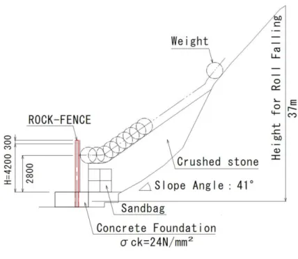
The shape of the RC block was in accordance with the EOTA guidelines for fall-
ing-rock protection kits (ETAG-027 2008), as shown in Fig. 2.3. The RC block
was covered with 6-mm-thick steel plates and weighed 5.2 tons. In the tests, the
block began rolling from the peak of a slope at a height of approximately 37 m
and then stuck the fence, which was located at the bottom of the slope, as shown
in Fig. 2.6.
26
2.4 Results of Rock Fence Tests
2.4.1 Behavior of the Rock Fence
Figure 2.7 Collision point on the rock fence at mid-span
Figure 2.7 shows the collision point marked by an octagon at the mid-span of each fence. The collision point in Test No. 1 was slightly left of center. The tar- get was set at a height of 2.7 m from the concrete foundation.
Figures 2.8 and 2.9 show the impact process; i.e., the motion of the RC block and the behavior of the rock fence just before and during the collision in Test No. 1 and Test No. 2, respectively, and the peak elongation of the wire netting. These images generally indicate that the fence could decelerate and captured the RC block in both tests. However, more thorough examination of the overall behavior of the fence shows differences between the two tests.
Figure 2.8 Behavior of the rock fence (Test No. 1)
27
Figure 2.9 Behavior of the rock fence (Test No. 2)
Relating to the deformation of the fence, the peak elongation of the wire mesh in Test No. 2 was slightly larger than that in Test No. 1. Another discrepancy be- tween two tests pertains to rope breaking. In Test No. 1, rope breaking was observed (wire ropes No. 1 through No. 7 broke, as shown in Fig. 2.7) and this is because the rope tension is not constant. It is higher in the impact region. In par- ticular there was no slippage between the wire ropes and energy absorbers in Test No.1. In contrast, there was slipping in Test No.2 as illustrated in Fig. 2.10, ena- bling the fence to stop the RC block without the breaking of wire ropes.
After each test, theodolites were used to measure post deformation expressed by a post’s declination in units of degrees in different directions with reference to the vertical. Site observations showed that the end posts only inclined in the fence plane and intermediate posts only inclined in a vertical plane perpendicular to the fence plane. Table 2.1 showing the declination data of the posts, shows that the deformation of the end posts in Test No. 1 was greater than that in Test No. 2, again demonstrating the great efficiency of the Type-B energy absorbers. Addi- tionally, within each test, the collision location logically affects the difference in deformation between right and left posts.
Furthermore, the deformation of vertical braces in the Y-direction perpendicular
to the fence plane, particularly the vertical braces in the impact region, generally
reflecting the residual shape of the fence for both tests was measured. The maxi-
mum residual deformation in both tests is less than 1.1 m.
28