JAIST Repository
https://dspace.jaist.ac.jp/
Title エクサスケールコンピューティングのためのエネルギ
ー効率を考慮した新しい階層型相互結合網
Author(s) Faisal, Faiz Al Citation
Issue Date 2018‑09
Type Thesis or Dissertation Text version ETD
URL http://hdl.handle.net/10119/15533 Rights
Description Supervisor:井口 寧, 情報科学研究科, 博士
A New Hierarchical Interconnection Network with considering Efficient Energy Usage for Exa-scale
Supercomputing
By Faiz Al Faisal
A thesis submitted to School of Information Science,
Japan Advanced Institute of Science and Technology, in partial fulfillment of the requirements
for the degree of
Doctorate of Information Science
Postgraduate Program in Information Science
Written under the direction of Professor Yasushi Inoguchi
September, 2018
Copyright c2018 by Faiz Al Faisal
Abstract
The requirement of high processing power is enormous; one of the high desire of next gen- eration HPC systems. Since every computer chip has limited processing power, sequential processors can’t be the suitable choice. For example, an Intel Core i7-3630QM processor (4 cores, 22nm fabrication process) can achieve about 76.8GFlops through the requirement of 45W electrical power usage. However, the requirement for exa-scale computing will require about 13 million of connecting such processors. Todays most powerful supercom- puter Sunway Taihulight System has already achieved about 93 petaFlops performance with 10,649,600 cores requiring about 15.3MW electrical power using low degree 2DMesh interconnect (2DMesh has the performance constraints and faster saturation rate). More- over, a high degree network like- Tofu (6DMesh/Torus) interconnect used in K-computer has achieved 10.51 petaFlops performance (88,128 SPARC64 VIIIfx processors, Tofu in- terconnect with 10 cores to cores connectivity) by requiring 12.6MW of electrical power.
Hence, to build an exa-flops Tofu system, it will require near about 1260MW of electri- cal power with the current advancements. These observations confirm that conventional structures are not feasible for the next generation networks due to the high power usage for the high degree core to core connectivity (Tofu interconnect) and also shows poor network performances (2DMesh interconnect). Hence, the possible solution to reach the next generation exa-scale performance is to redesign the ”Interconnection Network”.
Exa-scale supercomputing requires network scalability over millions of cores and the performance constraint affects heavily for the large system along with the total power us- age. In considering those constraints our focus resides on the ”Hierarchical Interconnection Networks (HIN)”. HINs possess the features like- constant node degree, small average dis- tance, better bisection width, small number of wires and low network latency with high throughput. Constant node degree ensures the fixed router cost throughout the entire system, small average distance eliminates the possibility of the performance degradation, better bisection width ensures the network traffic handling capability, wiring complexity is effective for reducing the network power usage and finally, network latency ensures the packet reachability with the requested traffic load. This research also considers a new parameter of ”Network Energy Usage” to ensure the high performance and the low power usage. Moreover, we have considered two possible network configuration of 65K cores and 1M cores analysis to ensure the superiority of our network for the exa-scale system.
Keywords: Interconnection Network, Hierarchical Flattened Butterfly Network, Esti- mation of Power Consumption, Dynamic Communication Performance, Energy Usage.
Contents
Abstract 1
1 Introduction 8
1.1 Introduction . . . 8
1.2 Problem Statement . . . 9
1.3 Objective of this Research . . . 10
1.4 Contribution of the Dissertation . . . 12
1.5 Organisation of the Thesis . . . 13
2 Related Works on Conventional and Hierarchical Interconnections 15 2.1 Introduction . . . 15
2.2 General Terminology . . . 16
2.3 Related Works . . . 17
2.4 Conventional Networks with Mesh and Torus Interconnect . . . 17
2.5 Hierarchical Interconnection Networks (HIN) . . . 20
2.5.1 Tori-connected mESH (TESH) Network . . . 20
2.5.2 Tori-connected Torus Network (TTN) . . . 20
2.5.3 Rectangular Twisted Torus Meshes (RTTM) . . . 22
2.5.4 Midimew Connected Mesh Network (MMN) . . . 22
2.6 Tofu Network . . . 24
2.7 Requirements for Exa-scale Computing . . . 24
2.8 Summary . . . 25
3 Network Design of HFBN 26 3.1 Introduction . . . 26
3.2 Theoretical Design of HFBN . . . 26
3.2.1 Physical Aspects of Different Network Layers . . . 26
3.2.2 Design Consideration and Analysis for On-chip and Off-chip Network 27 3.2.3 Definition of Hierarchical Flattened Butterfly Network (HFBN) . . 30
3.2.3.1 Discussion of Size of the HFBN Basic Module(BM) . . . . 35
3.2.3.2 Discussion of Size of the Upper-level HFBN . . . 36
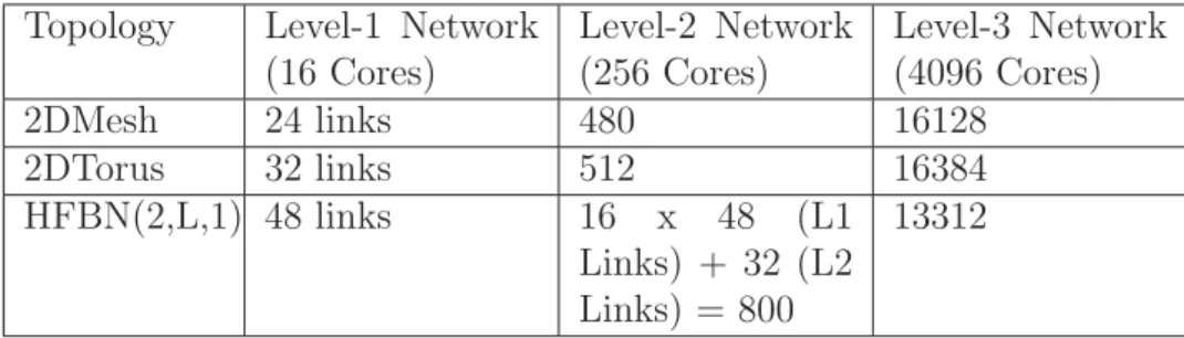
3.2.4 Number of Links at Various Network Levels . . . 39
3.2.5 Routing Algorithm for HFBN . . . 40
3.2.6 Deadlock-free Routing for HFBN . . . 42
3.3 Self Evaluation on HFBN . . . 43
3.3.1 Optimal Configuration of HFBN for m, L and q . . . 43
3.3.2 Evaluation on Deadlock-freeness . . . 51
3.4 Summary . . . 52
4 Efficient Energy Usage 53 4.1 Introduction . . . 53
4.2 Evaluation on Efficient Energy Usage . . . 53
4.3 Dynamic Communication Performance . . . 55
4.3.1 Definition of Various Traffic Patterns . . . 55
4.3.2 Evaluation on Dynamic Communication Performance . . . 56
4.4 Estimation of Power Consumption . . . 56
4.4.1 Assumption for the Power Model . . . 57
4.4.2 Electrical Power Model . . . 57
4.5 Efficient Energy Usage Analysis (1M Cores) . . . 58
4.5.1 Uniform Traffic . . . 59
4.5.2 Perfect Shuffle Traffic . . . 60
4.5.3 Bit-compliment Traffic . . . 62
4.6 Efficient Energy Usage Analysis (65K Cores) . . . 63
4.6.1 Uniform Traffic . . . 65
4.6.2 Perfect Shuffle Traffic . . . 66
4.6.3 Bit-compliment Traffic . . . 68
4.7 Summary . . . 69
5 Conclusion 70 5.1 Conclusion . . . 70
5.2 Future Research . . . 71
Publications 77 Appendix A 78 5.2.1 Diameter Performance . . . 85
5.2.2 Average Distance . . . 87
Appendix B 92
Appendix C 95
Acknowledgments 118
List of Figures
1.1 Existing network topology for system shares [3] . . . 9
1.2 Performance Consideration in Latency and throughput . . . 12
2.1 Network structure of 2DMesh Network . . . 18
2.2 Architecture of 3DTorus Network . . . 18
2.3 Wiring cost analysis on the conventional networks . . . 19
2.4 Static Power analysis on the conventional networks . . . 20
2.5 Basic Module of TESH Network [21] . . . 21
2.6 Basic Module of TTN Network [23] . . . 21
2.7 Architecture of RTTM Network [22] . . . 22
2.8 Basic Module of MMN . . . 23
2.9 Level-2 Network Connectivity for MMN . . . 23
2.10 Network Connectivity for Tofu [1] . . . 24
3.1 Block diagram for Blue Gene/L supercomputer [29] . . . 27
3.2 On-chip Energy Consumption . . . 29
3.3 Off-chip Energy Usage (static analysis) . . . 29
3.4 Interconnection of HFBN . . . 30
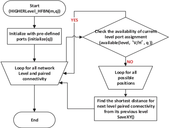
3.5 Flowchart for Port Assignment Algorithm . . . 35
3.6 A (4×4) Basic Module of HFBN . . . 36
3.7 Higher-level of Interconnection for HFBN(2, L, q) . . . 38
3.8 Increased paired connectivity for each level . . . 39
3.9 Routing Path for HFBN(2,3,1) . . . 41
3.10 Analysis on NEU of HFBN for m, L, q(16M Cores) . . . 46
3.11 Analysis on Uniform Traffic of HFBN for m, L, q(16M Cores) . . . 46
3.12 Analysis on NEU of HFBN for m, L, q(1M Cores) . . . 48
3.13 Analysis on Uniform Traffic of HFBN for m, L, q(1M Cores) . . . 48
3.14 Analysis on NEU of HFBN for m, L, q(65K Cores) . . . 50
3.15 Analysis with Uniform traffic of HFBN for m, L, q(65K Cores) . . . 50
3.16 Uniform Traffic Analysis for Deadlock-freeness . . . 52
4.1 Energy Usage with uniform traffic (1M Cores) . . . 59
4.2 Energy Usage with Perfect Shuffle traffic (1M Cores) . . . 61
4.3 Energy Usage with Bit-compliment Traffic (1M Cores) . . . 62
4.4 Energy Usage with uniform traffic (65K Cores) . . . 65
4.5 Energy Usage with Perfect Shuffle Traffic (65K Cores) . . . 67
4.6 Energy Usage with Bit-compliment Traffic (65K Cores) . . . 68
A.1 Uniform Traffic Analysis with Various Network Size of HFBN . . . 81
A.2 Various networks with uniform traffic (1M Cores) . . . 81
A.3 Various networks with Perfect Shuffle traffic (1M Cores) . . . 82
A.4 Bit-compliment Traffic Analysis for various networks (1M cores) . . . 82
A.5 Various networks with uniform traffic (65K Cores) . . . 83
A.6 Various networks with Perfect Shuffle Traffic (65K Cores) . . . 83
A.7 Various networks with Bit-compliment Traffic (65K Cores) . . . 84
A.8 Diameter Performance for Various Networks . . . 86
A.9 Average Distance for Various Networks . . . 87
A.10 Cost analysis for Various Networks . . . 88
A.11 Packing density for Various Networks . . . 89
A.12 Message Traffic density for Various Networks . . . 90
A.13 On-chip connectivity for Various Networks . . . 91
A.14 CEF for Various Networks . . . 91
A.15 TCEF for Various Networks . . . 92
B.1 Results of Orion 2.0 [33] . . . 94
B.2 Verification for Orion 2.0 . . . 94
B.3 Verification for DCP Simulator [53] . . . 95
B.4 Verification for DCP analysis on Mesh and Torus network . . . 95
List of Tables
1.1 petaFlops/megawatt analysis for supercomputers . . . 11
2.1 Commercially used networks in MPC systems . . . 16
2.2 Total number off-chip interconnect with 4K Cores . . . 19
3.1 Evaluated static performance for various networks . . . 28
3.2 Simulation Condition for On-chip Energy consumption . . . 28
3.3 Generalisation of HFBN . . . 37
3.4 Possible number of cores with various levels of HFBN . . . 38
3.5 Generalisation of number of links at various levels of HFBN . . . 40
3.6 Example of required number of links at various levels of networks . . . 40
3.7 Simulation Environment for Traffic Analysis (16M cores) . . . 45
3.8 Consideration for Power Usage . . . 45
3.9 Uniform Traffic Energy Analysis(16M cores) . . . 47
3.10 Simulation Environment for Traffic Analysis (1M cores) . . . 47
3.11 Uniform Traffic Energy Analysis(1M cores) . . . 49
3.12 Simulation Environment for Traffic Analysis (65K cores) . . . 49
3.13 Uniform Traffic Energy Analysis(65K Cores) . . . 51
3.14 Simulation enviornment for HFBN . . . 52
4.1 Static NEU Evaluation . . . 55
4.2 Simulation Environment for Traffic Analysis . . . 58
4.3 Simulation Environment for Inter-chip Model (electrical interconnect) . . . 58
4.4 Consideration for optical interconnect . . . 59
4.5 Uniform Traffic Energy Analysis(1M Cores) . . . 60
4.6 Perfect Shuffle Traffic Energy Analysis(1M Cores) . . . 61
4.7 Bit-compliment Traffic Energy Analysis(1M Cores) . . . 63
4.8 Simulation Environment for Traffic Analysis . . . 64
4.9 Simulation Environment for Inter-chip Model (electrical interconnect) . . . 64
4.10 Consideration for optical interconnect . . . 64
4.11 Uniform Traffic Energy Analysis(65K Cores) . . . 66
4.12 Perfect Shuffle Traffic Energy Analysis(65K Cores) . . . 67
4.13 Energy Analysis of Bit-compliment Traffic(65K Cores) . . . 69
A.1 Simulation Environment for Traffic Analysis . . . 79
A.2 Simulation Environment for Traffic Analysis (1M Cores) . . . 80
A.3 Simulation Environment for Traffic Analysis(65K Cores) . . . 80
A.4 Static Simulation Enviornment . . . 84
A.5 Node Degree of Various Networks . . . 85
A.6 Calculated Formulation of Diameter for HFBN . . . 86
B.1 Simulation Condition for Power Analysis . . . 93
Chapter 1 Introduction
1.1 Introduction
Exa-scale performance is the next goal post for next generation supercomputers and most likely next generation high performance computing is solely depends on the massively parallel computers. Modern massively parallel computer (MPC) systems like- K-computer has already achieved 10.51 petaFlops performance with more than 80,000 computing cores and also requires about 12.6MW electrical power [1]. In addition, to achieve the exa-scale performance the scaling will be required about 95 times and required power consumption will be close to 1200MW for K-computer. On the other hand, Blue Gene/Q supercomputer requires 6.6MW of electrical power in achieving 20 petaFlops performance with 1.57M processor core. However, this supercomputer will require about 330MW of electrical power for building the exa-scale system. Therefore, the reduction of the power usage of the MPC systems is the one of the important issues for the next generation exa-scale supercomputers along with continuing the other constraints like- low network performance, poor scalability, poor throughput and large network latency [2].
The overall performances as well as the power consumption of MPC systems are heavily affected by the interconnection networks and its processing cores. Interconnection network acts as a communicating path for processing cores and as well as for the memory units. The main goal of this research is to find a suitable hierarchical interconnection network that will be suitable for the exa-scale processing. As the processing power of the single CPU core is limited, it is important to integrate a large number of processing cores to enhance the performance of the massively parallel system. Titan, which already achieved 17.59 petaFlops speeds using about 560,640 processor cores, including 261,632 NVDIA K20x accelerator cores. Hence, to achieve the exa-scale computing we need to find a suitable interconnection network that have high scalability with shorter global interconnect for the low power usages. Consequently, every MPC system requires interconnection network as an obvious choice. Figure 1 shows the latest scenario of existing interconnects for MPC systems, according to system shares [3]. This figure confirms that the vastly used network is the Tree network for the MPC systems, which was used in early days and also it has has a big concern in case of network performance and even most of the modern
3.4%
5.8%
6.8%
84%
Tree
3D Torus
5D Torus
Dragonfly
Figure 1.1: Existing network topology for system shares [3]
supercomputers are build upon the conventional Mesh and Torus topology (for example- one of the top supercomputer, Sunway TaihuLight uses the 2DMesh network as their network interconnect [4]). In MPC systems, the total number of outgoing links like- on- chip as well as off-chip links is a big concern, due to power usages as well as high latency.
However, Friedman shows 3D NoC requires less power usage than the 2D NoCs with shorter vertical links [5]. Hence, the interconnect pattern for network topology is a vital issue for the next generation exa-scale supercomputers.
On the other hand, efficient energy usage means delivering the same outcome while using less energy. Todays most of the power planets produces the electrical power through burning coal, fuel and gas. And burning them results in the conversion of carbon to carbon dioxide (CO2), which is then released into the atmosphere. The estimated CO2 emission from burning fossil fuel is about 10 billion tonnes yearly. This results in an increase in the earths level of atmospheric CO2, which enhances the greenhouse effect and contributes to global warming. On the other hand, the amount of heat generated from the electronic devices is equivalent to the power input. For example- a heatsink rated at 100C/W will get 100C hotter than the surrounding air when it dissipates 1 Watt of heat. Hence, the reduction in energy usage ensures the reduction of impacts on the environment and even low power usages ensures the less failure rate for the devices.
1.2 Problem Statement
Networks are the only way for the processors to be interconnected in a MPC system.
High degree networks (4D, 5D) ensure maximum performance through a large number of core-core interconnections. However, high radix or node degree introduces heavy power usage. Hence, the problem for next generation MPCs will be the maximum performance through low power usage which leads to the efficient network. On the other hand, 3D NoCs are one of the attractive feature for the exa-scale systems for the low power usages (decrease 62%) than the 2D NoCs [5]. However, 3D NoCs have not been available in the
market due to the high fault tolerant issues of through-silicon via (TSV) links and its massive heat generation. Even today’s modern supercomputers have also been classified with green list [6]. Table 1.1 shows the recent green listed supercomputers, where the recent MPC systems as Gyoukou ensures the maximum petaFlops/megawatt efficiency of 14.14 (about 42.88% better than the Piz Diant).
On the other hand, exa-scale system is the only desire for the next generation super- computing. However, exa-scale system can be achieved through interconnecting millions of cores. For example- China’s Sunway TaihuLight supercomputer uses 40,960 64-bit RISC processors, containing 256 processing cores for each processor and an additional four auxiliary cores for system control for a total of 10,649,600 CPU cores for the entire system. Sunway system achieved about 93 petaFlops linkpack performance. However, integrating a large number of CPU cores requires huge power usages as well as the net- work latency trends to get saturated very soon. Sunway system requires about 15MW of electrical power to run the full system and considers the 2DMesh network for the core Networks are the only way for the processors to be interconnected in a MPC system.
High degree networks (4D, 5D) ensure maximum performance through a large number of core-core interconnections. However, high radix or node degree introduces heavy power usage. Hence, the problem for next generation MPCs will be the maximum performance through low power usage which leads to the efficient network. On the other hand, 3D NoCs are one of the attractive feature for the exa-scale systems for the low power usages (decrease 62%) than the 2D NoCs [5]. However, 3D NoCs have not been available in the market due to the high fault tolerant issues of through-silicon via (TSV) links and its massive heat generation. Even today’s modern supercomputers have also been classified with green list [6]. Table 1.1 shows the recent green listed supercomputers, where the recent MPC systems as Gyoukou ensures the maximum petaFlops/megawatt efficiency of 14.14 (about 42.88% better than the Piz Diant).
On the other hand, exa-scale system is the only desire for the next generation super- computing. However, exa-scale system can be achieved through interconnecting millions of cores. For example- China’s Sunway TaihuLight supercomputer uses 40,960 64-bit RISC processors, containing 256 processing cores for each processor and an additional four auxiliary cores for system control for a total of 10,649,600 CPU cores for the entire system. Sunway system achieved about 93 petaFlops linkpack performance. However, integrating a large number of CPU cores requires huge power usages as well as the net- work latency trends to get saturated very soon. Sunway system requires about 15MW of electrical power to run the full system and considers the 2DMesh network for the core interconnectivity.
1.3 Objective of this Research
The main target of this research is to find the suitable interconnect for next genera- tion exa-scale supercomputers. The initial target for the next generation interconnection networks is to provide sufficient bandwidth. Bandwidth is a considerable factor for the running applications. Hence, network latency should remain considerable as long as ap-
Table 1.1: petaFlops/megawatt analysis for supercomputers MPC system Country Performance
(petaFlops)
Power(MW) petaFlops/MW
Sunway Taihulight China 93.0 15.4 6.04
Tianhe-2 China 33.9 17.8 1.91
Piz Daint Switzerland 19.6 2.27 8.63
Gyoukou Japan 19.1 1.35 14.14
plication bandwidth requirement is much smaller than the bandwidth, which is available through the network. Figure 1.2(a) shows the relation between the delivered bandwidth (offered load) vs. latency, where networks get saturated after a certain amount of deliv- ered bandwidth. On the other hand, figure 1.2(b) shows the relation between delivered bandwidth (throughput) vs. offered bandwidth, where network ensures the maximum amount of traffic the network can handle before it get saturated. Therefore, the initial task of an interconnection network is to transfer the data from the source to destinations with the requirements of following targets:
1. Low average transfer time (low latency) 2. High transfer rate (high throughput) 3. Low system cost
One of the most powerful modern supercomputer on earth Sunway TaihuLight System has already achieved about 93 petaFlops performance with 10,649,600 cores requiring about 15.3MW electrical power with the 2DMesh interconnect. The consideration for the 2DMesh network is his constant and low number of out-going links from each core.
However, the saturation rate for Mesh network is very fast and even the zero load latency is high. On the other hand, 2D Torus could be an alternative for this latency improve- ment with increased number of virtual channels, which ensures the less zero load latency than the Mesh networks. However, the increased number of virtual channels induces the increase in power usage due to the activity at the channel buffer. Hence, our designed network considers those observations to reduce the number of virtual channels at the on- chip level and even shows the better zero load latency and high saturation rate than the conventional networks.
Chip Multiprocessors (CMPs) mostly adopt conventional interconnects like- Mesh and Torus, which consume an increasing fraction of the chip power. Moreover, as the technol- ogy advances and voltage continues to scale down, static power consumes a large fraction of the total power. Hence, reducing the total power usage is increasingly important for energy proportional computing. Efficient energy usage ensures the reduced amount of energy required to provide the suitable performance. For example- power usage effec- tiveness (PUE) of the Swiss Supercomputer (CSCS) datacenter prior to 2012 was 1.8, however the current PUE is about 1.25; a factor of 1.5 improvements [7]. With the mod- ern advancements, the biggest concern for supercomputers is the power dissipation. The
(a) Network Latency (b) Network Throughput
Figure 1.2: Performance Consideration in Latency and throughput
most powerful supercomputer on earth Sunway TaihuLight System has achieved about 93 petaFlops performance with 10,649,600 cores requiring about 15.3 MW electrical power installed with 2DMesh network, which will require 168.3 MW of electrical power for the exa-scale performance (close to 1 nuclear power plant) [4].
In consideration for performance and power usage, we like to introduce our new param- eter, which is network energy usage. Network energy is defined by the average transfer time for transmitting the flits from the source core to destination cores (which is also called as the network latency) multiplying with the required network total power usage (this power usage leads by the power requirement from the routers and the connected links). Equation 1.1 shows this assumption condition. On the other hand, the efficiency of energy usage is the reduction of the obtained network energy usage in comparing be- tween two networks with the relative request-probability (r). In dynamic communication performance analysis, packets are transmitted by the request-probability (r) during the simulation clock cycles. This value is calculated in percentage. The lower the network energy usage the better the efficiency can be obtained. As the modern MPCs are highly affected by the power consumptions, efficient energy usage can able to trace the system performance with respect to power usage, which is an absolutely new feature in the field of interconnection networks.
Network Energy Usage (NEU) = Average Transfer Time×Network Total Power Usage (1.1)
1.4 Contribution of the Dissertation
Energy consumption completely dominated by costs of data movement. The most critical problem for 3D networks is the massive heat generation. On the other hand, it is obvious
that 3D networks require a much higher number of off-chip connection than the 2D net- works (50% higher). Even the cost and the power usage for 3D networks is much higher than 2D networks. This consideration leads to 2D NoC architecture is obvious choice for the exa-scale supercomputing. Even the Sunway supercomputer used the 2DMesh network for considering the exa-scale system. However, hierarchical networks are prefer- able over the conventional networks due to the hierarchical design for the modern MPC systems. Hence, in this research, we are considering a 2D NoC based hierarchical network for the interconnect for next generation exa-scale system.
Packet routing for interconnection networks plays the most crucial role to transmit the messages from one core to another. Bad routing logic can degrade the network perfor- mance. On the other hand, dimension-order routing (DOR) has been the most popular for MPC systems due to its minimal hardware requirements and allows the router configura- tion to simple and cost-effective. The performance of the networks can be found through the dynamic communication performance. Dynamic communication performance can be obtained from the latency and throughput analysis. However, a deadlock-free routing is an obvious choice for any interconnection networks. Our network has also considered a deadlock-free DOR routing for the traffic analysis.
Now, our next phase of research will be evaluating the power usage of the new net- work. In on-chip level the power consumption of the interconnection network depends on the total router power usages and summation of per link power usages. Even total power consumption highly depends not only on the leakage power, but also the dynamic power of both routers and link modules. On the other hand, the off-chip connection mainly draws the power usage from the leakage power. Hence, our estimation for power usages will require the evaluation of on-chip and off-chip power consumption for various interconnection networks with common parameters. On the other hand, power usage for interconnection network does not reflect the performance analysis. Hence, a network, which shows low power usage with little low performance, has always been neglected due to the poor performance though it could be handy for next generation computers. To sort out this issue, we like to ensure the efficient energy usage for the various interconnects.
Finally, it is being expected from the interconnection network with low cost, low degree, low congestion, high connectivity, high packing density and high fault tolerance. Along with those static parameters, cost-effectiveness factor and also time-cost-effectiveness fac- tor have also been used to evaluate the system cost and system performance of the MPC systems. As the network topology affects the performance metrics, it is important to mea- sure the static network performance for the new interconnection network with comparing against the various networks.
1.5 Organisation of the Thesis
The chapter 1, introduces the requirements for exa-scale supercomputing and their con- straints for achieving such requirements. And, now, we would like to ensure the synopsis of the rest of the dissertation as follows:
1. In chapter 2, we considers with most challenging comparators for our network.
Hence, chapter 2 includes the basic architecture of the conventional networks as well as the hierarchical networks. Hierarchical networks treated as the low diameter, low average distance and low cost requirements over the conventional networks. In addition, we shows the requirement of exa-scale supercomputing for the generation HPCs.
2. In chapter 3, we like to introduce our designed network. Our designed network is based on the heterogeneous architecture, which means it flows different architecture at the different network level. In our case, we have considered the 2D flattened butterfly network at the on-chip level and 2DTorus network at the off-chip level or the upper level of network with the certain network configuration.
3. Chapter 4 presents the evaluation of energy usage for various networks. Combining the power usage and the dynamic performance, we obtained the efficient energy usage for our designed network. Those analyses are considered with variable network size like- 65K cores and 1M cores. With the large network size, HINs can show better network performance as well as the low network energy usage.
4. Finally, chapter 5 concludes the thesis with the future work and we have considered the static network performance for our designed network in appendix A, which also ensures the superiority of our designed network over the other networks. Appendix B shows the verification of various simulators that are used in this research. And finally, Appendix C shows the sample code for obtaining the network analysis.
Chapter 2
Related Works on Conventional and Hierarchical Interconnections
2.1 Introduction
Network topology is the most important choice for the MPC systems, where network topology refers as the static arrangement of channels and cores in an interconnection network. Channels are used to transmit the packets over the whole network. In addition, routing strategy and flow-control method heavily relies over the network topology. Hence, selecting the preferable network is the first choice for the MPC system. On the other hand, network power is also affected by the router radix.
Interconnection networks allow the send and receive of packets in the MPC systems over the interconnected cores. Hence, the research on interconnection networks has been quite wide, ranging from simple bus network to complex heterogenous networks. Some of them are designed with the graph property only and never been implemented in real MPC systems. Moreover, interconnection networks are classified with the direct and indirect interconnect. Direct networks maintains point to point connectivity with different cores according to the network topology. However, indirect networks don’t follow the point to point connectivity; rather it connects any two core through the some switches. Multistage interconnection networks are the classic example of the indirect networks [18]. In this dissertation, we have considered only the direct networks.
Direct network topologies are defined by the graph theories. Hence, each node in graph theory is presented as the single processing element in MPC systems. However, we refined the nodes as the core, which is the individual processing element resides in each processor. On the other hand, edges are referred as the link between the cores.
Graph theory also ensures the symmetry or asymmetry nature of the graph. In case of networks, it can be symmetric if it confirms its isomorphism to itself with any core.
Symmetric network ensures substantial advantages over the asymmetric networks. The most important feature is the network scalability. Symmetric networks allow to expand in a modular fashion. Then, it ensures the use of simple routing algorithm, which is also effective for the message passing parallel programs.
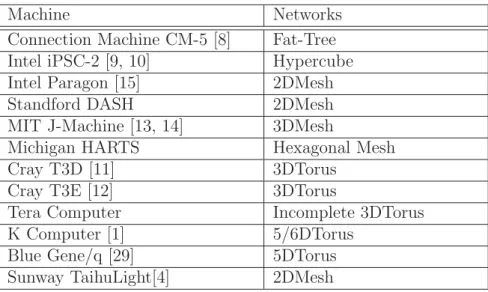
Table 2.1: Commercially used networks in MPC systems
Machine Networks
Connection Machine CM-5 [8] Fat-Tree Intel iPSC-2 [9, 10] Hypercube
Intel Paragon [15] 2DMesh
Standford DASH 2DMesh
MIT J-Machine [13, 14] 3DMesh
Michigan HARTS Hexagonal Mesh
Cray T3D [11] 3DTorus
Cray T3E [12] 3DTorus
Tera Computer Incomplete 3DTorus
K Computer [1] 5/6DTorus
Blue Gene/q [29] 5DTorus
Sunway TaihuLight[4] 2DMesh
The modern interconnection networks of the MPC systems mainly focus on the fixed router radix because it is very important to maintain fixed router cost with the increased scalability. Increased router radix has the performance efficiency but also increases the router cost and also the power usages for the increased link connectivity and router activity. On the other hand, a constant router radix network allows to construct very large networks from the lowest network module. This regularity and modularity ensures that direct networks are often considered for the MPC systems. Table 2.1 shows the several topologies that are considered for various MPC systems.
2.2 General Terminology
Interconnection network helps to interconnect the processors as well as the memory mod- ules. This section defines the basic terminology for the interconnection network and we also follows those terminology throughout the thesis.
Interconnection Network: Interconnection network acts as a graph where each ver- tices are defined as single computational unit and edges are defined as the communication links.
Core: A core acts as an individual computational unit in a massively parallel computer system. It consists of computational unit, local memory, supporting devices and a router.
Communication Link: A communication link acts as a data transmission path for one core to another. Communication links can be unidirectional or bidirectional.
Buffers: Buffers helps to hold the data before the packet could be delivered to the network. Hence, every communication channel in each core requires certain number of buffers to hold the packet.
2.3 Related Works
Networks are the backbone of a MPC system. MPC system heavily depends on the inter- connected channels for communicating with other CPU cores or its memory system. How- ever, earlier research on the interconnection networks was considered only conventional structures, which caused the degradation of network performance as well as the increased off-chip power usage. Furthermore, power estimation in CMOS VLSI chip shows that off-chip driven power can be scaled up to 65% of the total power consumption [16]. In addition, Infiniband QDR 40Gbps switch requires typically about 1W of electrical power for per link. Hence, the power consumptions have been heavily affected with increased off-chip connections. On the other hand, the most important feature for hierarchical inter- connection networks (HIN) is the ability to maintain variable link structure for different network levels, which leads to the reduced off-chip power. Reduction in the power usage of the MPC systems considers three possibilities- (1) millivolt switch, (2) memory in 3-D and (3) specialized network architecture. Hence, our consideration for reducing the power usage is based on the network architecture. 16-tile MIT RAW on-chip network requires 36% of the total chip power [46]. In addition, in an Alpha 21364 microprocessor, the integrated routers and links consume about 20% of the total chip power (about 25W of total chip power 125W) (a 128 core 2Dtorus network fabricated with 180nm fabrication process) [28]. To achieve the exa-scale performance, one of the most challenging prob- lems for the modern supercomputers is the reduction of current power consumptions. In addition, the requirement of power usages can be even scaled up to more than 300MW (which is nearly equal to the one nuclear power plant) with the conventional networks [17]. On the other hand, high degree networks show much better performance than the low degree of networks. However, high degree networks require higher power usage for their high degree of interconnected links.
2.4 Conventional Networks with Mesh and Torus In- terconnect
Mesh [19] is one of the k-ary n-cube networks, which is very well-known for field of inter- connection network and easy to layout in on-chips as well as for the off-chip connectivity.
2DMesh has been used in Sunway supercomputer with the achieved performance of 93 petaFlops. Average latency of Mesh network is O(sqrt(N)) with O(N) cost. Mesh net- work requires lowest number of virtual channels for the deadlock-freeness. However, it can’t ensure the suitable network communication performance with the large network size.
Figure 2.1 shows the network structure for 2DMesh network.
Torus also resides as another k-ary n-cube network [20]. However, Torus network con- siders extra wraparound links over the Mesh network. Hence, Torus requires 2 VC for its deadlock-free. Modern supercomputer like- Blue Gene/Q considers 5DTorus network as the interconnecting module with the achieved performance of 17 petaFlops performance included with the 18 core on-chip. Figure 2.2 shows the network architecture for 3DTorus.
Figure 2.1: Network structure of 2DMesh Network
Figure 2.2: Architecture of 3DTorus Network
Table 2.2: Total number off-chip interconnect with 4K Cores
# Inter-chip links # Intra-rack links
2DMesh 1536 384
2DTorus 1536 512
3DMesh 3840 1152
3DTorus 4864 1280
4DMesh 3840 4224
4DTorus 4864 5376
System cost of MPC systems is highly correlated with increased number of wiring in- terconnect. High degree conventional networks require high number of wiring complexity, which increases the system performance and also increases the system cost. For ex- ample, the Modern super-computers like- Blue Gene/Q considered high degree network (5DTorus) for its own interconnect. However, the latest top ranked supercomputer Sun- way Taihulight with 93 petaFlops performance considered the 2DMesh network to reduce the total system cost. Figure 2.3 shows system cost with respect to chip-chip links (level-2 links) and intra-rack links (level-3 links) (Figure 2.3(a) is the cost for the 4096 cores and Figure 2.3(b) is the scaled cost for 1M cores). We considered the electrical links at the inter-chip level and optical links at the intra-rack level. The consideration for number of links are shown at Table 2.2. This analysis explains that 2DMesh network will require about 90.39% less amount of cost for designing level-2 and level-3 off-chip links than the 4DTorus network. On the other hand, figure 2.4 shows the power usages at the inter-chip and intra-rack links.
2DM 2DT 3DM 3DT 4DM 4DT 0.0
50.0k 100.0k 150.0k 200.0k
Total Cost ($)
Various Topologies (4096 Nodes) Intra-rack level (10.76 (fiber) + 17.98(GBIC))
Inter-chip level (1.4x + 2.16)
(a) Cost Analysis with 4K Cores
2DM 2DT 3DM 3DT 4DM 4DT 0
10M 20M 30M 40M 50M
Total Cost ($)
Various Topologies (1M Nodes) Intra-rack level (10.76 + 17.98)
Inter-chip level (1.4x + 2.16)
(b) Cost Analysis with 1M Cores Figure 2.3: Wiring cost analysis on the conventional networks
2DM 2DT 3DM 3DT 4DM 4DT 0
4000 8000 12000 16000
TotalPower(w)
Various Topologies (4096 Nodes) Intra-rack level (0.0101 (optical) + 1.2x(GBIC Module))
Inter-chip level (0.0135)
(a) Power Analysis with 4K Cores
2DM 2DT 3DM 3DT 4DM 4DT 0.0
500.0k 1.0M 1.5M 2.0M 2.5M 3.0M 3.5M 4.0M
TotalPower(w)
Various Topologies (1M Nodes) Intra-rack level (0.0101 (optical) + 1.2x(GBIC Module))
Inter-chip level (0.0135 (electrical))
(b) Power Analysis with 1M Cores Figure 2.4: Static Power analysis on the conventional networks
2.5 Hierarchical Interconnection Networks (HIN)
2.5.1 Tori-connected mESH (TESH) Network
The Tori-connected mESH (TESH) [21] network was introduced by V.K. Jain, et al.,is a hierarchical interconnection network. TESH consists of multiple basic modules (BM) that are hierarchically interconnected for building large scale system. The BM size of the TESH network is defined as (2m×2m), where BM is the Level-1 network. On the other hand, higher level networks are interconnected as 2DTorus fashion. A TESH(m,L,q) can have number of cores at each level as N = 22mL; where m is any positive integer, L is network level and q is node interconnectivity. if m = 2, the size of the BM is (4×4). A BM of TESH (4×4) is shown in Figure 2.5.
2.5.2 Tori-connected Torus Network (TTN)
Tori connected Torus Network (TTN) [23, 24] was introduced by M.M. Hafizur Rahman, et al., considers the Torus connection over the Mesh connection. In the level-1 network or basic module level TTN considered the 2DTorus network and even at the off-chip level, it also considered the 2DTorus network. A (2m×2m) on-chip module consists of a 2DTorus network of 22m processing elements (PE) and m is a positive integer. Figure 2.6 shows the on-chip module for TTN with m = 2, which defines the size of BM as (4×4). TTN requires 4 virtual channel for its deadlock-free routing.
Figure 2.5: Basic Module of TESH Network [21]
Figure 2.6: Basic Module of TTN Network [23]
2.5.3 Rectangular Twisted Torus Meshes (RTTM)
Rectangular Twisted Torus Meshes (RTTM) are similar to TESH network, which was pro- posed in 2010 [22]. This network also considers reducing the network diameter through the Mesh network at the on-chip level with (2m×2m) cores. However, the interconnection at the off-chip level is quite different than the TESH network, considers recursively inter- connected ax2a next lower level sub-networks in the form of a rectangular twisted torus.
This network has also high scalability with up to a millions of processors. Figure 2.7 shows the network interconnection for RTTM. RTTM ensures much better performance than the TESH network and also have the features of smaller diameter, shorter average distance and higher average link utilisation.
Figure 2.7: Architecture of RTTM Network [22]
2.5.4 Midimew Connected Mesh Network (MMN)
Midimew connected Mesh Network (MMN) considered the 2DMesh networks as the lowest level network, similar to TESH network, which was proposed in 2014 [25]. This network also considers reducing the network diameter through the Mesh network at the on-chip level with (2m×2m) cores. However, the interconnection at the off-chip level is midimew, considers different node connectivity for the off-chip level than the TESH network and RTTM network. This network has also high scalability with up to a million of processors.
Figure 2.8 shows the basic module for MMN. A MMN(m,L,q) is also a hierarchical inter- connection networks, where m is a positive integer, L is used for the network level and q is used for the inter-level connectivity. Upper level networks are connected with 22m im- mediate lower level of sub-networks considering (2m×2m) MInimal DIstance MEsh with Wraparound links (midimew) network. Figure 2.9 shows the level-2 network connectivity for the MMN.
Figure 2.8: Basic Module of MMN
Figure 2.9: Level-2 Network Connectivity for MMN
2.6 Tofu Network
Tofu is a highly scalable network consists of 6D mesh/torus connectivity. Tofu(X,Y,Z,A,B,C) network considers XYZ connection for the intra-rack level and/or for the inter-rack con- nectivity. On the other hand, Tofu(X,Y,Z,A,B,C) considers ABC connection for the intra-chip level. Tofu network consists of 10 out going link. Hence, the node degree for Tofu(X,Y,Z,A,B,C) is 10. Each adjacent pair of ABC mesh/torus is interconnected with 12 links. Tofu considers extended dimension order routing and also requires 2 VC for deadlock-freeness [63]. Figure 2.10 shows the Tofu(X,Y,Z,A,B,C) network level intercon- nectivity. The on-chip module for Tofu consists of 12 cores. In this thesis (as comparing the network models of node level and the rack level), we have considered the 240 cores for the node level (similar to 256 cores of other networks), in total of 4080 cores at the each rack level for Tofu network. We have considered the Tofu(40,32,68,3,2,2) network with 1,044,480 cores as the 1M cores energy evaluation and the Tofu(20,16,17,3,2,2) network with 65,280 cores as the 65K cores energy evaluation.
Figure 2.10: Network Connectivity for Tofu [1]
2.7 Requirements for Exa-scale Computing
Exa-scale computing related to the ’ExaFlops system’. One exaFlops (EFLOPS) system will be capable of performing about one quintillion (1018) floating-point operations per sec- ond. This computational power is so large that any single human will require to perform one calculation in every second for 31,688,765,000 years to be the equivalence of a single second computational power of exa-scale computer and in the next generation computing requires this massive scale to improve the scientific fields (such as- ’Reducing Pollution’- can be possible through exa-scale computing, it will be possible to redesign the combustion systems in engines and increase the efficiency by 25-50%, ’Weather Prediction’- modern supercomputers are still lagging behind to make the proper weather forecasting due to the lack of computer performance, ’New Energy Solutions’- redesigning of wind turbines
along with the solar panels will be an essential choice for the next decade). Modern super- computers like- Sunway TaihuLight has already achieved about 93 petaFlops (PFLOPS) performance with 10,649,600 CPU cores. This constitutes that massive number of core scalability is required to meet this excessive demand. Most of the modern networks have poor scalability and even considers high router radix for meeting the high performance demand. Moreover, the high router radix increases the system cost as well as the power usage for the communicational links and routers (due to increase of processing activity in the local buffers) [36, 37].
2.8 Summary
This chapter we have introduced the general terminology for this thesis. The area of interconnection networks is quite wide. However, energy efficient supercomputing is a very new scope for this research. This chapter defines some useful comparators for energy efficient computing and we would maintain those comparator networks throughout the thesis. This chapter also explains the requirement for exa-scale supercomputing. More- over, it also explains the reasons of avoiding the high degree networks for using in the large scale system.
Chapter 3
Network Design of HFBN
3.1 Introduction
The interconnection network plays the role to interconnect the multiprocessors and its memory module [1]. Hence, the performance of high performance computing (HPC) sys- tems are likely depends on the network design. Since every computer chip has limited processing power, sequential processors cant be the suitable choice. However, the require- ment for exa-scale computing will require about 13 million of connecting such processors.
Hence, the requirement of interconnecting network has a huge impact for building exa- scale systems. Furthermore, todays one of the most powerful supercomputer Sunway Taihulight System has already achieved about 93 petaFlops performance with 10,649,600 cores requiring about 15.3MW electrical power using 2D Mesh interconnect [4]. The main concern for exa-scale systems are the reduction of power usage; for example- Sunway sys- tem will require about 168.3MW electrical power in achieving the exa-scale system with the modern advancements [4]. On the other hand, the network with high saturation rate will be obviously a poor consideration for the exa-scale system along with the network power usage is also another big concern as our target to build an exa-scale system within 20MW [27]. For example, in Alpha 21364 microprocessor, the network routers and links consume about 20% of the total chip power usage (25W of total chip power 125W) using 128 core 2DTorus network fabricated with 180nm process [28]. Furthermore, Off-chip links requires long interconnecting distance, causing much higher off-chip power than on-chip.
3.2 Theoretical Design of HFBN
3.2.1 Physical Aspects of Different Network Layers
Modern supercomputers are designed with various levels of hierarchy. For example- on- chip level as the lowest level network and off-chip level as the upper level network. Hence, the number of cores have the limited numbers at the on-chip level. For example- Blue Gene/Q chip was designed with 18 cores 64-bit A2 processor and 16 of those processor cores are used for computing with 5DTorus network having 2GB/s chip-to-chip links
Figure 3.1: Block diagram for Blue Gene/L supercomputer [29]
[29]. However, those link cost is cheap, requires about pico-J power and aggregated bandwidth can be about 10GB/s. Figure 3.1 shows the design consideration for Blue Gene/L generation. Now, if we consider the network at an off-chip level, where next upper-level over the on-chip level is the node level. Node level considers multiple on-chip module to be interconnected, which can be connected through the Peripheral Component Interconnect Express (PCI express) [29]. Hence, the link cost is little higher than the chip level, requires nano-J power and bandwidth is about 1GB/s-10GB/s. Considering about the off-node connections, which are basically designed with the cabinet switches.
And certainly, the cost will also increase, requires the micro-J power, and bandwidth can be up to GB/s speed [30]. Finally, the rack to rack connection is the most expensive in cost, requires about 10 micro-J power and have large latency. In modern supercomputers Infiniband switches are often considered at the rack to rack level. The physical layer of Infiniband has the bidirectional links of 2.5Gb/s for single data rate (SDR). However, for quad data rate (QDR) signalling permit single links to be scaled up to 10Gb/s (1.25GB/s
> 1GB/s) [31]. However, the per link power usage of 4x 10G QDR duplex transmission is typically about 1W for InfiniBand and per link cost is about $300 [32].
3.2.2 Design Consideration and Analysis for On-chip and Off- chip Network
Hierarchical networks are the most desired networks for the next generation exa-scale supercomputers as the energy usage can be highly improved with comparing over the conventional networks. And, the physical aspects of modern supercomputers requires to have the hierarchical architecture at the various layers of networks. This is the main
Table 3.1: Evaluated static performance for various networks
64 Node Evaluation 2DMesh 2DTorus FB 1DRING 3DMesh 3DTorus
Diameter 14 8 2 32 9 6
Average Distance 7 4 1.77 16 4 3
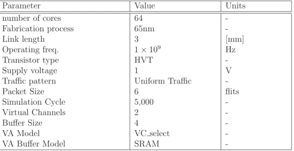
Table 3.2: Simulation Condition for On-chip Energy consumption
Parameter Value Units
number of cores 64 -
Fabrication process 65nm -
Link length 3 [mm]
Operating freq. 1×10⁹ Hz
Transistor type HVT -
Supply voltage 1 V
Traffic pattern Uniform Traffic -
Packet Size 6 flits
Simulation Cycle 5,000 -
Virtual Channels 2 -
Buffer Size 4 -
VA Model VC select -
VA Buffer Model SRAM -
consideration of ours to have a heterogeneous network design through the various layers of network. In our on-chip network, we have considered the high performance network and off-chip level is considered with the low powered networks. Hence, we have evaluated the static performance of various networks with diameter and average distance. Table 3.1 shows this analysis and it clearly confirms the 2D Flattened Butterfly (FB) has the superiority than any other networks. As this research focus on the efficient energy usage, we also focus on the energy consumption at the on-chip level to consider the suitable network as the on-chip level. To evaluate the on-chip energy consumption, we considered the Orion energy model [33] along with the garnet 1.0 network simulator [34]. This evaluation considers only 64 cores. Figure 3.2 shows this analysis and it confirms that 2D Flattened Butterfly (FB) ensure much better energy usage over the 2D and 3D networks.
On the other hand, Figure 3.3 shows the network energy usage for various high degree networks with 4K analysis. We considered the electrical links at the inter-chip level and optical links at the intra-rack level based on the evaluation of Section 2.4. This analysis is considered with the static performance parameter as the average distance and the total link power considering a single rack module. This analysis explains that 2DTorus network can ensure the low network energy usage over the other high degree networks and also shows slightly better than 2DMesh network. Hence, we would like to use ”2D Flattened Butterfly” as the on-chip network (with fixed router radix) and the 2DTorus network as the off-chip interconnect for our hierarchical interconnect.
0.00 0.05 0.10 0.15 0.20 0.25 0.30 0.0
2.0k 4.0k 6.0k
NetworkEnergyUsage(nJ)
Injection Rate (Flits/Cycle/Core)
2D Flattened Butterfly 3DMesh 2DMesh 3DTorus Direct Interconnect
Figure 3.2: On-chip Energy Consumption
Figure 3.3: Off-chip Energy Usage (static analysis)
3.2.3 Definition of Hierarchical Flattened Butterfly Network (HFBN)
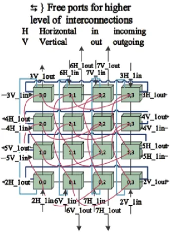
HFBN is considered as a hierarchical network as it maintains different topological pattern at the different levels of network structure. The lowest network level is (level-1 network) is defined as the basic module for HFBN, where each core maintains fixed number of radix and similar to 2D flattened butterfly architecture [35, 37]. On the other hand, the upper level of HFBN is considered with 2DTorus network. Hence, we named our net- work as the ”Hierarchical Flattened Butterfly Network (HFBN)”. This section defines the architectural pattern for HFBN, on-chip connections as well as for off-chips. HFBN maintains particular higher-level link pattern along with the 2DTorus upper level connec- tivity. On the other hand, the requirements for exa-scale system can be possible through interconnecting hundreds of millions of cores, which is certainly be possible by HFBN.
However, HFBN requires pre-defined port assignments for its upper level connectivity.
Figure 3.4 illustrates the interconnection philosophy of HFBN. However, we defined the HFBN through the definition network structure at various network levels and the equa- tions to obtain fixed structure of HFBN as below-
Figure 3.4: Interconnection of HFBN
Topological Definition: A HFBN(m, L, q) network, by definition is built with con- stant radix (similar to 2D flattened butterfly network) at the lowest level of the network followed by the 2DTorus interconnection at the upper level (with the particular connec- tivity consideration); where L considered as the level of hierarchy, q is the number of paired connectivity for each higher levels and m is any positive integer, which indicate the size of the basic module.
A HFBN(m, L, q) follows the exact definition for its certain level of connectivity-
Definition of HFBN Basic Module (BM): (2m ×2m) is the lowest network level, (m = is any positive integer)
Definition of HFBN Upper-level Connection: Lmax = 2×(2m −1)/q+ 1 is the maximum network size. Qmax = the maximum possible paired connectivity for any value of m; Qmax = 2(2m−1). 1≤q ≤ Qmax; depending on the value of q, HFBN(m, L, q) considers two set of configuration-
(a) IDEAL HFBN(m, L, q) when (2×(2m−1)mod q) = 0
(b) PARTIAL HFBN(m, L, q) when (2×(2m−1)mod q) ! = 0 (some exterior cores will be remained free).
Link Connectivity:
BM cores requires two digit for the formulation; the first is the Y-index, then the X-index. In general, in a Level-L HFBN, the core address can be represented by:
AL =
(ayL, axL) if Lmax ≥L≥1
More generally in a Level-L HFBN, the core address is represented by- A=AL AL−1 AL−2 ... ... ... A2 A1
= (a2L−1, a2L−2) (a2L−3,a2L−4)... ... (a3, a2) (a1, a0) (3.1) Here, the Level-1 is defined by core address (a1,a0), where a1 defines the core address for the Y-axis and then the X-axis with the a0. Higher level networks are two dimensional networks, hence we consider the first digit as the row index and then the second one is the column index. Now, if the address of a core N1 included in BM1 is represented as N1 = [(s2L−1,s2L−2)... ...(s3,s2) (s1, s0)] and the address of a core N2 included inBM2 is represented asn2 = [(d2L−1, d2L−2)... ...(d3,d2) (d1,d0)]. The coreN1 in BM1 and N2 in BM2 are connected if the following connections are satisfied forN2-
• Link for BM-
[(s2L−1, s2L−2)... ...(s3,s2) (s1, s0)] to [(s2L−1,s2L−2)... ...(s3, s2) (s1, s0±1 mod
2m)] where 2m > s0 >= 0,
[(s2L−1, s2L−2)... ...(s3, s2) (s1,s0)] to [(s2L−1, s2L−2)... ...(s3,s2) (s1±1 mod 2m,
s0)] where 2m > s1 ≥0
[(s2L−1,s2L−2)... ...(s3,s2) (s1,s0)] to [(s2L−1,s2L−2)... ...(s3,s2) ((s1+ 2m/2) mod 2m,s0)]
[(s2L−1, s2L−2)... ...(s3, s2) (s1, s0)] to [(s2L−1, s2L−2)... ...(s3, s2) (s1, (s0+ 2m/2) mod 2m )]
• Link for Higher Level Vertical Connections-
Connected Core, D= (((BM NL−1×2m)±x) mod BM NL)
• Link for Higher Level Horizontal Connections-
Connected Core, D= (((BM NL−1)±x) mod (BM NL−1×2m))
In case of higher level links,BMN (BMN = (2m×2m)) defines the number of cores in a basic module and Ldefines the core number of corresponding levels. For example, if m is 2, then the BMN = 16. On the other hand,x defines the source core number which is equal to (s2L−1×2m, s2L−2) ×BM NL−1 +... ...+(s3×2m+s2) ×BM N + (s1 ×2m + s0). The highest level of network, which can be obtained by a (2m×2m) BM is defined by Lmax =2×(2m−1)/q+ 1. Algorithm 1 shows the port assignment for upper-level connectivity for a particular basic module. And, the flowchart of this algorithm is given in Figure 3.5. This algorithm considers all of the exterior cores in the on-chip network to be interconnected with the other on-chip module. Algorithm 1 requires the input value of m and q. On the other hand, Lmax can be calculated from m and q. Function HIGHERLevel HFBN(m,q) allocates the particular core in the basic module for high level port connectivity, which requires the value of m, possible number of paired connectivity for each level. As the high level ports are being allocated by the exterior cores of the each basic module, this algorithm allocates the each possible port position for the higher level connectivity. In the initialize function, Lmax has been calculated and BMAX is the number of possible cores in each X or Y directions.
Algorithm 1 Higher Level port assignment for HFBN
HIGHERLevel HFBN(m,q); /* Main function to call with m, possible number of paired connectivity for each level */
initialize(q); /* Initializing the pre-defined ports */
for lv = 2 : Lmax; /* lv defines the network level */
fori= 1 : q; /* loop for making sure about all paired connectivity */
min dist= 65536;
if (lv ! = 2 andi= 1)
lvmh =port levelQ(lv−1,H, q); /* assign the previous level Horizontal port address */
lvmv =port levelQ(lv−1,V, q); /* assign the previous level Vertical port address */
else
lvmh =port levelQ(lv−1,H, i−1); /* assign the previous level Horizontal port address */
lvmv =port levelQ(lv−1,V, i−1); /* assign the previous level Vertical port address */
endif;
if (!availableQ(lv, ’V’, i)) /* check the current level port is already assigned or not */
for (x=0, y = 0; x≤ BMAX; x++, y++)
SaveXY( x, y, &save pv, &save ph, lvmv, lvmh, dist, &min dist); /* this function returns the y and x port position of current level throughsave phand save pv*/
endfor;
setHVLQ(save ph.y,save ph.x, lv, ’H’, i ); /* initialize the port */
setHVLQ(save pv.y,save pv.x, lv, ’V’, i); /* initialize the port */
endif;
endfor;
endfor;
end
SaveXY(x,y,∗save pv,∗save ph, lvmv, lvmh, dist,∗min dist); /* this function returns the y and x port position of current level throughsave phandsave pv */
if( LV[0][x] = 0 )
pv =set xy(0, x);ph=set xy(BM AX, x); /* consider the Vertical core position with respect to x */
dist = distance(pv, lvmh) + distance(ph, lvmv); /* compare the distance from the previous level outgoing ports */
if( dist< min dist )
save pv = pv; save ph= ph;min dist = dist; /* save the position */
endif;
ph =set xy(0, x);pv =set xy(BM AX, x); /* consider the horizontal core position with respect to x */
dist = distance(pv, lvmh) + distance(ph, lvmv); /* compare the distance from the previous level outgoing ports */
if( dist< min dist )
save pv = pv; save ph= ph;min dist = dist; /* save the position */
endif;
endif;
if( LV[y][0] = 0 )
pv =set xy(y,0);ph=set xy(y, BM AX); /* consider the Vertical core position with respect to y */
dist = distance(pv, lvmh) + distance(ph, lvmv); /* compare the distance from the previous level outgoing ports */
if( dist< min dist )
save pv = pv; save ph= ph;min dist = dist; /* save the position */
endif;
ph =set xy(y,0);pv=set xy(y, BM AX); /* consider the horizontal core position with respect to y */
dist = distance(pv, lvmh) + distance(ph, lvmv);
if( dist< min dist )
save pv = pv; save ph= ph;min dist = dist; /* save the position */
endif;
endif;
end;