Japan Advanced Institute of Science and Technology
JAIST Repository
https://dspace.jaist.ac.jp/
Title MgO担持チーグラー・ナッタ触媒を用いた超高分子量ポ
リエチレンの調製
Author(s) 播戸, 佑典
Citation
Issue Date 2019‑03
Type Thesis or Dissertation Text version ETD
URL http://hdl.handle.net/10119/15801 Rights
Description Supervisor:谷池 俊明, マテリアルサイエンス研究科
, 博士
Fabrication of Ultra-High Molecular Weight Polyethylene by MgO-Supported Ziegler-Natta Catalyst
YUSUKE BANDO
Japan Advanced Institute of Science and Technology
Doctoral Dissertation
Fabrication of Ultra-High Molecular Weight Polyethylene by MgO-Supported Ziegler-Natta Catalyst
Yusuke Bando
Supervisor: Professor Dr. Toshiaki Taniike
Graduate School of Materials Science
Japan Advanced Institute of Science and Technology
March 2019
Referee-in-chief: Associate Professor Dr. Toshiaki Taniike
Japan Advanced Institute of Science and Technology
Referees: Professor Dr. Shinya Maenosono
Japan Advanced Institute of Science and Technology
Associate Professor Dr. Shinohara Ken-ichi Japan Advanced Institute of Science and Technology
Senior Lecturer Dr. Shun Nisimura
Japan Advanced Institute of Science and Technology
Professor Dr. Hideki Kurokawa Saitama University
i
Preface
The present dissertation is the result of the studies under the direction of Associate Professor Dr. Toshiaki Taniike during 2015 - 2019. The purpose of this dissertation is to fabrication of ultra-high molecular weight polyethylene (UHMWPE) with MgO supported Ziegler-Natta catalyst. The first chapter is a general introduction according to the object of this study. Chapter 2 shows the small size UHMWPE synthesis using MgO/MgCl2/TiCl4 core-shell nano catalyst. Chapter 3 shows the 1 µm size UHMWPE particles synthesis using nano-dispersed Ziegler-Natta catalyst. Chapter 4 shows the good moldability UHMWPE particles synthesis using a catalyst prepared with MgO as a building block. The last chapter summarizes the conclusive items of this dissertation.
Yusuke Bando
Taniike Laboratory
School of Materials Science,
Japan Advanced Institute of Science and Technology
ii
Contents
Chapter 1
General Introduction
1.1. Introduction ... 2
1.2. Polyethylene ... 3
1.2.1. History of Polyethylene ... 3
1.2.2. Types and Characteristics of Polyethylene ... 5
1.2.3. Ultra-High Molecule Weight Polyethylene ... 7
1.2.4. Chain Entanglement of UHMWPE ... 8
1.3. Polymerization Catalyst ... 11
1.3.1. Ethylene Polymerization Catalyst ... 12
1.3.2. History of Ziegler-Natta Catalyst ... 13
1.3.3. Catalyst Preparation Method ... 17
1.4. Structure of MgCl2 Supported Ziegler-Natta Catalyst ... 20
1.4.1. Structure of MgCl2 ... 22
1.4.2. Catalyst Active Site ... 24
1.4.3. Mechanism of Catalyst Reaction ... 25
iii
1.4.4. Polymer Particle Growth and Fragmentation of Catalyst ... 27
1.5. Objective of This Study ... 31
Reference ... 33
Chapter 2 Synthesis of MgO/MgCl2/TiCl4 Core-Shell Nano Catalyst Using MgO Particles Abstract ... 38
2.1. Introduction ... 39
2.2. Experimental ... 44
2.2.1. Materials... 44
2.2.2. Catalyst Preparation ... 44
2.2.3. Polymerization ... 45
2.2.4. Characterization ... 47
2.3. Results and Discussion... 51
2.4. Conclusions ... 71
Reference ... 72
iv
Chapter 3
Nano-dispersed Ziegler-Natta catalysts for 1 µm-sized ultra-high molecular weight
polyethylene particles
Abstract ... 76
Introduction ... 77
Experimental ... 82
3.2.1 Materials... 82
3.2.2 Surface Modification of MgO and Catalyst Preparation ... 83
3.2.3 Polymerization ... 85
3.2.4 Characterization ... 86
3.2.5 Compression Molding ... 88
Result and Discussion ... 90
Conclusions ... 110
Reference ... 111
v
Chapter 4
Preparation of Multigrained MgO-Supported Ziegler-Natta Catalyst via Spray Dry
Method
Abstract ... 116
4.1. Introduction ... 117
4.2. Experimental ... 121
4.2.1. Materials... 121
4.2.2. Catalyst Preparation ... 121
4.2.3. Polymerization ... 122
4.2.4. Compression Molding ... 123
4.2.5. Characterization ... 124
4.3. Results and Discussion... 126
4.4. Conclusions ... 141
Reference ... 143
vi
Chapter 5
General Conclusion
5.1. General Summary ... 147
5.2. Conclusion ... 149
Achievements ... 151
Acknowledgment ... 154
Sub-Theme Report………...……..155
1
Chapter 1
General Introduction
2
1.1. Introduction
Polyolefin is one of general purpose plastics consists of only of hydrogen and carbon that does not contain any harmful substance such as chlorine and aromatic compounds.
Therefore, recycling and reuse of polyolefin are easier than other materials, and they are low environmental impact materials [1]. Also, since its characteristics as a material are inexpensive, lightweight, high melting point, high chemical resistance, high strength, excellent mechanical properties, and high moldability, the application range is used automotive parts, package, and containers. It has been demanded further development of polyolefin material in the future as well [2]
Figure 1 Production volume of polyolefin
3
1.2. Polyethylene
Polyethylene is a polymer having a structure, in which ethylene is basically linearly polymerized. It has the most straightforward chemical structure among polymers, and it is used for various applications in the world including containers and packaging films.
The basic skeleton consists only of repeating methylene, but differences in average molecular weight, number of branches, crystallinity, etc. differ depending on the manufacturing method, and density, thermal properties, mechanical properties, etc. are also different accordingly. In general, substances with low molecular weight are swollen by hydrocarbon solvents, but those with high molecular weight are excellent in chemical resistance. It is also excellent in electric insulation.
1.2.1. History of Polyethylene
Polyethylene was adventitiously synthesized as a waxy solid from the pyrolysis of diazomethane by Pechmann in 1898 [3]. It was later confirmed by Bamberger and Tschirner to be polyethylene (low-density polyethylene).
Eric William Fawcett and Reginald Oswald Gibson of the ICI company in the United Kingdom in 1933 discovered a way to polymerize ethylene by heating ethylene to high temperature and pressure [4]. After that, industrial production began at the beginning
4
of 1940 by the du Pont Company and UCC Company of the United States. This polymerizes ethylene at a pressure as high as 1000 atmospheres or higher, so it is called high pressure polyethylene. Polyethylene obtained by this production method is also called low density polyethylene (LDPE) because of its low density [5].
Meanwhile, in the early 1950s Robert Banks of Philips Petroleum of America and J.
Paul Hogan developed a method to polymerize ethylene at 30-100 atm. In 1953, ethylene polymerization at atmospheric pressure became possible by Karl Ziegler of the Max Planck petroleum coal research institute in West Germany, and the production cost drastically decreased. Polyethylene synthesized by these two production methods is collectively called medium and low pressure polyethylene. It is also called high density polyethylene (HDPE) because it can obtain high density compared to low density polyethylene.
Later on, Mitsui Petrochemical (1970) and, by UCC in the United States (1977) synthesized polyethylene different from conventional medium and low pressure polyethylene. Since this polyethylene is called a third polyethylene and is a low density polyethylene obtained by copolymerizing a large amount of linear polyethylene with an α-olefin containing a large amount of short side chain, thus called linear low density (LLDPE) It is also called.
5
1.2.2. Types and Characteristics of Polyethylene
The molecular structure of polyethylene is greatly affected by its production method.
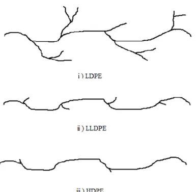
Polyethylene has a simple crystal structure, but characteristics are greatly affected by the number and structure of branches of the polymer chain. Therefore, it is mainly classified into LDPE, HDPE, and LLDPE (Figure 2).
Figure 2 Structure of polyethylene
6
Table 1 Characteristics of various PE [6]
Density (g·cm‒3)
Melting point (°C)
Crystallinity (%)
LDPE 0.915-0.930 106-120 40-60
LLDPE 0.910-0.940 120-125 40-60
HDPE 0.940-0.965 125-135 65-80
LDPE has a structure with many long chain branching, and its degree of crystallinity is low, and the spread of molecules in solution is small. On the other hand, HDPE is linear with few branches, and therefore has a higher degree of crystallinity than LDPE and widens the molecule in solution. Unlike LDPE, LLDPE has a low density but a linear structure and is synthesized by copolymerization with an α-olefin, so that it is possible to control the number and length of branching with α-olefin. Therefore, it is an intermediate structure between LDPE and HDPE. Since the LLDPE is linear, the spread of molecules in solution is about as wide as HDPE.
Generally, polyethylene having a molecular weight of several hundred to several hundreds of thousands are produced on an industrial scale. Those whose molecular weight has been increased to several million or more will be distinguished from each other, they are classified as ultra-high molecular weight polyethylene (UHMWPE).
7
UHMWPE is structurally similar to HDPE and is a linear polymer with few branches, but its molecular weight has been increased to several million or more. Therefore, the entanglement of the molecular chains is large, the melt viscosity is extremely high, and the fluidity is poor.
1.2.3. Ultra-High Molecule Weight Polyethylene
UHMWPE has excellent properties such as high chemical resistance and light weight of polyethylene, improved impact resistance, high wear resistance, and self-lubricating property [7]. Therefore, it is classified as an engineering plastic. Because of having such excellent properties, it is added to rubber, cosmetics, etc., and it is used for artificial implants, bulletproof vests, chemical pumps, and the like [8]. However, since UHMWPE has a very high molecular weight, entanglement of molecular chains is large, it shows extremely high melt viscosity and low fluidity. As a result, it is impossible to be peretallized. Moreover, general molding methods such as extrusion and blowing cannot be used for UHMWPE, requiring special molding methods such as compression and ram extrusion [8]. In these molding methods, the polymer particles directly obtained by the polymerization are thermally fused as they are. However, since UHMWPE melts the surface of the particles even when heat is applied, delamination due
8
to uneven structure formed by grain boundary formed at the time of molding and bonding failure between particles is problematic [9]. Industrially, UHMWPE is synthesized by slurry polymerization with Ziegler-Natta catalyst [10,11].
1.2.4. Chain Entanglement of UHMWPE
The molding process of UHMWPE is almost impossible to use conventional methods such as injection molding due to the very high melt viscosity [12]. Therefore, it is processed by powder metallurgy such as sintering. This process requires knowledge of the diffusion mechanism of very long molecules and is necessary to improve the mechanical properties and durability of the sintered part. In the sintering of the polymer powder, initially, densification of the powder concerning particle wetting takes place. In the case of a semi crystalline polymer, it is efficiently carried out below the melting temperature [13]. Next, cross-crystallization is performed by re-crossing due to diffusion of polymer chains at the particle interface. At this stage, the polymer particles melt and time and temperature play an important role [14].
The diffusion mechanism of polymer chains is generally explained by reptation [15].
Reptation is also used to explain the mechanism of crack sealing and polymer chain diffusion of welding [16–19]. Reptation strongly depends on the molecular weight of
9
the polymer. Also, it is influenced by the mutual penetration distance of polymer chains during fusion, which depends on the temperature and time of sintering. Co- crystallization is the growth of new microcrystals across the interface bonding the original powder particles. The final mechanical properties of the semicrystalline sintered body depend on the reconfiguration of the entwining network and the formation of the crystal network in the interface region of the sintered powder [20–22].
In the case of UHMWPE, there is the consequence that sintering depends much more on temperature than time. Also, it is said that a long diffusion time is not necessary in order to impart high ductility to the bonding interface and sintered powder. The ultimate mechanical properties of the sintered UHMWPE are dominated by the formation of crystal networks in the interfacial region of the sintered powder rather than a reconfiguration of the entangled network. These results indicate that there is a phenomenon that enables polymer chain diffusion and crossing in a much shorter time than Reptation [23–26]. It is explained by the melting explosion phenomenon which actively promotes the diffusion of polymer chains. This phenomenon has been demonstrated by molding UHMWPE crystallized in a solvent, and it has been shown that the bulk properties recover much sooner than the predicted time. It has been confirmed that this phenomenon also appears in UHMWPE powder. During the melt explosion
10
process, the entanglement of chains from adjacent particles due to the lateral movement of the initially entangled polymer chain loops is much faster than the encounters of the ends at both ends along that tube, It promotes recovery of the bulk properties at a much shorter time scale than the long chain reaction time [27–29].
11
1.3. Polymerization Catalyst
Current polyolefin industry consists of various technologies such as catalyst, manufacturing process, molding process, additives etc. The catalyst for polymerizing olefins is a heterogeneous catalyst such as a Ziegler-Natta catalyst and a Phillips catalyst, and a homogeneous catalyst such as a metallocene catalyst, which is an organometallic complex containing cyclopentadienyl anion. Among them, Ziegler-Natta catalyst, in particular, has excellent characteristics such as high activity, high stereo specificity, wide molecular weight distribution, excellent polymer morphology, low cost. Therefore, it is an important catalyst not only used for many propylene polymerizations but also for a synthesis of high-density polyethylene and linear low-density polyethylene.
Table 2 Characteristic of HDPE Catalyst type Mw/Mn
Number of long chain branches (/10000 carbon)
Phillips catalyst 6-15 ca. 1
Ziegler-Natta catalyst 3-6 0
Metallocene catalyst 2-3 0-1
12
However, the correlation between the structure and performance of Ziegler-Natta catalyst is not well understood, and the guiding principle of development is difficult to stand. Therefore, catalyst development is carried out by preparing a catalyst and conducting a polymerization performance test. Repeated try-and-error is being carried out in an inefficient way of obtaining a catalyst with good performance. Therefore, it is strongly desired industrially to elucidate the correlation between the structure and performance of the catalyst. Ziegler-Natta catalyst has been developed for nearly 60 years, but related technological development and basic research are vigorously carried out.
1.3.1. Ethylene Polymerization Catalyst
Polyethylene is classified according to its density and production method. LDPE is polymerized by ethylene polymerization using a chromium catalyst or Ziegler-Natta catalyst or copolymerization of a small amount of comonomer with ethylene by LDPE by radical polymerization under high temperature and pressure, and HDPE is added and more comonomer is added to copolymerize LLDPE is obtained. A Phillips catalyst which is one of the chromium based catalysts is prepared by depositing chromium oxide on a silica · alumina carrier and heating it in a gas flow of oxygen, nitrogen, carbon
13
dioxide or the like to activate it. Ziegler-Natta catalyst uses titanium as an active species, and magnesium chloride is used as a carrier.
1.3.2. History of Ziegler-Natta Catalyst
Figure 3 History of performance improvement of Ziegler-Natta catalyst
In 1953, Karl Ziegler succeeded ethylene polymerization under normal temperature and pressure by using TiCl4/AlR3 which is a mixture of titanium tetrachloride and an organoaluminum compound as a catalyst [30]. Then in 1954 Giulio Natta successfully synthesized a polypropylene with an isotactic content of 30 to 40% with a similar catalyst
14
system [31]. Synthesis of polypropylene with a high isotactic content of 80 to 90% was achieved by TiCl3/AlR3 catalyst using titanium trichloride instead of soluble titanium tetrachloride. The TiCl3/AlEt2Cl catalyst initially used in ethylene polymerization had activity of about 2 to 3 kg-PE/g-Ti
In 1963 Solvay Company in Belgium succeeded in greatly improving the activity by immobilizing and supporting titanium tetrachloride utilizing the surface hydroxyl group of hydroxy chloride magnesium chloride [32]. This made it possible to omit the catalyst removal step. It was realized for the first time when the decalcification process was placed on an industrial plant. Then in the late 1960s Magnesium chloride-loaded Ziegler-Natta catalyst was developed by Montecatini of Italy and Mitsui Petrochemical.
This catalyst is still used for polyethylene production.
In the case of polymerization of propylene, control of stereospecificity and regiospecificity other than polymerization activity is required for the catalyst. When the active species is titanium Propylene polymerization usually proceeds with 1,2-addition.
Therefore, the 2,1-addition hardly progressed and it is not necessary to consider position specificity. On the other hand, about 10% of atactic polypropylene is formed as a by- product. For this reason, research to improve stereospecificity was done from the late 1950's. As a result, in 1972 Solvay Company extracted β-type titanium trichloride with
15
isoamyl ether and reacted with titanium tetrachloride to obtain δ-type titanium trichloride.
It succeeded in obtaining a catalyst complex having a large surface area, porosity and very high activity. This catalyst is called Solvay TiCl3, the polymerization activity is improved, and by-production of atactic polypropylene can also be suppressed to about 3 to 4%. Solvay TiCl3 is the first example of a second generation catalyst.
Improvements have been repeated thereafter, and it is still used in some manufacturing processes now.
The third generation Ziegler-Natta catalyst has combined an electron donating compound typified by ethyl benzoate as a third component, was developed by Montecatini and Mitsui Petrochemical Industries in 1971-1974. As a method for preparing this catalyst, there is a method of co-grinding magnesium chloride, titanium tetrachloride and an external donor complex, and a method of treating a co-pulverized product of MgCl2 and ED with TiCl4 heated and then washing with an organic solvent.
The characteristic of this catalyst system is that there is no need decalcification because of its high activity. AlEt3-ED-based activators come to be used instead of AlEt2Cl for propylene polymerization. From 1980 to 1981 it was found that the specific combination of ED used for solid catalyst preparation and ED used during polymerization is important. As an example it was found that introduction of organic acid diester into
16
MgCl2/TiCl4 catalyst and addition of alkoxysilane compound during polymerization gave excellent stereospecificity. However, it was necessary to remove atactic polypropylene by 6 to 10% of the whole depending on usage conditions. Therefore, catalyst development has focused on finding a more efficient combination of catalyst preparation and a more effective combination of electron donating compounds.
Later, in the early 1980s a new combination of electron donor compounds was discovered. Catalyst preparation is carried out using an alkyl phthalate compound as an internal donor. The catalyst was developed in which alkoxysilane compounds or silyl ether compounds are added as external donors during polymerization. This catalyst system had better balance between productivity and stereospecificity than ethylbenzoate system. This catalyst system was originally called ultra-high activity third generation type catalyst. However, it was later called the fourth-generation Ziegler-Natta catalyst because it used a completely different electron-donating compound from the third- generation Ziegler-Natta catalyst. In the latter half of the 1980's, a new type of electron donor compound, 1,3-diether compound, was used. When used as an internal donor component, it exhibits extremely high activity and stereospecificity without requiring any external Lewis base. This catalyst system is called a fifth generation catalyst.
17
1.3.3. Catalyst Preparation Method
Since 1970, MgCl2-supported Ziegler-Natta catalyst had been developed, not only aiming for higher activity catalyst but also stabilization of active behavior and morphology control of obtained polymer had become required. Therefore, a method of preparing a catalyst having a better form was developed. The method for preparing MgCl2 -based Ziegler-Natta catalyst can be broadly divided into three main preparation methods. They are called co-grinding method, dissolution precipitation method and chemical reaction method, respectively.
In the co-grinding method, a catalyst component is pulverized using a ball mill. As the characteristics of the particles obtained by the co-grinding method, the catalyst form cannot be controlled because it is pulverized, it has a nonuniform and irregular form, and a catalyst with a wide particle size distribution can be obtained. In addition, the polymerization performance of this catalyst behaves such that the activity immediately decreases after rapid activation at the beginning of polymerization. Since the form of the catalyst is heterogeneous, there is a feature that the polymer form obtained becomes worse. However, since it is simple and inexpensive compared to other preparation methods, it had been mainly used in the early stage of development of MgCl2 supported Ziegler-Natta catalyst. Since the problem of the form of a polymer obtained and the
18
activity behavior are not stable, it was possible to use it in slurry polymerization, but because it is not suitable for gas phase polymerization or bulk polymerization with higher productivity, the frequency of use was diminished. It is currently used industrially as a very small part of slurry polymerization.
In the dissolution-precipitation method, a solution of a magnesium compound such as MgCl2 or Mg(OR)2, Mg(OCOR)3, MgR, magnesium silylamide compound is prepared using alcohol, trialkyl phosphate or the like as a solvent [33]. Treating the solution with a halogenating agent to precipitate MgCl2, treating it with an internal donor and TiCl4, or mixing an internal donor with a solution and treating it with TiCl4 to obtain a catalyst component. It is possible to obtain catalysts whose morphology is controlled by this method. Further, by halogenating the solution with TiCl4, the catalyst component can be obtained in one step, which is a cost saving and saving process. The characteristic of this catalyst is that the surface is smooth and the bulk density is high. Polymer particles having a high bulk density and a small amount of fine powder can be obtained. Since this catalyst has strong particle strength, it retains its particle shape even when it is used for high productivity polymerization methods such as gas phase polymerization and bulk polymerization. Therefore, it is used industrially favorably and is one of the most used catalyst preparation methods. The chemical reaction method treats solid Mg(OR)2 or
19
Mg(OR)Cl and an internal donor in aromatic or halogenated solvent with an excess of TiCl4. MgCl2 is produced by the reaction of the magnesium compound with TiCl4 [34].
The by-product Ti(OR)4 is removed by washing to obtain a catalyst component. It is possible to obtain catalysts whose morphology is controlled by this method. The form of the Mg compound as the reaction precursor become the form of catalyst particles.
Therefore, the catalyst form can be controlled by controlling the form of the Mg compound used. Industrially, Mg(OEt)2 is prepared by a method of converting Mg(OEt)2 to MgCl2 with a halogenating agent. The catalyst obtained by this method has a form of Mg(OEt)2 as a catalyst form. Therefore, it is easy to control the form of the catalyst particle. This catalyst has high activity and excellent copolymerization performance. Further, since it is easy to control the form, it is often used for study of catalyst form. Industrially, prepolymerization is necessary, but it can be used for gas phase polymerization and bulk polymerization. It is often used when copolymerization performance is required as compared with dissolution precipitation method.
20
1.4. Structure of MgCl
2Supported Ziegler-Natta Catalyst
The Ziegler-Natta catalyst is generally composed of MgCl2 as a carrier, TiCl4 as a catalyst, and a donor for controlling stereoregularity. From the 3rd generation Ziegler- Natta catalyst and later, MgCl2 has used as a carrier material to achieve a drastic improvement in activity. This is because not only an increase in the active surface like the general catalyst system but also an electron donating effect on the active species has been exerted.
Figure 4 Relationship between activity of polymerization and electronegativity of support [35]
21
Soga investigated the influence on the activity of various metal chlorides in propylene polymerization, indicating that there is a correlation between electronegativity and activity. Among the metal chlorides, MgCl2 has the lowest electronegativity and high activity. From this fact, magnesium chloride is most frequently used as a carrier in the Ziegler-Natta catalyst. The crystal structure of TiCl4 and MgCl2 are similar in hexagonal system and the ion radii of Ti4+ (0.68 Å) and Mg2+ (0.65 Å) are about the same. It is believed that Ti, Cl atom enters the defective part of the MgCl2 crystal of the catalyst.
22
1.4.1. Structure of MgCl
2Figure 5 XRD pattern of various MgCl2;
(a) α -MgCl2 (b) δ-MgCl2 activated from α -MgCl2 by ballmilling, (c) δ-MgCl2 activated α -MgCl2 by chemical reaction method [36]
MgCl2 has two kinds of crystal structures, a commercial α type, and an unstable β type . The α type has a CdCl2 type crystal structure. A structure in which magnesium ions are arranged in gaps of octahedrons in which chlorine ions are arranged in a face centered cubic lattice structure, takes a layered structure in which a layer of magnesium ions is
23
sandwiched between layers of chloride ions. The β type has a hexagonal close-packed packing structure [37]. Actually, the crystal structure of magnesium chloride used for Ziegler-Natta catalyst is activated to δ-MgCl2 [38,39]. In this crystal structure, the layer of the Cl-Mg-Cl structure shows an irregular structure due to the transition and rotation, and the crystal size is about several tens of nm [40]. In the X-ray spectrum, a halo pattern is shown between the cubic structure and the hexagonal close-packed structure.
Figure 6 Structure model of MgCl2-supported ZN catalysts
Zannetti showed a model of metal chloride which was closely packed with Cl ions in the layered structure which was continuously disordered and overlapped [41]. This model is compatible with the experimental X-ray spectrum and it can be considered that the activated MgCl2 is composed of very small lamella. It is known that (100) and (110)
24
planes are preferentially exposed on the catalyst surface, and Mg2+ ions having various degrees of coordination unsaturation exist. Therefore, activated MgCl2 is considered to be aggregates of very small crystallites.
1.4.2. Catalyst Active Site
TiCl4 is alkylated with TEA in the preparation of the catalytic system consisting of the first discovered TEA and TiCl4. The produced ethyltitanium compound is unstable and releases ethane and ethylene to be reduced to TiCl3 which is a trivalent titanium compound. Further, the generated TiCl3 is similarly alkylated, the reduction reaction proceeds, and a divalent titanium compound is produced. Therefore, it is known that 4, 3, and 2 valence titanium compounds were produced. In this way, it is thought that a very complicated reaction is occurring in the Ziegler catalyst formation reaction process.
Activation of MgCl2 supported Ziegler-Natta catalyst using TEA produces various atomically dispersed Ti(II) and Ti(III) species containing 3 to 5 ligands, these ligands being chloride and a mixture of ethyl ligands and contains 1 to 3 vacancies. In addition, it is known that small clusters of reduced Ti(III)XClY are formed during interaction with TEA. Among these species, catalytic sites containing Ti(II) have also been proposed for ethylene polymerization. The pentacoordinated Ti(III) atom fixed on the 110 face
25
characterized by the ethyl ligand and the open orientation is widely considered to be the active site of olefin polymerization [42–46].
1.4.3. Mechanism of Catalyst Reaction
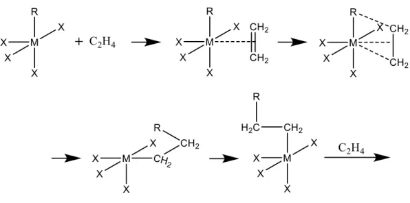
Figure 7 Ethylene polymerization
where M and R are Active metal and alkyl group, respectively
26
Figure 8 Elementary reactions of ethylene polymerization
The mechanism of the polymerization reaction is known as the mechanism of Coossee, and ethylene is first activated by coordinating to the ethylethane compound [47,48].
Next, it is thought that new ethylene is inserted between the ethyl group and titanium and the reaction starts. Polymerization occurs by repeating new ethylene insertion again.
As a termination reaction, there is a method by β-hydrogen elimination reaction, but the active point is not inactivated, new ethylene is added again and a new reaction is started.
In addition, although it may be stopped by chain transfer reaction to ethylene, also in this case, new ethylene is inserted again and the reaction is started. In addition to ethylene, hydrogen and alkylaluminum cause chain transfer reaction. Chain transfer reaction by hydrogen is mainly used for controlling the molecular weight of polyethylene.
27
1.4.4. Polymer Particle Growth and Fragmentation of Catalyst
The growth of the polymer particles progresses by exposing the activation site by fragmentation of the catalyst particles. Therefore, it is possible to control the shape and size of polymer particles to some extent through the catalyst. Mainly, when homogeneous crushing of a catalyst or growth of a polymer occurs at each catalyst surface at a stable speed, it is well known as a replica phenomenon in which polymer particles reproduce physical properties such as the shape and structure of catalyst particles [49].
This phenomenon is related to how catalyst particles collapse and diffuse as polymerization progresses. Such growth is possible only when several conditions are met. The conditions are a high surface area, homogeneous high porosity, good mechanical strength enough to disintegrate during polymerization, homogeneous activity distribution, the fact that the monomer easily reaches the interior reaching the interior.
Several single particle growth models are shown to understand the growth process of polymer particles [50–55]. The most common of these models is the multi grain model.
28
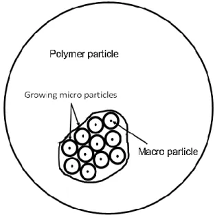
Figure 9 Schematic drawing multi grain model
Nagel first showed the multigrain model [56]. It was later expanded to include fragmentation by Laurence and Chiovetta, and mass and heat transfer were taken into account [57]. In this model catalyst particles are formed by aggregates of macro particles. Polymerization begins at the activation site on the macro particle surface and is surrounded by growing polymer. The growing polymer pushes out the previously generated polymer particles from within the microparticles. In this way, the polymer particles grow.
Many studies have been done to understand the process of fragmentation of catalyst particles. Regarding the porous carrier, catalytic activity abruptly increases at the start of polymerization, and a polymer is formed in the pores. As a result, monomer transport
29
to the catalytically active site is delayed, and a decrease in activity is caused. This deactivates may also occur due to inactivation of the catalyst by heating of the catalyst particles due to reaction heat at the beginning of the polymerization. It is known that fragmentation is affected by polymerization temperature. When the temperature is raised, the initial activity increases but persistence decreases. Fragmentation is observed to depend on the structure of the catalyst carrier. However, due to its complicated catalyst structure, it has not been fully elucidated yet.
Figure 10 Two types of the fragmentation of catalyst [58]
It has been observed that the catalyst having low mechanical strength is mainly cracked, the distribution of fragmented size becomes uniform, and the form of the catalyst particle is sufficiently replicated. This mechanism of fragmentation is called Continuous bisection model. In this mechanism, since the porous catalyst can be broken easily, the
30
resistance of monomer transport is not essential, and almost no polymer is clogged in the pores. On the other hand, a catalyst having a relatively high mechanical strength using silica or a polymer as a carrier has low activity. This mechanism of fragmentation is called Shrinking core model. In this case, the catalyst particles are not easily broken, and the maximum of the outer layer pore is clogged with the polymer so that the spread of the monomer is delayed. Actual fragmentation is considered to progress simultaneously in these two models, and it is considered to be affected by monomers and polymerization conditions.
31
1.5. Objective of This Study
UHMWPE is excellent in impact strength, sliding property and abrasion resistance, and it is used for artificial hip joints and machine parts. In molding process of UHMWPE which is inferior in fluidity at the time of melting, a special method (compression or ram extrusion) using polymer powder is required, and defects due to particle interface are a problem. Also, the produced UHMWPE particles are hard and difficult to crush further finely by grinding. Therefore, UHMWPE with small particle size can only be obtained by controlling the particle size during polymerization. In the case of heterogeneous catalysts, it is known that the morphology of the polymer depends on the catalyst particles, and the size of the polymer is proportional to the catalyst particle size and polymerization activity used. Reducing the particle size of the polymer and narrowing the particle size distribution is one of the methods to solve problems such as defective joining of grain boundaries when performing compression molding. However, at present, there are many processes for preparing the Ziegler-Natta catalyst, and advanced techniques are necessary because the catalyst form changes due to multivariate factors. Catalyst preparation using magnesium oxide (MgO) nanoparticles can be easily prepared only by chlorinating the surface of MgO particles, and the particle morphology does not change before and after treatment. In addition, MgO nanoparticles are prepared by a build-up
32
method, and can obtain a nanometer size particle with narrow particle size distribution.
Therefore, it is possible to obtain a catalyst having a small particle size and a narrow particle size distribution without going through complicated steps such as conventional Ziegler-Natta catalyst preparation. Hence, the MgO-supported Ziegler-Natta catalyst can be a very excellent catalyst which can easily obtain UHMWPE particles having a small particle size and narrow particle size distribution. In chapter 2, the agglomeration of the catalyst particles in the polymerization solvent was partially suppressed by treating the MgO surface with methyloleate. Polymerization using the catalyst successfully obtained UHMWPE particles, which shows a catalyst system featuring simpler and simpler preparation methods than conventional catalyst systems for synthesis of UHMWPE. In Chapter 3, successfully prepared a truly nano-dispersed Ziegler-Natta catalyst in a polymerization solvent by adding an appropriate organic modifier to the MgO surface. UHMWPE synthesized by this catalyst was 1-2 μm fine particles. The UHMWPE particles had significantly lower melting temperatures, resulting in several advantages in processing, such as enhanced bonding in compression molding. In Chapter 4, secondary aggregates of catalyst particles were formed using spray drying in order to improve catalyst handling. Two kinds of catalysts of different forms were prepared. Spherical particles could be obtained.
33
Reference
[1] C. Vasile, Handbook of Polyolefins, 2000.
[2] P. Galli, G. Vecellio, J. Polym. Sci. Part A Polym. Chem., 2004, 42, 396–415.
[3] H. v. Pechmann, Berichte Der Dtsch. Chem. Gesellschaft, 1898, 31, 2950–2951.
[4] E. W. Fawcett, R. O. Gibson, M. W. Perrin, J. G. Paton, E. G. Williams, GB 471590 19370906, 1937.
[5] K.B. Sinclair, in:, Macromol. Symp., Wiley-Blackwell, 2001, pp. 237–261.
[6] P.S. Chum, K.W. Swogger, Prog. Polym. Sci., 2008, 33, 797–819.
[7] J. M. Kelly, J. Macromol. Sci. Part C, 2002, 42, 355–371.
[8] J. Furmanski, L.A. Pruitt, Polymer, 2007, 48, 3512–3519.
[9] T. Morikawa, F. Xu, K. Ninomiya, H. Matsuda, M. Yoshikawa, Chem. Pharm.
Bull. (Tokyo)., 2004, 52, 494–497.
[10] R.L. Jones, M. Armoush, Macromol. Symp., 2009, 283–284, 88–95.
[11] J.C. Somberg, J. Molnar, Am. J. Ther., 2008, 15, 292–295.
[12] A.E. Likhtman, T.C.B. McLeish, Macromolecules, 2002, 35, 6332–6343.
[13] K. Al Jebawi, B. Sixou, R. Séguéla, G. Vigier, C. Chervin, J. Appl. Polym. Sci., 2006, 102, 1274–1284.
[14] M. Bousmina, H. Qiu, M. Grmela, J.E. Klemberg-Sapieha, Macromolecules,
34 1998, 31, 8273–8280.
[15] P.G. De Gennes, J. Chem. Phys., 1971, 55, 572–579.
[16] P.G. De Gennes, Tribol. Ser., 1981, 7, 355–367.
[17] R.P. Wool, K.M. O’Connor, J. Appl. Phys., 1981, 52, 5953–5963.
[18] S. Prager, M. Tirrell, J. Chem. Phys., 1981, 75, 5194–5198.
[19] K. Jud, H.H. Kausch, J.G. Williams, J. Mater. Sci., 1981, 16, 204–210.
[20] S. Rastogi, D.R. Lippits, G.W.M. Peters, R. Graf, Y. Yao, H.W. Spiess, Nat.
Mater., 2005, 4, 635–641.
[21] D. Romano, N. Tops, E. Andablo-Reyes, S. Ronca, S. Rastogi, Macromolecules, 2014, 47, 4750–4760.
[22] Z. Bartczak, P.F.M. Beris, K. Wasilewski, A. Galeski, P.J. Lemstra, in:, J. Appl.
Polym. Sci., Wiley-Blackwell, 2012, pp. 4155–4168.
[23] Y.-Q. Xue, *, and T. A. Tervoort, P.J. Lemstra, 1998,.
[24] C.W.M. Bastiaansen, H.E.H. Meyer, P.J. Lemstra, Polymer, 1990, 31, 1435–
1440.
[25] P.J. Barham, D.M. Sadler, Polymer, 1991, 32, 393–395.
[26] T. Deplancke, O. Lame, F. Rousset, I. Aguili, R. Seguela, G. Vigier, Macromolecules, 2014, 47, 197–207.
35
[27] B.P. Rotzinger, H.D. Chanzy, P. Smith, Polymer, 1989, 30, 1814–1819.
[28] J. Loos, M. Arndt-Rosenau, U. Weingarten, W. Kaminsky, P.J. Lemstra, Polym.
Bull., 2002, 48, 191–198.
[29] P. Smith, H.D. Chanzy, B.P. Rotzinger, J. Mater. Sci., 1987, 22, 523–531.
[30] K. Ziegler, E. Holzkamp, H. Breil, H. Martin, Angew. Chem., 1955, 67, 541–547.
[31] G. Natta, P. Pino, P. Corradini, F. Danusso, G. Moraglio, E. Mantica, G.
Mazzanti, J. Am. Chem. Soc., 1955, 77, 1708–1710.
[32] J. P. Hermans, P. Henrioulle, US 3769233, 1973.
[33] M. Ferraris, F. Rosati, S. Parodi, E. Giannetti, E. Albizzati, US 4399054, 1983.
[34] M. Kioka, N. Kashiwa, JP 2537506, 1996.
[35] Y. Doi, K. Soga, M. Murata, E. Suzuki, Y. Ono, T. Keii, Polym. Commun., 1983, 24, 244–246.
[36] V.D. Noto, S. Lavina, D. Longo, M. Vidali, Electrochim. Acta, 1998, 43, 1225–
1237.
[37] I.W. Bassi, F. Polato, M. Calcaterra, J.C.J. Bart, Zeitschrift Fur Krist. - New Cryst. Struct., 1982, 159, 297–302.
[38] M. Vittadello, P.E. Stallworth, F.M. Alamgir, S. Suarez, S. Abbrent, C.M. Drain, V. Di Noto, S.G. Greenbaum, Inorganica Chim. Acta, 2006, 359, 2513–2518.
36
[39] V. Di Noto, S. Bresadola, Macromol. Chem. Phys., 1996, 197, 3827–3835.
[40] U. Giannini, Makromol. Chem., Suppl, 1981, 5, 216–229.
[41] R. Zannetti, C. Marega, A. Marigo, A. Martorana, J. Polym. Sci. Part B Polym.
Phys., 1988, 26, 2399–2412.
[42] E. Groppo, K. Seenivasan, C. Barzan, Catal. Sci. Technol., 2013, 3, 858–878.
[43] E. Morra, E. Giamello, S. Van Doorslaer, G. Antinucci, M. D’Amore, V. Busico, M. Chiesa, Angew. Chemie - Int. Ed., 2015, 54, 4857–4860.
[44] R. Mülhaupt, Macromol. Chem. Phys., 2003, 204, 289–327.
[45] L.L. Böhm, Angew. Chemie - Int. Ed., 2003, 42, 5010–5030.
[46] K. Ziegler, E. Holzkamp, H. Breil, H. Martin, Angew. Chem. Int. Ed. Engl., 1955, 67, 426–426.
[47] P. Cossee, J. Catal., 1964, 3, 80–88.
[48] P. Cossee, Tetrahedron Lett., 1960, 1, 12–16.
[49] P. Galli, P.C. Barbè, L. Noristi, Die Angew. Makromol. Chemie, 1984, 120, 73–
90.
[50] E.L. Hoel, C. Cozewith, G.D. Byrne, AIChE J., 1994, 40, 1669–1684.
[51] R. Galvan, M. Tirrell, Chem. Eng. Sci., 1986, 41, 2385–2393.
[52] D. Singh, R.P. Merrill, Macromolecules, 1971, 4, 599–604.
37
[53] W.R. Schmeal, J.R. Street, AIChE J., 1971, 17, 1188–1197.
[54] J.W. Begley, J. Polym. Sci. Part A-1 Polym. Chem., 1966, 4, 319–336.
[55] T. F. McKenna, J. B. P. Soares, Chem. Eng. Sci., 2001, 56, 3931–3949.
[56] E. J. Nagel, V. A. Kirillov, W. H. Ray, Ind. Eng. Chem. Prod. Res. Dev., 1980, 19, 372–379.
[57] R. L. Laurence, M. G. Chiovetta, PolymIn Polymer Reaction Engineering:
Influence of Reaction Engineering on Polymer Properties, Wiley-Blackwell, 1985.
[58] B. Horáčková, Z. Grof, J. Kosek, Chem. Eng. Sci., 2007, 62, 5264–5270.
38
Chapter 2
Synthesis of MgO/MgCl 2 /TiCl 4 Core-Shell Nano Catalyst Using MgO Particles
Abstract
In this chapter, MgO/MgCl2/TiCl4 core–shell catalysts are employed for the production of ultrahigh molecular weight polyethylene (UHMWPE) particles, motivated by their advantages including simple preparation, ease of morphology control, and a dramatically reduced Cl content. It is found that the MgO/MgCl2/TiCl4 core–shell catalysts can provide UHMWPE at a reasonable activity, but the agglomeration of the catalyst particles leads to poor morphology of the UHMWPE. The dispersion problem is largely alleviated by modifying MgO nanoparticles with methyl oleate (MO). Thus, the MO‐
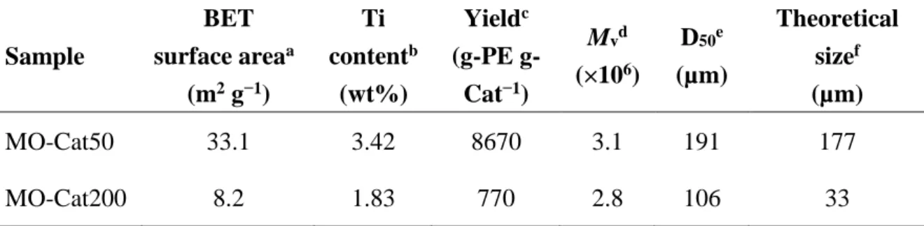
modified MgO/MgCl2/TiCl4 core–shell catalyst successfully affords UHMWPE particles of 100–200 µm at a high yield of 8670 g‐PE g‐Cat−1.
39
2.1. Introduction
Heterogeneous olefin polymerization catalysts have been widely used to manufacture a wide variety of polyolefins owing to their economic advantages and the ease of polymer morphology control. The morphology of polymer particles, for instance, the particle size, the particle size distribution and shape, is important for the efficiency of the polymer production in plants. In particular, polymer particles with a narrow particle size distribution are desirable to improve the flow ability in the transportation line and to prevent the reactor fouling. It is well‐known that the morphology of polymer particles
can be controlled through the morphology of catalyst particles [1–3]. Polymerization initiates at active sites that are located on accessible surfaces of the catalyst particles.
Once the polymer is formed, it forces the catalyst to fragment, leading to the exposure of fresh active sites. The repetition of this process within multigrained particles lets the morphology of polymer replicate that of the catalyst particles, known as “replicating
phenomena” [4–6].
In the past decade, the synthesis of fine particles of polyolefins has gained increasing attention due to potential applications: unlike a typical pellet form, fine particles are mainly used as a modifying additive, in which a large specific surface area and fine structure of polymer particles contribute to improve properties of other materials. For
40
example, micron‐sized polyethylene wax is used as an additive for paints, inks, and powder coatings to enhance the esthetics of a protective finish [7], slip properties, and scratch resistance, while the addition of micron‐sized ultrahigh molecular weight polyethylene (UHMWPE) enhances the self‐lubricating properties and abrasion
resistance of matrix polymers [8]. Though emulsion polymerization is most widely employed for accessing polymer fine particles [9], it is hardly applicable in the case of olefin polymerization owing to the catalyst deactivation in the presence of a polar solvent.
Fine particles are also formed by a solvent deposition technique, where a polymer solution is brought to a supersaturated state either by adding a poor solvent or by rapid quenching [10–12]. The process is applicable to many types of polymers and easy to control the morphology of resultant fine particles by process conditions, but a required large volume of solvents is not economically viable. Consequently, a method to directly obtain polyolefin fine particles in catalyzed olefin polymerization is most preferred in industry.
Under the assumption of the replication in olefin polymerization, the size of polymer particles obtained is expressed in proportion to Y1/3·DCat, where Y and DCat represent the polymer yield per gram‐catalyst and the size of catalyst particles, respectively.
Considering the productivity of a plant as well as the factor of 1/3 for Y relative to unity for DCat, the size of catalyst particles, DCat, must be the main parameter to manipulate the
41
polymer particle size. Likewise, reduction in the catalyst particle size without scarifying the activity and morphological integrity during polymerization becomes a key target to obtain fine polymer particles. In general, commodity grades of UHMWPE have particle sizes of 140–300 µm, and produced using Ziegler–Natta catalysts possessing particle sizes around 5–20 µm. While microfine grades of UHMWPE below 80 µm can be accessed by catalysts with the sizes of a few‐to‐several micrometers. In obtaining size‐
and morphology‐controlled Ziegler–Natta catalysts, a number of preparation protocols
have been developed, most frequently based on reprecipitation of a Mg precursor solution under a controlled condition. Various types of Mg precursor solutions have been proposed such as a MgCl2·nAlRCl2·mAlCl3 solution prepared from the dissolution of magnesium chloride, alkyl aluminum dichloride, and aluminum trichloride at high temperature [13], a Mg‐ and Ti‐alkoxide solution prepared from the dissolution of magnesium ethoxide with titanium tetrabuthoxide followed by the dilution in hydrocarbon solvent [14], a sort of a Grignard compound with a formula of MgPh2·nMgCl2·mBu2O that was obtained by reacting metallic Mg with chlorobenzene and dibutyl ether in the presence of iodine as an initiator [15], and etc. The reprecipitation of a solution and subsequent or simultaneous titanation can be performed in single or multiple steps, using a halogenating agent and/or a Ti‐containing halogen
42
compound to form a solid catalyst. The chlorination at a low temperature [15], step‐
wise heating [16], and the application of a special mixer [17] are typical strategy to control the morphology of catalyst particles during the reprecipitation. Furthermore, a high speed shearing treatment (>10 000 rpm) either during the formation of a solid support [18] or after forming a solid catalyst [19] is additionally required, when the particle size down to a few‐to‐several micrometers is desired. Likewise, existing protocols can more
or less afford catalysts with controlled morphology and particle sizes suitable for the production of UHMWPE fine particles, but reduction in the particle size has necessitated complicated chemical formulas as well as technically demanding and/or elaborate processes.
In previous study, a simple preparation route for Ziegler–Natta catalysts was reported, in which magnesium oxide (MgO) crystalline nanoparticles were treated with TiCl4 to form MgO/MgCl2/TiCl4 core–shell catalysts for studying the structure–performance relationship between the surface area and activity in propylene polymerization [20,21].
This catalyst system was considered as promising for the production of UHMWPE particles based on the following reasons:
(i). The particle size of the catalysts can be easily controlled through the size of original MgO nanoparticles.
43
(ii). The catalyst preparation is quite simple, i.e., only the chlorination of preformed MgO nanoparticles with TiCl4.
(iii). Even though the catalyst behaves similar to conventional Ziegler–Natta catalysts, the chlorine content per gram‐catalyst is dramatically reduced.
In this chapter, I report the first application of the MgO/MgCl2/TiCl4 core–shell catalysts in ethylene polymerization, especially focusing on the production of UHMWPE particles. It was found that the MgO/MgCl2/TiCl4 core–shell catalysts were able to produce UHMWPE at a reasonable activity, and that the modification of MgO supports with methyl oleate largely improved the dispersibility of the catalyst particles in a hydrocarbon medium, thus affording UHMWPE particles of 100–200 µm.
44
2.2. Experimental 2.2.1. Materials
MgO samples with the particle size of 50, 60, and 200 nm were obtained from Wako Pure Chemical Industries Ltd. They were used after dehydration in vacuo at 160°C for 2 h. Titanium tetrachloride (TiCl4), kerosene, methyl oleate (MO), o‐dichlorobenzene (ODCB), and decahydronaphthalene of research grades were used without further purification. Ethylene of a polymerization grade was purchased from Hokurikuekikasangyou Co., Ltd. and used as received. Triisobutylaluminium (TiBA) and triethylaluminium (TEA) were donated by Tosoh Finechem Co. n‐Heptane was used after dehydration by passing through a column of molecular sieve 4A and N2
bubbling for 2 h.
2.2.2. Catalyst Preparation
Pre‐dehydrated MgO (2.0 g) powder was reacted with 30 mL of TiCl4 at 140°C for 2 h
under stirring at 250 rpm. The obtained solid was washed with 100 mL of heptane for ten times and kept as a slurry in heptane. The catalysts were named as Cat50, Cat60, and Cat200, where the numbers specified the particle size of the employed MgO samples.
In another set of experiments, MgO powder was treated with MO prior to the catalyst
45
preparation. MgO (10.0 g) was sonicated in 25 mL of kerosene at room temperature for 10 min. Thereafter, 8.0 mL of MO was added to the suspension followed by refluxing at 160°C for 1 h. The obtained solid was washed with 100 mL of ODCB for five times to obtain MO‐treated MgO samples (denoted as MO‐MgO50 and MO‐MgO200). The catalyzation was performed as described above, except 50 mL of ODCB was co‐added together with TiCl4. The catalysts were named as MO‐Cat50 and MO‐Cat200, which corresponded to the use of MO‐MgO50 and MO‐MgO200, respectively.
Scheme 1 Catalyst preparation
2.2.3. Polymerization
Slurry polymerization of ethylene was first performed in a 1 L stainless steel reactor equipped with a mechanical stirrer. Heptane (200 mL) as a solvent was injected into the
46
reactor under N2 and then saturated with 0.5 MPa of ethylene at 50°C for 30 min.
Following the addition of 2.0 mmol of TiBA as an activator, 30 mg of a catalyst was introduced to the reactor to start polymerization. The polymerization was continued for 30 min at 50°C and 0.5 MPa of ethylene pressure, and finally terminated by the addition of acidic ethanol. The obtained polymer samples were named as PE50, PE60, and PE200, which corresponded to the use of Cat50, Cat60, and Cat200, respectively.
The polymerization using the MO‐treated catalysts was conducted at an optimized
condition to obtain a reasonable polymer yield: using the same reactor, heptane was introduced into the reactor under N2 blanking. TEA was then introduced at the concentration of 2.0 mmol L−1. The solvent was saturated with 0.8 MPa of ethylene at 70°C for 30 min before charging the catalyst slurry to start polymerization. The catalyst amount was fixed at 10 mg with the total solvent volume kept at 500 mL. The polymerization was carried out at 70°C under 0.8 MPa of ethylene pressure for 2 h. The obtained polymer was filtered and dried in vacuum at 60°C for 6 h. The polymer samples were named as MO‐PE50 and MO‐PE200, which corresponded to the use of MO‐Cat50 and MO‐Cat200, respectively.
47
Scheme 2 Polymerization condition
2.2.4. Characterization
The morphology of MgO and catalyst particles was observed by transmission electron microscopy (TEM, Hitachi H‐7100) operated at an accelerating voltage of 100 kV. TEM samples were prepared by dropping a suspension of samples in ethanol or heptane to a carbon film reinforced copper grid and subsequent drying. The particle size and the particle size distribution of MgO and catalyst samples were analyzed by light scattering (Horiba Partica LA‐950V2) in a suspension form using ethanol or heptane as a solvent.
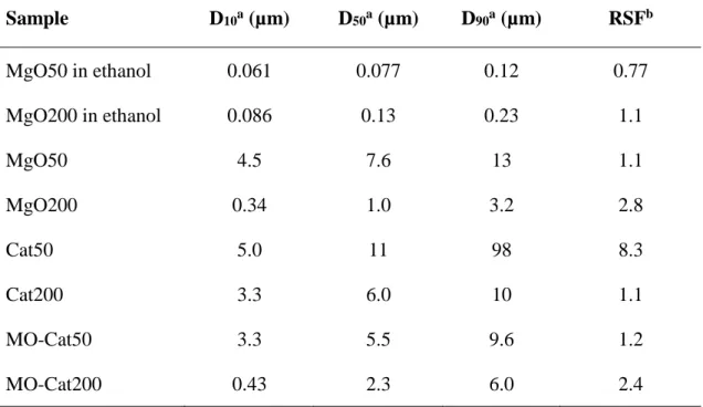
The particle size was reported as D10, D50, and D90, which corresponded to the particle size at 10%, 50%, and 90% of the cumulative volume [6]. The particle size distribution
48
was reported as a relative span factor (RSF) [6] calculated based on
(1) N2 adsorption/desorption isotherms of the catalyst were acquired using BELSORP‐
max at 77 K. The sample was out gassed at 80°C for 3 h prior to the measurement [20,21]. The surface area of the sample was calculated by the Brunauer–Emmett–Teller (BET) equation. The presence of MO on MgO nanoparticles was observed by attenuated total reflectance infrared spectroscopy (ATR‐IR, Perkin Elmer Spectrum 100 FT‐IR) in the range of 500–4000 cm−1. After repetitive washing of MO‐MgO with
ODCB, the powder was dried under vacuum and subjected to the measurement. The Ti content of the catalyst was analyzed by ultraviolet–visible spectrometry (UV–vis, Jasco V670). The catalyst (50 mg) was dissolved in an aqueous solution of hydrochloric acid and sulfuric acid. Thereafter, 200 µL of hydrogen peroxide was added to form a peroxotitanium complex that exhibited the absorption band at 410 nm. The Ti content was determined based on the intensity at 410 nm, using an externally acquired standard curve.
The morphology of polymer powder was observed by scanning electron microscopy (SEM, Hitachi S‐4100) operated at an accelerating voltage of 20 kV. Polymer powder was dispersed on a carbon tape and subjected to Pd–Pt sputtering for 100 s before the
49
measurement. The viscosity‐average molecular weight (Mν) of polymer samples was obtained based on ASTM 4020D, except the fact that the relative viscosity of a polymer solution was measured using an electromagnetically spinning viscometer (EMS, Kyoto Electronics Manufacturing, EMS‐100). In the EMS measurement, a polymer sample was dissolved in decahydronaphthalene at 0.02 g L−1 and at 150°C. Subsequently, 300 µL of the solution was transferred to a glass vial containing an aluminum ball. The viscosity of the polymer solution was measured at 135°C based on the frustrated rotation of the aluminum ball in the viscous solution. The relative viscosity (ηrel), specific viscosity (ηsp), intrinsic viscosity ([η]), and Mν were derived according to Equations (2)–
(5)
(2) (3) (4) (5) where C is the concentration of the polymer dissolved in decahydronaphthalene.
The melting temperature (Tm) of the obtained polymer in the nascent form and melt‐
crystallized form was acquired using differential scanning calorimetry (Mettler Toledo DSC 822). In the case of the nascent form, Tm was obtained from the melting endotherm
50
in the first heat cycle, where a sample was heated to 180°C at the heating rate of 10°C min−1 under N2 flow. After cooling to 50°C at the cooling rate of 10°C min−1, the second heat cycle was applied at the same heating rate to acquire Tm in the melt‐crystallized form.
The polymer particle size was analyzed by light scattering in ethanol suspension. The theoretical size of polymer particles was estimated according to Equation (6)
(6) where dCat and dPE are the densities of the catalyst and polymer, respectively. Y is the polymerization yield. DPE and DCat are the particle sizes of the polymer and catalyst, respectively.
51
2.3. Results and Discussion
The MgO/MgCl2/TiCl4 core–shell catalysts comprise of a thin MgCl2/TiCl4 catalytic layer covering MgO crystalline cores. As the catalyzation proceeds on the outermost surfaces of MgO cores, the morphology of catalyst particles well retains that of the original MgO particles. In addition to this, nonporous and nonfragmentable characters assure the correspondence between the BET surface area and practically available surface area of the catalysts during polymerization [22]. In the previous papers, a series of MgO/MgCl2/TiCl4 core–shell catalysts were had prepared to have different surface areas using MgO nanoparticles of different sizes so as to clarify a linear relationship between the surface area and propylene polymerization activity.
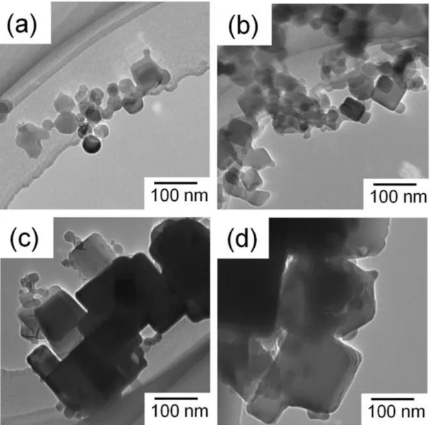
Here, a similar attempt was extended to ethylene polymerization. Three MgO/MgCl2/TiCl4 core–shell catalysts were synthesized using MgO samples with the particle sizes of 50, 60, and 200 nm. MgO nanoparticles utilized in this work are commercially available samples having relatively broad particle size distributions. In TEM images, it was confirmed that the morphology of the catalyst samples well preserved that of the original MgO samples, i.e., polygonal and cubic nanoparticles for MgO50 and Cat50, and for MgO200 and Cat200, respectively (Figure 1).
52
Figure 1 TEM images of MgO and catalyst particles:
a) MgO50, b) Cat50, c) MgO200, and d) Cat200
In Figure 2, N2 adsorption/desorption isotherms for the MgO and catalyst samples were featured with a plateau of an adsorption profile at low relative pressure and an unrestricted sorption at high relative pressure, which can be classified as a type II adsorption isotherm for nonporous materials based on the IUPAC classification [23].
53
Figure 2 N2 adsorption/desorption isotherms for MgO50, Cat50, MgO200, and Cat200
The plateau at low relative pressure results from the transition from mono to multilayer adsorption of N2 on the outermost surfaces of the nanoparticles, while the unrestricted adsorption at high relative pressure attributes to the N2 condensation in interparticle voids among the nanoparticles. Below p/p0 = 0.3, the isotherms for the catalyst samples fully overlapped with those of the corresponding MgO samples, indicating that the catalyzation
54
hardly affected the surface area of the nanoparticles. Meanwhile, the upward deviation of the isotherms for the catalysts with respect to those of the MgO samples suggested that the formation of the catalyst overlayer affected the agglomeration structure of the nanoparticles. It is notable that the flowability of the catalyst samples in a dry state was much lower than that of the corresponding MgO samples. Obviously, the ionic nature of the catalyst overlayer enhanced the attraction among the nanoparticles. Table 1 summarizes the results of the characterization. As explained above, the BET surface areas were almost identical between the MgO and catalyst samples of the corresponding sizes, and the Ti content tended to increase along the surface area.
Table 1 Characteristics and ethylene polymerization performance of MgO/MgCl2/TiCl4 samples
Sample BET surface areaa (m2 g−1)
Ti contentb (wt%)
Yieldc (g-PE g-Cat−1)
Mvd
(×106)
Cat50 33.5 (34.3)e 0.47 1270 3.4
Cat60 29.1 (29.8)e 0.43 1100 3.1
Cat200 8.4 (8.1)e 0.17 5.44 3.0
aAcquired from the N2 adsorption isotherm.
bDetermined based on UV-vis spectroscopy.
cPolymerization conditions: Ethylene pressure = 0.5 MPa, heptane = 300 mL, TiBA = 2.0 mmol, catalyst = 30 mg, T = 50C, t = 0.5 h.
dCalculated based on Equations (1)(4) using the relative viscosity measured by an EMS viscometer.
eThe values in parentheses are the BET surface areas of original MgO samples.
![Table 1 Characteristics of various PE [6]](https://thumb-ap.123doks.com/thumbv2/123deta/6097859.1076044/19.892.211.681.183.395/table-characteristics-various-pe.webp)
![Figure 4 Relationship between activity of polymerization and electronegativity of support [35]](https://thumb-ap.123doks.com/thumbv2/123deta/6097859.1076044/33.892.297.622.572.922/figure-relationship-activity-polymerization-electronegativity-support.webp)
![Figure 10 Two types of the fragmentation of catalyst [58]](https://thumb-ap.123doks.com/thumbv2/123deta/6097859.1076044/42.892.165.728.575.788/figure-types-fragmentation-catalyst.webp)