CopyrightⒸ2017 一般社団法人 日本機械学会
[No.17-5] 日本機械学会 M&M2017 材料力学カンファレンス 講演論文集 〔2017.10.7-9,(札幌)〕
0705
三次元有限要素法による異方性材料および 等方性材料の接合構造に対する応力解析
(異方性材料のヤング率と特異応力場の強さの関係)
Stress Analysis for orthotropic-isotropic bonded structure model Based on Three-dimensional Finite Element Method
(Relationship between Young’s modulus of orthotropic
material and intensity of stress singularity)
〇学 鋤柄あかね
* 1
,倉橋貴彦* 1 Akane SUKIGARA* 1 , Takahiko KURAHASHI* 1
*1 長岡技術科学大学
Nagaoka University of Technology
Electronic package is made by bonding of different material such as semiconductor chip, resin and metal. When the force act on the surface of bonded structure, the stress concentration occurs near the interface edge. The region of the stress concentration and the point of the interface edge are referred to as the singular stress field and the singular point, respectively. It appears that the singular stress field or the singular point is one of cause of fracture of the bonded structure and affects the electrical characteristics of the circuit. Therefore, it is necessary to investigate the suitable structure by the stress analysis. Silicon used as semiconductor chip is orthotropic material. In this study, the relationship between the material properties of the orthotropic material and intensity of singularity is investigated. The purpose of this study is to investigate on the singular stress field for three dimensional orthotropic-isotropic bonded structure. The stress analysis is carried out based on the finite element method.
Key Words : Singular stress field, Singular point, orthotropic, Bonded structure, FEM
1. 緒 言
電子機器基板に用いる電子パッケージはシリコンチップ,レジン,金属など,特性の異なる材料の接合により 構成される.接合体に荷重を加えると界面端角部近傍に応力集中が生じ,接合体の破壊や回路の電気特性変動の 一因となるため,最適な構造を検討する必要がある.シリコンは立方晶系の結晶であり材料定数の軸が直交して いることから,本研究ではシリコンを直交異方性材料とみなし,シリコンとレジンの接合体を想定した 3 次元直 交異方性-等方性材料接合体モデルに対して
FEM
による応力解析を行う.2. 3DFEM
による応力解析次元直交異方性材料とレジンの接合体モデルに対して
3DFEM
に基づく応力解析を行う.計算モデルは先行研 究のものを用いる(Fig.1)(1). Material1を直交異方性材料,Material2をレジンとする.3. 数 値 実 験
本研究では
Fig.1
に示すモデルに対して,2方向の弾性定数を変化させ,Z軸方向に引張荷重10MPa
を加えた 時の応力成分σ
zzを解析することにより,弾性定数の方向が界面の応力特異性に与える影響を調べる.Table1
に計 算モデルの条件を示す. 検討において変える弾性定数の方向は次のとおりとする.CaseA 引張軸方向 (Z
軸方向)CaseB 界面に平行方向(Y
軸方向)CopyrightⒸ2017 一般社団法人 日本機械学会
[No.17-5] 日本機械学会 M&M2017 材料力学カンファレンス 講演論文集 〔2017.10.7-9,(札幌)〕
Table2~Table4
に材料定数を示す.レジンの材料定数は文献を参照した(1).直交異方性材料の材料定数は先行研究の例を参考に,弾性定数を数値的に定め,ポアソン比,横弾性定数は一定とした(2)(3).
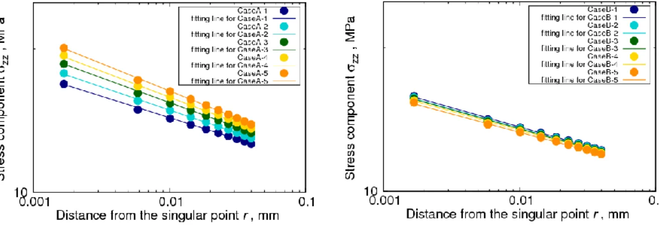
Fig.2
に,界面上45°方向の界面端角部からの距離 r
に対するZ
軸方向の応力成分σ
zzを示す.CaseA-1はE
z=11GPa,CaseA-2
はE
z=12GPa
と,Ezを1GPa
ごとに変えている.CaseBについても同様にE
yを1GPa
ごとに変 えている.特異応力場における応力分布は一般に式(1)で表されることから,式(1)によるフィッティングを行い,特異応力場の強さ
K
zzとヤング率E
z(CaseA),E
y(CaseB)の関係を整理する(Fig.3).
zz K
zzr
(1)ここに,
λ
は特異性のオーダを示す.結果として,CaseAの引張軸方向に弾性率(Ez)を増加させた場合には,応力成分
σ
zzの値も増加し,特異場の強 さK
zzも増加した(Fig.3 (a)).一方CaseB
に示す界面に平行方向の弾性定数(Ey)の値を増加させた場合は,応力成分 σ
zzの値は減少する結果となった.合わせて応力特異場の強さK
zzも弾性率(Ey)が増加するごとに小さくなること
がわかった(Fig.3 (b)).そこで,各ケースにおける弾性定数が
15GPa
の場合における特異点近傍の界面上の応力成分σ
zzの分布の違 いを調べた.結果をFig.4
に示す.CaseAでは角部に応力集中が見られるが,CaseBではCaseA
に比べ応力集中 が緩やかになっていることを確認できた.(a) Finite element model (b) Computational model Fig.1 Finite element and computational models
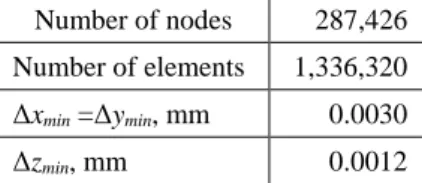
Table 1 Computational condition Table 2 Material properties Number of nodes 287,426
Number of elements 1,336,320 Δx
min=Δy
min, mm 0.0030
Δz
min, mm 0.0012
Table 3 Young’s modulus of orthotropic material Young’s modulus, GPa
E
xE
yE
zCase A 10 10 11
~15
Case B 10 11~15 10
Table 3 Modulus of transverse elasticity and Poisson ratio of orthotropic material ν
xy=ν
xz=ν
yx=ν
yz=ν
zx=ν
zy0.3
G
xy=G
yz=G
zx, GPa 7.69
Material Young’s modulus, GPa Poisson ratio Material 1
Orthotropic material (See Table 3) (See Table 3)
Material 2 Resin 2.74 0.38
CopyrightⒸ2017 一般社団法人 日本機械学会
[No.17-5] 日本機械学会 M&M2017 材料力学カンファレンス 講演論文集 〔2017.10.7-9,(札幌)〕
(a) CaseA (b) CaseB
Fig. 2 Stress component σ
zznear vertex of interface
(a) CaseA (b) CaseB
Fig. 3 Relationship between intensity of singularity K
zzand Young’s modulus E
y(a) CaseA (b) CaseB
Fig. 4 Distribution of stress component σ
zznear vertex of interface edge
CopyrightⒸ2017 一般社団法人 日本機械学会
[No.17-5] 日本機械学会 M&M2017 材料力学カンファレンス 講演論文集 〔2017.10.7-9,(札幌)〕
4. 結 論
本稿では,シリコンとレジンの接合体を想定した
3
次元直交異方性-等方性材料接合体モデルに対してFEM
による応力 解析結果を示した.引張軸方向の弾性定数(E
z)と界面に平行方向の弾性定数(E
y)を変えて検討した結果,界面に平行方向の弾
性定数
(E
y)の値を増加させた場合は特異点近傍の応力成分 σ
zzの値は減少し,また特異場の強さK
zzも小さくなることがわかった.
謝 辞
本研究の計算結果は,九州大学情報基盤研究開発センターの高性能演算サーバシステム
PRIMERGY CX400
により得ら れたものである.九州大学情報基盤研究開発センターのスタッフの方々に対して謝意を表す.文 献