Synchronization Phenomena in Two Rings of Coupled Three van der Pol Oscillators
Daiki Nariai, Tran Minh Hai, Yoko Uwate and Yoshifumi Nishio
Dept. Electrical and Electronic Eng.,Tokushima University, 2-1 Minami-Josanjima,
E-mail:{nariai, minhhai, uwate, nishio}@ee.tokushima-u.ac.jp
Abstract—In this study, we investigate synchronization phe- nomena in two rings of van der Pol oscillators coupled by resistors. We propose novel coupled oscillatory system such as two rings of van der Pol oscillators coupled by resistors. We focus on coupling strength of coupled van der Pol oscillators.
From computer simulations, we investigate how synchronization phenomena changes by changing the coupling strength. We observe various synchronization phenomena by changing the coupling strengths. We demand to control the synchronization phenomena by changing the coupling strength.
I. INTRODUCTION
Synchronization phenomena of coupled oscillators is the most familiar phenomena. Among them, synchronization phe- nomena of van der Pol oscillators is similar to natural phe- nomena. Because it is easy to observe the synchronization phenomena of van der Pol oscillators by changing frequency.
Synchronization phenomena of van der Pol oscillator has been studied in various fields since ancient times, such as in elec- trical systems, in mechanical systems, in biological systems and basically everywhere. For example, firefly luminescence, heartbeat, and so on. We explain synchronization phenomena with concrete descriptions in heatbeat. Heat pulsative in a normal way because all cardiac muscle cell synchronize.
Many researchers have proposed various coupled oscillatory networks of van der Pol oscillators. We focus on coupling strength of coupled oscillatory networks consisted of two kinds of van der Pol oscillatiors.
The van der Pol oscillator is simple ciruit. It is consisted of resistor, inductor, capacitor and nonlinear resistor. It was invented by electrical engineer Balthasar van der Pol. Equation of van der Pol is second-order differential equation.
In this study, we propose novel coupled oscillatory system such as two rings of van der Pol oscillators coupled by resistors. First ring is consisted of three van der Pol oscillators connected by resistors. Second ring is consisted of three van der Pol oscillators connected by inductors. By computer simu- lations, we investigate synchronization phenomena observed in the proposed circuit system by changing the coupling strength.
II. SYSTEM MODEL
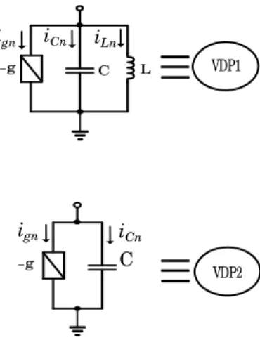
Figure 1 shows two circuits which were used in my research.
We use six van der Pol oscillators (three VDP1 and three
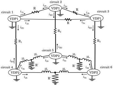
VDP2). Figure 2 shows a system model with van der Pol oscillators (VDP1 and VDP2). We use two ring circuits of van der Pol oscillators, three VDP1 of first ring are connected by resistors, three VDP2 of second ring are connected by inductors. First and second ring are connected by resistor (R1, R2,R3). We observe synchronization phenomena of adjacent oscillators. We investigate synchronization phenomena how changing by changing the value of resistors.
-g
-g C L VDP1
VDP2 ign iCn iLn
ign iCn
C
Fig. 1. Circuit of van der Pol oscillators.
The circuit equation of first ring are given as follows:
−ign−icn−iLn = ian+ibn+irn
LdidtLn = vn
vn−vi = (ian−ib(i))R vn−vj = (ibn−ia(j))R vn−vn+3 = (irn−ir(n+3))R
(1)
The circuit equation of second ring are given as follows:
−ign−icn = ian+ibn+irn
vn−2Ldidtan = −(ian+ib(i))R′ vn−2Ldidtbn = −(ibn+ia(j))R′ vn−vn−3 = (irn−ir(n−3))R
(2)
- 15 -
IEEE Workshop on Nonlinear Circuit Networks December 9-10, 2016
circuit 2
circuit 3
circuit 5
circuit 6 circuit 4
circuit 1
VDP1
VDP2 VDP1
VDP1
VDP2
VDP2 R
R R
R`
R`
R`
R1
R2
R3
2L 2L 2L
2L 2L
2L i1a
i1b i3a
i3b
i2a i2b
i4a
i4b
i5b
i6a
i6b
i5a iR4
iR5
iR3
iR1
iR2
Fig. 2. Circuit model.
where n denotes the number of circuit and n = 1,2,3,4,5,6. i denotes the number of circuit and i = 2,3,1,5,6,4. j denotes the number of circuit and j = 3,1,2,6,4,5.
Nonlinear resistor defined as follows:
ign = −g1vn+g3v3n (3) By changing the variables and parameters.
t=√
LGτ, vn =√
g1
3g3xn, in=
√g1C 3g3Lyn, ε=g1
√C L, α= R1
√L C, β =R′
√
C
L, γn =R1
n
√
L C
(4)
The normalized equations of first ring are given as follows:
˙
xn = ε(xn−x3n)−yn−γ(xn−xn+3) +α(−xn+xi+xj)
˙
yn = xn
(5)
The normalized equations of second ring are given as follows:
˙
xn = ε(xn−x3n)−yan
−ybn+γ(xn−xn−3)
˙
yan = xn−β(yan+yb(i))
˙
ybn = xn−β(ybn+ya(j))
(6)
where n denotes the number of VDP1 and VDP2, n = 1,2,3,4,5,6. The parameters ε, α, β, and γ denote the
coupling strengh of the inductor, resistor R, resistor R′ and resistor Rn.
III. SIMULATION RESULTS
The simulation result of the system model are shown from Fig. 3 to Fig. 6. The value of the parameters are set to ε= 0.05,α= 0.05,β= 0.05.
In case of γ1 = γ2 =γ3 = 0.02, we conduct simulation, each one at a different initial value. In Fig. 3, synchronization phenomena is observed in circuit 1 and circuit 4. However, in Fig. 4, synchronization phenomena is observed in circuit 2 and circuit 5.
x
3x
3x
1x
1x
2x
2x 4 x 5 x 6 x 3 x 2
x 1 x
5x
5x
4x
4x
6x
6Fig. 3. Phase difference (γ1=γ2=γ3= 0.02)
x
2x
2x
1x
1x
3x
3x
1x
2x
3x
6x
5x
4x 6 x 6 x 4 x 4
x 5
x 5
Fig. 4. Phase difference (γ1=γ2=γ3= 0.02)
By chaging γ1,γ2 andγ3, we can control synchronization phenomena regardless of initial value.
In case of γ1= 0.02, γ2 = 0.005, γ3= 0.02, synchroniza- tion phenomena is observed in circuit 4 and circuit 6 without reference to initial value. In this result, when we increase two of γ1 and γ3, three oscillators of first ring and two of three oscillators of second ring are synchronized.
- 16 -
x
2x
2x
3x
3x
1x
1x
4x
5x
6x
3x
2x
1x
5x
5x
6x
6x
4x
4Fig. 5. Phase difference (γ1= 0.02, γ2= 0.005, γ3= 0.02)
In case of γ1 = 0.001, γ2 = 0.0001, γ3 = 0.02, in- phase synchronization phenomena is observed in oscillators of first ring, 3-phase synchronization phenomena is observed in oscillators of second ring. In this result, when we increase one of γ3, three oscillators of first ring become in phase synchronization phenomena, oscillators of second ring become 3-phase synchronization phenomena.
x
2x
2x
3x
3x
1x
1x
1x
2x
3x
6x
5x
4x 4 x 4
x 5
x 5 x 6
x 6
Fig. 6. Phase difference (γ1= 0.001, γ2= 0.001, γ3= 0.02)
We observe various synchronization phenomena by chang- ing the coupling strengths. In this results, when we demand two oscillators of second ring to synchronize, we strengthened up two of γ1, γ2 andγ3. When we demand three oscillators of second ring to become 3-phase synchronization phenomena, we strengthened up two ofγ1,γ2 and γ3. Therefore we can control synchronization phenomena by coupling strengths.
IV. CONCLUSIONS
We have proposed a system model using two rings of coupled three van der Pol oscillators coupled by resistors or
inductors. We can control the synchronization phenomenon by varying the coupling strengths. When three coupling strengths (γ1, γ2, γ3) equal, synchronization phenomena are observed by changing initial value. However when we increase two of γ1,γ2andγ3, three oscillators of first ring and two oscillators of second ring are synchronized. When we strengthened up one of γ1, γ2 and γ3, oscillators of first ring become in- phase synchronization phenomena, oscillators of second ring become 3-phase synchronization phenomena. In the future, we investigate synchronization phenomena using other parameters and analyze my circuit model.
REFERENCES
[1] Y. Uwate, Y. Nishio, ”Two van der Pol Oscillators Coupled by Chaotically Varying Resistor” Proceedings of International Workshop on Nonlinear Dynamics of Electronic Systems (NDES’06), pp. 189-192, Jun. 2006.
[2] K. Marsumura, T. Nagai, Y. Uwate, Y. Nishio, ”Analysis of Synchroniza- tion Phenomenon in Coupled Oscillator Chains” Proceedings of IEEE International Symposium on Circuits and Systems (ISCAS’12), pp. 620- 623, May 2012.
[3] K. Oi, Y. Uwate, Y. Nishio, ”Synchronization Phenomena in Coupled van der Pol Oscillators by Adding Oscillators with Different Frequen- cies” Proceedings of IEEE Workshop on Nonlinear Circuit Networks (NCN’15), pp. 1-3, Dec. 2015.
[4] K. Oi, Y. Uwate, Y. Nishio,”Synchronization Phenomena of Parametri- cally Excited Oscillators with Small Mismatch in Random Network” Pro- ceedings of IEEE Workshop on Nonlinear Circuit Networks (NCN’14), pp. 49-51, Dec. 2014.
[5] K. Oi, K. Ago, Y. Uwate, Y. Nishio,”Effect of the Hub in Complex Networks of Coupled Parametrically Excited Oscillators with Disper- sion” Proceedings of IEEE Workshop on Nonlinear Circuit Networks (NCN’15), pp. 11-14, Dec. 2015.