Doctor Thesis
Shibaura Institute of Technology
Corrosion Behavior Evaluation of
Surface Modified Type 304 Stainless Steel
September 2014
ABSTRACT
Austenitic stainless steels have been widely used in global market, basically due to its good corrosion resistance. One of popular type of austenitic stainless steel is type 304 stainless steel. In line with its developing application, the quality improvements of the materials need to be done. Type 304 stainless steel is non heat treatable alloys and changes their composition with adding other element on material will change its basic properties.
Mechanical and chemical surface treatment can be used to improve the properties of metallic material. These treatment methods can be applied in all type of metallic material and also did not change their chemical composition. Mechanical surface treatment like shot peening evidently improves mechanical properties like fatigue life, wear resistance, and hardness. However, its effect on the corrosion behavior of metallic material especially stainless steel less revealed. Meanwhile, chemical treatment likes HNO3 also have been used in cleaning processes. This
treatment also reported able to improve corrosion resistances of metallic material. However, immersing metallic material in HNO3 solution also reported give
unacceptable effect on the corrosion resistance either. Hence, the reliability of these treatments on type 304 stainless steel needs to be evaluated.
Evaluating various treatment methods on type 304 stainless steel provide comparable data regarding its corrosion behavior performance. Eventually accurate treatment processes can be performed to improve its corrosion resistance.
In this work, corrosion behaviors of type 304 stainless steel were evaluated after treated by shot peening and HNO3 treatments. The materials were evaluated
using potentiodynamic polarization and Electrochemical Impedances Spectroscopy. In addition, surface potential distribution method also performed to evaluate the atmospheric behavior. The results show the shot peening processes evidently improve localized corrosion, while the corrosion potential shift to less noble that indicate the material act as galvanic material after treated with shot peening processes. Meanwhile, the corrosion potential of the samples significantly shifts to noble value after treated with HNO3. It proved that HNO3 treatments able to improve general corrosion
ACKNOWLEDGEMENTS
This thesis has been submitted in fulfillment of the requirements for a doctoral degree in Shibaura Institute of Technology. I am honored to have studied in Shibaura Institute of Technology with great number of people who contribution in assorted ways to the research and the making of the thesis deserved special mention. It is pleasure to convey to them all in my humble acknowledgement.
Firstly, I praise to Allah, the Almighty, on whom ultimately we depend for sustenance and guidance. Then, I would like to express my sincere thanks to Professor Dr. Kazuhiko Noda for their continued guidance and support throughout the course of this research.
TABLE OF CONTENTS
ABSTRACT
ACKNOWLEDGEMENTS ii
TABLE OF CONTENTS iii
CHAPTER ONE: INTRODUCTION 1.1 Background 1
1.2 Motivation and Aims 2
1.3 Limitation 3
CHAPTER TWO: LITERATURE REVIEW 2.1 Stainless steels 5
2.1.1 Type 304 stainless steel 5
2.2 Corrosion behaviors of austenitic stainless steels 7
2.2.1 Uniform corrosion 7
2.2.2 Pitting corrosion 8
2.3 Mechanical treatments 9
2.3.1 Shot peening 9
2.4 Chemical treatments 10
2.5 Analytical method in corrosion 11
2.5.1 Potentiodynamic polarization 11
2.5.2 Electrochemical Impedance Spectroscopy 13
2.5.3 Surface potential distribution 14
2.5.3.1 Contact potential 15
2.5.3.2 Kelvin probe 16
CHAPTER THREE: APARATUSSES AND EXPERIMENTAL METHODS 3.1 Material 20
3.2 Shot peening 20
3.3 Chemical Treatment 20
3.3 Electrochemical measurement 20
3.3.2 Open circuit observation 22
3.3.3 Surface potential distribution 22
3.4 Surface morphology observation 22
CHAPTER FOUR: EFFECT OF MECHANICAL TREATMENT ON THE CORROSION BEHAVIOR OF TYPE 304 STAINLESS STEEL 4.1 Introduction 24
4.2 Experimental method 25
4.2.1 Material 25
4.2.2 Electrochemical observation 26
4.3 Results and discussion 27
4.3.1 Grain refinement 27
4.3.2 Active-passive behavior of the treated samples in 3.5 %wt NaCl 29
4.3.3 Surface barriers character of the treated sample at various passive potential 30
4.4 Conclusion 38
CHAPTER FIVE: ATMOSPHERIC CORROSION BEHAVIOR OF MECHANICALLY TREATED TYPE 304 STAINLESS STEEL 5.1 Introduction 41
5.2 Experimental method 42
5.2.1 Samples preparation 42
5.2.2 Surface potential measurements 43
5.2.3 Corroded surface observation 43
5.3 Results 45
5.3.1 Surface potential distribution 45
5.3.2 Profile of corroded surface 45
5.4 Discussion 49
CHAPTER SIX: CORROSION BEHAVIOR OF CHEMICALLY TREATED TYPE 304 STAINLESS STEEL IN SODIUM CHLORIDE SOLUTION
6.1 Introduction 53 6.2 Experimental Method 54 6.2.1 Material 54 6.2.2 Chemical treatment 54 6.2.3 Electrochemical observation 56 6.3 Results 56
6.3.1 Determine effective treatment variable 56
6.3.2 Corrosion behavior of chemically treated type 304 stainless steel in 0.5 M sodium chloride solution 60
6.3.2.1 Open Circuit Potential (OCP) 60
6.3.2.2 Potentiodynamic polarization 61
6.4 Discussion 62
6.5 Conclusion 63
CHAPTER SEVEN: CONCLUSSION AND SUGGESTION FOR FUTURE WORK 7.1 Summary of conclusion 66
CHAPTER ONE
INTRODUCTION
1.1 Background
Stainless steels get much attention due to their exception in corrosion resistance, in addition to good mechanical properties. It well known that corrosion resistance exception in stainless steels is caused by passive film formed on their surface that able to against the oxidation processes. The passive film formed from the chromium and oxygen ion that reacts to form chromium oxide. The previous finding reported that the thickness of the oxides is a few nanometers (1, 2, 3). Although the passive film effective to against corrosion processes in stainless steels, however, passive film unable to prevent stainless steels from localized corrosion attack when the samples immerse in the severe environment that contains aggressive ion. Corrosion is the destruction of metal by electrochemical reaction with its environment. The economic impact of corrosion is greater than most people realize. The cost corrosion in the USA alone was $ 442 billion USD per year in the 2007 (NACE). In 2010 the World Corrosion Organization also reported that the global corrosion cost is $ 2.2 trillion USD per year.
(Surface Mechanical Attrition Treatment), and sandblasting. However, shot peening is the most popular method that has been used in the industry.
Mechanical properties modification on the metallic material by shot peening processes take place due to modification on its grains. In another hand, modifying grains in the surface of the metallic materials change their corrosion behavior (6). Hence, the corrosion characters of austenitic stainless steel may change due to shot peening processes.
The corrosion resistance of the stainless steel is strongly depending on its passive film. In the air, the passive film rapidly formed on its surface. It also takes place when stainless steel is exposed in the water or other oxidizing environment. The passivation processes can be improved by immerse the stainless steel in the acid solution which known as chemical treatment. Chemical treatment is able to boost the passive film formation processes on the stainless steel surface. The passivation treatment also able to remove light surface contamination from machined steels parts, including shop dirt, iron particles from cutting tools, and machining lubricants (7). Nitric acid recently reported able to enhance the level of chromium of the passive film on stainless steels (8).
1.2 Motivation and Aims
Shot peening evidently improved the mechanical properties of metallic materials. Hence, this treatment is reliable for increasing the mechanical properties of austenitic stainless steel. However, characterizations of the effect of the treatment processes on the corrosion behaviors less revealed. Investigate the effect of mechanical surface treatment in the austenitic stainless steels on their corrosion behavior is an challenge due to austenitic stainless steels are great depending on their surface properties which provide formation of passive film to against corrosion processes.
chloride solution give information concerning the effectiveness of the treatment processes. Moreover, different type of stainless steel may have different character when treated by nitric acid.
The aim of this work is revealing the effect of mechanical surface treatment on the corrosion resistance type 304 stainless steel. In addition, the effect of chemical treatment on the type 304 stainless steel also observed to provide comparisons treatment methods. Revealing effect of mechanical and chemical surface treatment on the corrosion behavior of type 304 stainless steel provide information regarding effect of each treatment processes on the evolution of corrosion resistant superiority of type 304 stainless steel. Hence, appropriate treatment processes can be conducted to this material to minimize bad effect that may occur due to the treatments processes.
1.3 Limitation
The base approach in the characterization of the effect of mechanical surface treatment consists in the study of the corrosion behavior in the sodium chloride environment by potentiodynamic polarization and electrochemical impedance spectroscopy. Moreover, atmospheric corrosion behavior was also revealed.
Reference:
1. E. Cho, S. Ahn, H Kwon, Electrochemica Acta, Vol. 50, p. 3383, 2005.
2. S. Fujimoto, S. Kawachi, T. Nishio, T. Shibata, Electroanalytical Chemistry, Vol. 473, p. 265, 1999.
3. A.M.P. Simoes, M.G.S Ferreira, B. Randot, and M da Cunha Belo, Journal of Electrochemoical Society, Vol. 137, p. 82, 1990.
4. O. Hatamleh, R. S. Mishra, O. Oliveras, Materials and Design, Vol. 30, p. 3165, 2009.
5. S. Bagherifard, I. Fernadez-Pariente, R. Ghelichi, M. Guagliano, International Journal of Fatigue, In, Presss, Corrected proff, 20013
6. C. Pan, L. Liu, Y. Li, S. Wang, F. Wang, Vol. 56, p. 7740, 2011.
CHAPTER TWO
LITERATURE REVIEW
2.1 Stainless steels
Stainless steels are alloy of iron and chromium with or without other added component. The minimum chromium content in this alloy is 10.5%. In 1889, Riley of Glasgow discovered that addition of nickel significantly enhanced the tensile strength of mild steel. In 1905, Portevin observed that steels containing more than 9% chromium were resistance to acid attack. The transition from laboratory to the first attempts to confirm the practical applications of stainless steels took place principally from 1901 to 1915. A few important names have contribution on the stainless steels development like Brearley for martensitic stainless steels, Dansitzen and Becket for ferritic stainless steels, Maurer and Strauss for austenitic stainless steels (1).
Stainless steels get much consideration due to their exception in corrosion resistance. Stainless steels have been classified into several categories such as martensitic stainless steel, ferritic stainless steel, austenitic stainless steel and duplex stainless steel (2). The most famous type is type 304 stainless steel. Type 304 stainless steel is one of commercial grade of austenitic stainless steel that has been widely used in the past until now due to its affordability, and its ability to form protective oxide film on its surface to against corrosion.
2.1.1 Type 304 Stainless steel
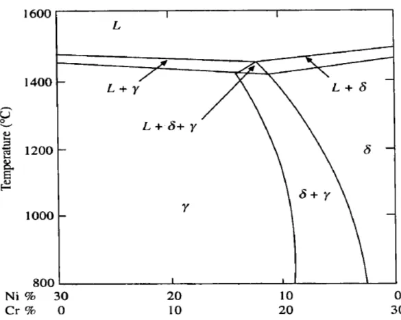
improve the corrosion resistance while chromium significantly improve the corrosion resistance of the steel. Type 304 austenitic stainless steel have face-centered cubic (fcc) crystal structure, and are well known for their good mechanical properties and corrosion resistance characteristic and high ultimate tensile strength (3). This group of steel is characteristically non magnetic and non heat treatable.
Figure 2.1. Fe-Cr-Ni phase diagram for 70% Fe content.
2.2 Corrosion behaviors of austenitic stainless steels
Austenitic stainless steels are known have exception in corrosion resistances due its passive film. Nonetheless, the corrosion process still occurs in these materials even though in low intensity. These materials also are known severe due to corrosion processes in specific environment like in the sea shore vicinity. The popular type of corrosion that occur in austenitic stainless steels are uniform corrosion and localized corrosion
2.2.1 Uniform corrosion
The simplest form of corrosion is uniform corrosion. The term uniform corrosion is used describe the corrosion damage that proceeds in relatively uniform manner over the entire surface of an alloy. It is an even rate of metal loss over the exposed surface. It is characterized by a chemical or electrochemical reaction or metal loss due to chemical attack or dissolution that proceeds uniformly over the entire exposed surface. A schematic illustration of uniform corrosion is shown in Figure 2.2.
2.2.2. Pitting corrosion
Pitting corrosion is one form of localized corrosion. Pitting corrosion refers to the formation of microscopic holes/cavities on the surface of the metal/ alloys either due to direct corrosion of heterogeneities present on the surface or due to the localized damage in the passive film present on the surface. It is well known that pitting corrosion occurs on passivated surface that are protected by a thin oxide layer. The thickness of this layer ranges from a monolayer to few nanometer (4,5). Under the influence of aggressive anions such as halide, localized attack take place on the passivated surface causing formation of holes that called pit. The pitting corrosion diagram on the metal alloys is shown in the Figure 2.3. Here a metal alloys is being pitted by an aerated sodium chloride solution. Rapid dissolution occurs within the pit, while the oxygen reduction takes place on adjacent surfaces. This process is self-simulating and self-propagating. Copious anodic productions of positively charged M2+ attract negative anions, e.g., Cl¯, to the initiation site to maintain electroneutrality. Thus, in the pit there is a high concentration of M3+ and Cl¯, as a result of hydrolysis a high concentration of hydrogen ions.
Air O2
O2 Na
Na Cl
Figure 2.3. Schematic of pitting corrosion in the metallic material
Both hydrogen and chloride ions stimulate the dissolution of most metals and alloys, and the entire process accelerates with time. Science the solubility of oxygen is
virtually zero in the concentrated solution, no oxygen reduction occurs within a pit. The cathodic oxygen reduction on the surfaces adjacent to pits tends to suppress corrosion. The hydrolysis processes can be expressed as:
M3+ + 3H2O + 3Cl¯ M(OH)3 + 3HCl
2.3 Mechanical treatments
The mechanism of mechanical surface treatment is based on the elastic–plastic cold working of the surface. In the recent literature, the main purpose of mechanical surface treatment is to improve mechanical properties of metallic materials. There are kinds of mechanical surface treatment like rolling, surface mechanical attrition treatment (SMAT), sandblasting, and shot peening. Shot peening is the popular technique that have been used in the industries compare than other techniques.
2.3.1 Shot peening
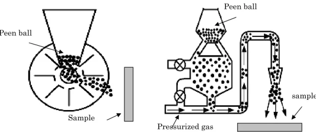
Shot peening is a kind of method for modify the surface of metallic materials. Shot peening involves projection of fine shots which could be made of steels, cast iron or glass, against the surface of the material at high velocity (6). The major application of shot peening is to increase the fatigue life of metal part by producing a uniform compressive stress in the surface layer. Shot peening may also be used as a metal forming process and its application ranges from small to large complicated and irregular shaped parts (7). Tao et. al. also reported that shot peening generated nanocrystalline on the surface of iron (8). They found that the grain size on the sample surface, treated 450 seconds and 250 seconds, reached 16 nm and 10 nm respectively. There are two basic techniques that were used in shot peeening processes for generating the energy. The first technique is employing pressurized gas and the second technique is employing the rotating well as shown in Figure 2.4. The impact energy of the shot causes plastic deformation of the surface and the subsurface of the sample.
(a) (b) sample Peen ball Pressurized gas Sample Peen ball
Figure 2.4. Shot peening process diagram (a) rotating well method (b) pressurized gas method
2.4 Chemical treatment
The chemical treatment provides an improvement of the surface properties on the post steel production. The basic principle of chemical treatment is employ chemical which are usually acid solution like H2SO4, HNO3, and HF to improve the
surface properties. During the treatment, the contamination on the metal surface is dissolved (9) and thicker oxide film is generated (10). The chemical treatments also perform in the post manufacturing processes. It well known that in the manufacturing processes cold work is performed and usually produces contamination and harm the passive film as well. Hence, in order to clean the surface and restore the performances of this metallic material chemical treatment is performed.
Figure 2.5. shows isocorrosion chart for type 18-8 stainless steel in nitric acid. The chart shows that 18-8 stainless steel exhibits low corrosion processes in the range temperature 50°F (10°C) up to 200°F (93°C) with nitric acid concentration between 0 up to 60% strength (%volume) (11). Hence, the passivation treatment with HNO3
Low corrosion rate area
Figure 2.5. Corrosion diagram of 18-8 stainless steel in HNO3 solution
2.5 Analytical method in corrosion
In order to understand the mechanism of corrosion, solve the corrosion problems encountered in the service condition, and improve the corrosion resistance of commonly used material as well as material of the future, the use of surface analytical and electrochemical technique is essential.
2.5.1 Potentiodynamic Polarization
Potentiodynamic polarization test provides rapid method in obtaining corrosion behavior of metallic material in a particular environment. The measurement takes only a short time (an hour at most). Potentiodynamic polarization over a short potential range about ±200 – 250 mV from the open circuit potential result provided the rates of other anodic reaction data. Potentiodynamic polarization over a wide range of potential generates more information about the system than just the corrosion rate. For instance, information can be obtained about the proximity of the natural potential to regions of passivity or localized corrosion susceptibility.
( + ) 2
E B
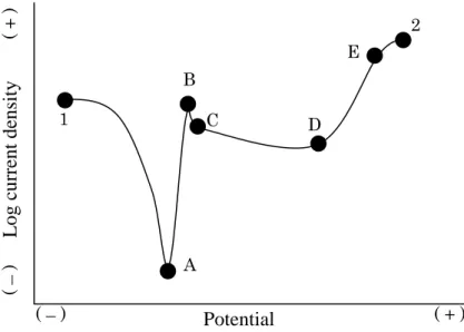
Figure 2.6. Diagram of anodic scan of potentiodynamic polarization
As can be seen in the figure, the scan starts from point 1 and progresses in the positive (potential) direction until termination at point 2. There are a number of notable feature on the curve. The open circuit or rest potential or natural potential is located at point A. At this potential the sum of the anodic and cathodic reaction rates on the electrode surface is zero. As a result, the measured current will be close to zero. This is due to the fact that the potentiostat only measures the current which it must apply to achieve the desired level of polarization. As the potential increase, we move in to region A-B, which is the active region. In this region, metal oxidation is the dominant reaction taking place. Point B is known as the passivation potential, and as the applied potential increase above this value the current density is seen to decrease with increasing potential (region B-C) until a low, passive current density is achieved (region C-D). When the potential reached a sufficiently positive value (point D, sometimes termed the breakdown potential) the applied current rapidly increases (region E).This increase may due to a number of phenomena, depending on the alloy and environment. For some system like aluminum alloys in sea water, increase in current may be pitting corrosion.
Log current density
2.5.2 Electrochemical Impedance Spectroscopy
Electrochemical impedance spectroscopy (EIS) is a non-destructive method that provides a powerful technique for analyze the surface character of metallic material in the particular environment. The EIS not only provide corrosion behavior data, but also the possibility process during measurement processes. The basic mechanism of EIS is applying small amplitude sinusoidal excitation signal to the system under investigation and measure the response (current and voltage). The excitation signal, expressed as function of time, has the form:
t EEt 0sin (2.1)
WhereEtis the potential at time , t E0is the amplitude of the signal, and is the radial frequency. In a linear system, the response signal, It, is shifted in phase
and has a difference amplitude than I0. It can be expressed:
I tIt 0sin (2.2)
An expression analogous to Ohm’s law allows us to calculate the impedance of the system as:
t I t E I E Z t t sin sin 0 0 (2.3)
t t Z Z sin sin 0 (2.4)The impedance is therefore expressed in term of a magnitude ( ) and a phase shift (
0
Z
). With Euler relationship
cos sinIt is possible to express the impedance as a complex function. The potential and the current can be describe as equation 2.6 and equation 2.7 respectively,
j t E Et 0exp
(2.6)
I j t It 0exp (2.7)Hence, the impedance is represented as complex number,
Z0exp
j Z0
cos jsin
Z (2.8)
Where, Z0cos is the real part
ReZ
of the impedance and jZ0sin is the imaginary part
ImZ
and j 1. The plot of the real part of impedance against the imaginary part gives a Nyquist Plot, as shown in Figure 2.7. The advantage of Nyquist representation is that gives a quick overview of the data and one make some qualitative interpretation. Re Z″ (–) (+) (+) – im Z ″ (– )Figure 2.7. Nyquist plot of Electrochemical Impedance spectroscopy.
2.5.3 Surface potential distribution
2.5.3.1 Contact Potential
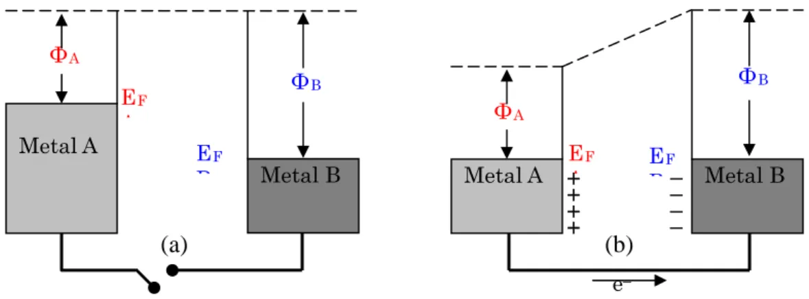
Contact potential is defined as the potential difference that arises at the junction of two dissimilar conducting materials. When two materials with different work function (Φ) are brought into contact with each other, electron will flow from the material that has a lower work function (higher Fermi energy, EF) to the material
with a higher work function (lower Fermi energy). This flow of electrons takes place until the Fermi energies of both materials become equal. This process is shown in Figure 2.8.
(a) (b)
Figure 2.8. Energy diagram of the Fermi equilibrium model of dissimilar metal (a) disconnected and (b) connected
Metal A has higher Fermi energy (EFA) than does metal B (EFB) (Figure
2.8a). Hence it is easier to remove an electron from metal A. When metal A and metal B placed in contact (Figure 2.8b), the electron flow from the metal A into metal B occurs, until the Fermi energy is the same on either side of the boundary. This produces a net negative charge on the metal B and a net positive charge on the metal A. If the metal plates are parallel, the two plates will behave like a parallel plate capacitor, in which the charge on each plate is proportional to the potential and can be describe by:
C Q
V (2.9)
WhereV is the potential between two plates, Qis the charge on the metal plates,
and is the capacitance of the dielectric material separating the plates. The capacitance of capacitor in parallel conductive plate can be expressed as:
C D A C 0 [F] (2.10)
Where, A is the area of the each metal plate, 0is the electric permittivity of vacuum and is the relative eclectic permittivity of the material between the electrode. The exchange of the electrons is time dependent. Hence, the current also depend on time and can be expressed:
t Q t I ) ( (2.11) t V C t C V ) t I ( (2.12) 2.5.3.2 Kelvin Probe
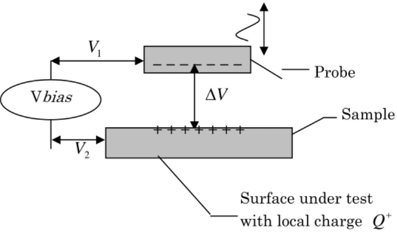
The schematic diagram of the Kelvin probe is shown in Figure 2.9. In the Kelvin probe the probe is vibrating relative to the sample.
Figure 2.9. Diagram of the vibrating Kelvin probe
The voltage correspond to the difference of potential between the probe and the ground reference and is the voltage between the charge plane of tested surface and
1 V 2 V _ _ _ _ _ _ _ 1 V Probe V Vbias Sample 2 V
ground. As the probe vibrates, a current induced by the vibration move between the prom and the sample via electronic connection.
By assuming constant experiment condition, the potential difference remains constant. As the result: 0 t V (2.13)
Hence, equation 2.12 can be simplified in the form equation 2.14.
t C V t I ) ( (2.14)
The varying capacitance is result of the vibration of the probe. The vibration is controlled and its distance movement can be describing as a sinusoidal.
t D D
D 0 1sin (2.15)
Where, is the average distance between the probe and the sample, is the amplitude of the vibration and
0
D D1
is the frequency of vibration. Hence, the current flow can be described as:
2 0 0 ) sin ( cos ) ( t D D t AD V t I (2.16)
In order to obtain contact potential (V) in the system, an adjustable potential source is added to the circuit and can be expressed:
Where, is the potential source added to the circuit, usually named as Bias Potential. The voltage source is adjusted until there is no current flowing between the probe and the sample
s V
Reference:
1. H.S. Khatak and B Raj, Corrosion of Austenitic Stainless Steel, Alpha Science, 2002.
2. ASTM Speciality Handbook : Stainless steel, 1994
3. M. McGuire, Stainless Steel for Design Engineering, ASM International, 2008. 4. A.I. Munoz and L.C. Julian, Electrochemica Acta, Vol. 55, p. 4428, 2010.
5. S. Fujimoto, S. kawachi, T. Nishio, T. Shibata, Electroanalytical Chemistry, Vol. 473, p. 265, 1999.
6. G. E. Dieter, Mechanical Metallurgy, McGraw-Hill International, 1988. 7. V. Schulze, Modern Mechanical Surface Treatment, Wiley-VCH, 2004.
8. N.R. Tao, M.L. Sui, J. Lu, and K. Lu, Nanostructured Material, Vol. 11, p. 433, 1998.
9. A.H. Tuthill and R. E. Avery, Advanced Material Processes, Vol. 6, p. 142, 1992. 10. L. Wegrelius, F Falkenberg, and I, Olefjord, Journal of Electrochemical Society,
Vol. 146, p. 1397, 1999.8.
11. M. G. Fontana, Corrosion Engineering, McGraw-Hill International, 1987. 12. P. Marchus and F Mansfeld, Analytical Methods in Corrosion Science and
Engineerig, Taylor & Francis, 2006.
CHAPTER THREE
APARATUSSES AND EXPERIMENTAL METHODS
3.1 Material
Type 304 stainless steel is used as the material in this work. The chemical composition of the sample can be found in chapter 4, 5, and 6. Prior to the treatment processes, the samples are polished with emery paper up to number 1000. The samples are then rinsed using distilled water and ethanol. The procedure of sample preparation for electrochemical and optical observation can be found in chapter 4, 5, and 6. The test solution and the treatment solution is prepared using laboratories grade chemical compound.
3.2 Shot peening
Shot peening processes are performed in Nagoya Institute of Technology using SFK-2 Fuji blaster. The detailed processes are mentioned in chapter 4.
3.3 Chemical treatment
The detail of chemical treatment method that has been used in this study can be found in the chapter 6.
3.4 Electrochemical measurement
3.4.1 Potentiodynamic polarization and electrochemical impedance spectroscopy
The samples are mounted with cooper wire and are covered using epoxy resin. The back side is kept open approximately 1 cm2 as observed area. Platinum is used as a counter electrode while Ag/AgCl/KCl is used as a reference electrode. The salt bridge, the connector between the sample and the reference, is made from KCl. The samples are measured in the 3.5% wt NaCl.
(a) (b) FREQUENCY ANALYZER Working electrode Counter electrode Salt bridge Reference electrode Salt bridge
Figure 3.1. Experiment set up diagram (a) Potentiodynamic polarization (b) Electrochemical impedance spectroscopy.
NS FRA 5022
Hakuto denko HS-5000
3.4.2 Open circuit observation
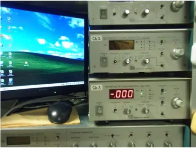
OCP observation is conducted using Hakuto Denko Potentiostat/Galvanostat HA-151 and Ag/AgCl/KCl is used as a reference electrode. The samples is immerse in the 3.5% wt at the specific time range until show significant potential changes. The device is shown in Figure 3.3.
Figure 3.3. Device set up for open circuit measurement.
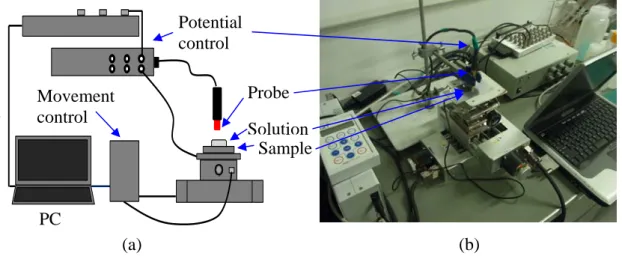
3.4.3 Surface potential distribution
Surface potential observation is conducted using custom built surface potential distribution device. The device work based on the Kelvin probe principle. The diagram of the experiment set up and the device are shown in Figure 3.4.
3.5 Surface morphology observation
Potential control
`
(a) (b)
Figure 3.4. Surface potential distribution analyzer (a) schematic diagram (b) device set up.
(a) (b)
CHAPTER FOUR
EFFECT OF MECHANICAL TREATMENT ON THE
CORROSION BEHAVIOR OF TYPE 304 STAINLESS STEEL
4.1 Introduction
Austenitic stainless steels are nonheat treatable alloys. Improving properties of austenitic stainless steels could be done by alloying stainless steel with other element (nickel, chromium, and molybdenum), implantation, sputtering, etc. However, these methods are expensive and inappropriate if in the utilization required materials with better properties with its original chemical composition. In the other hand, mechanical surface treatments provide improvements on the mechanical properties of metallic material. One of mechanical surface treatments is shot peening. The mechanism of shot peening is bombarding the surface sample with peening ball repeatedly. These processes eventually generate grain refinement on the surface and sub-surface of the treated substrate. This method is a common treatment process that have been applied in the metallic materials due to simple, low cost and did not change their chemical composition in addition of its versatility in enhancing mechanical properties of metallic materials (1, 2, 3). Although the chemical composition of the substrate does not affect, but the electrochemical properties of the material are suspected change by this process due to the modification of the material surface (4, 5, 6, 7).
general/uniform corrosion, the passive state with immunity to corrosion, and transpassive with severe corrosion process. In terms of stainless steels, the passive state and pitting potential have more attention because stainless steels have an exception in uniform corrosion due to existences the passive film on its surface, however, weak in localized corrosion like pitting corrosion. It is caused by the outbreak of passive film by chloride ion. Hence, understanding the characters of the passive film of metallic material is a basic part to improve their ability of stainless steel to against corrosion, particularly localized corrosion.
In order to characterize the passive film and surface barrier characters of the metallic materials, electrochemical impedance spectroscopy (EIS) provides an advanced method. The EIS attract much attention due to provide a non-destructive test to study the passive film. Moreover, the EIS also proposes to examine the phenomena at the interface of metal/passive film, the passive film/ solution (electrolyte), and at inner passive film. In general, the EIS data is interpreted in Nyquist plot. Furthermore, the physical model of the EIS with an equivalent circuit provides a deeper analysis. The equivalent circuits are the electronic circuit model that used to describe the phenomena that occur at the metal surface.
The aim of this work is to investigate the effect of mechanical surface treatment on corrosion behavior of austenitic stainless steel. The type 304 stainless steel is used in this work due to type 304 stainless steel is the most popular of type stainless steels that have been used in the industry.
4.2 Experimental method 4.2.1 Material
carbide precipitation. After shot peening processes, the sample was mounted with copper wire and covered with epoxy resin with the open area of 10 by 10 mm.
Table 4.1
Chemical composition of type 304 stainless steel in wt %
Alloys C Si Mn P S Ni Cr Fe
Type 304 0.07 0.46 0.84 0.028 0.007 8.04 18.06 Balance
4.2.2 Electrochemical observation
The potentiodynamic polarizations and EIS were performed using a three-electrode arrangement. These tests were used HZ-5000 potensiostat as the devices. These tests were performed in 3.5 %wt NaCl at room temperature using Ag/AgCl/KCl (sat.) as reference electrode and Pt as counter electrode. The potentiodynamic polarization was traced by scanning potential region between -0.6 and 0.8 V under almost steady-state conditions (dE/dt = 1mVs-1). The EIS were measured in the frequency range between 30 mHz and 10 kHz at sinusoidal potential amplitude 5mV. The EIS measurements were conducted in the passive region of the samples as the results of potentiodynamic polarization. EIS analyzer program, Spectrum-Analyzer®, was used to verify the suitability of the equivalent circuit to the experimental data.
Prior to the potentiodynamic polarization and EIS test, the specimens manually rinsed using 99.5% pure ethanol. The ultrasonic cleaning using VS -70R ultrasonic bath cleaner also performed after manually rinsed to ensure the sample from impurities. In the post cleaning processes, the samples rinsed with pure distillate water and dried naturally in the atmospheric environment. The sodium chloride solution (NaCl solution) was prepared from laboratory standard NaCl and pure distillate water.
4.3 Results and discussion 4.3.1 Grain refinements
Figure. 4.1 and Figure. 4.2 show cross section observation of untreated and treated type 304 respectively by optical microscope. The observation revealed grains size of untreated type 304 stainless steel approximately 100 µm as shown in Figure. 4.1. After treated by shot peening processes the grains were modified and the plastic deformations were formed on the sample as shown in Figure. 4.2. The deformed zone occurs on the surface and broad until beneath of the sample as shown by an arrow in Figure. 4.2. Moreover, at the surface sample approximately until 15 µm depths, there are layers that cannot be observed by an optical microscope. It may due to the grain refinement was formed, and the grains size approach nanometer-scale. In this size, optical microscope cannot be used due to over of its magnification ability. Therefore, the FE – SEM observations were conducted. FE – SEM result shows grains size approximately 1µm as shown in Figure. 4.3. The grains size of the type 304 stainless steel with shot peening processes decreases significantly around 100 times smaller than grains size of type 304 stainless steel without shot peening process.
The approximation mechanism of grain refinement grain refinement processes is proposed. Based on optical and FE–SEM observation as shown in Figure. 4.2 and Figure. 4.3, the grain refinement tending due to plastic deformation and mainly dominated by deformation twinning. This may attribute of the type 304 stainless steel has low stacking fault energy (8). The basic processes of grain refinement due to deformation twinning schematically can be illustrated in Figure. 4.4, and involves the following processes:
1. The formations of high-density parallel twins with a single direction. In this step, the large amount of twin boundaries starting forming and divide the original coarse grains into the lamellar twin block as shown in Figure. 4.4a. 2. The formation of the secondary twin with different orientation as shown in
3. The formations of randomly oriented grains as shown in Figure. 4.4c. This process needs substantial variation of miss orientations in the neighboring sub grains.
Figure. 4.1. Optical observation of untreated type 304 stainless steel
Figure. 4.3. FE-SEM observation of treated type 304 stainless steel.
Figure. 4.4. Schematic illustration of grain refinement of type 304 stainlesss steel due to shot peening (a) parallel twin (b) secondary twin (c) randomly oriented grains.
4.3.2 Active-passive behavior of the treated samples in 3.5 %wt NaCl
However, the samples show different value of breakdown potential and broaden the range of passive potential.
Figure. 4.5. Potentiodynamic polarization curve of type 304 stainless steel in 3.5 %wt NaCl solution
The passive region of untreated type 304 stainless steel broad in range approximately from -0.2 V to 0.3 V. Meanwhile, the passive film region of treated sample expanded approximately 60 %, there is from -0.3 V to 0.5 V. The well defined pitting potentials also obtained. The breakdown potential of type 304 stainless steel, indicating localized corrosion potential, and shift to more noble after shot peening processes. The potential shifts from 0.3 V to 0.5 . Hence, it can be inferred that the shot peening processes improve the passive film properties and localized corrosion resistance.
4.3.3 Surface barriers character of the treated sample at various passive potential
polarization results. This also can be used to represent the passive film properties that formed on the sample surface at passive range. The data were presented in Nyquist plots as shown in Figure. 4.6. The Nyquist plotted with normalized real impedance
Z and imaginary impedance Z show depressed semicircle instead of perfect
semicircle in both samples, untreated and treated samples. The impedance resistance, indicated by the diameter of the curve, of treated and untreated type 304 stainless steel shows similar character where the impedance resistances of them increase with passive potential. However, the impedance resistance of the treated type 304 stainless steel higher than untreated sample in same passive potential value in all tested potential. It indicated that the shot peening processes improved the surface barrier of type 304 stainless steel in the broad passive range.
-0.1 V 0 V
2 V 1 V
Moreover, the imaginary part of Nyquist plot in Figure. 4.6 shows high capacitive response. It is supporting the assumption there are passive films present on the surface of the sample. Previous study revealed that the passive film of metallic materials has capacitive character (10, 11). Hence, the improvement of surface barrier on the type 304 stainless steel may attribute of better passive film properties after shot peening process treated this sample. Hence, the possibility physical illustration of passive film of the type 304 stainless steel before and after treated by shot peening processes is shown in Figure. 4.7.
Figure. 4.7. Schematic illustration of type 304 stainless steel (a) Before treated by shot peening (b) After treated by shot peening
The physical model with an equivalent circuit is proposed to explain the process on the surface sample. This work adopted equivalent circuit consisting on a solution resistance and two parallel resistance-capacitance combinations. The solution resistance is represented by . The impedance in the inner of passive film is represented by consist of (passive film resistance rate) and (passive film admittance). The was used instead of an ideal capacitor due to the passive film of metallic materials has no ideal capacitor character. This behavior may due to inhomogeneities in the passive film (12). Meanwhile, the impedance in the boundary passive film/solution and metal/passive film is represented by consist of charge transfer resistance and double layer capacitance . The and have correlation with the active surface area. The active surface areas increase if the
boundary between passive film/solution and metal/passive film increasing. In order to get a clear analysis, the circuit model is divided in two parts (passive film resistance and charge transfer resistance) and then combines into one equivalent circuit model.
The first part of the circuit model is associated with the impedance in the passive filmZf and the physical illustrations are shown in Figure. 4.8.
(a) (b)
Figure 4.8 Equivalent circuit model of passive film resistance (a) Before treated by shot peening (b) After treated by shot peening
The passive film is assumed had defect sites on its surface even before chloride ion penetration. Hence, the impedance in the passive film consists of impedance without defect Z and impedance with defectf Z as shown in equation f
4.1.
f f
f Z Z
Z (4.1)
Meanwhile, the impedance of the passive film Zf is the sum of Z and f
. The consist of passive film resistance without defect and passive film admittance without defect
f
Z Z f Rf
E
CP as shown in equation 4.2. Meanwhile, consists of passive film resistance with defect
f Z f
R and passive film admittance with defect
is shown in equation 4.3.
f R CPE f Z Z Z 1 1 1 (4.2) f R CPE f Z Z Z 1 1 1 (4.3)
The value of is affected by thickness of passive film. Thick passive film provides higher resistance. Hence, due
f R
f
R represent thick passive film and R f
represent thin passive film the value of R higher thanf . This correlation reversely applies for value. The thicker passive film provides lowCPE value. Meanwhile, low value provides high . Hence, it can be inferred that value is higher than due to the passive film is thicker and as mathematically is represented by equation 4.4. Therefore, with fewer defects, the passive film has higher passive film impedance resistance.
f R CPE Z CPE ZCPE f Z f f f Z Z (4.4)
Meanwhile, after treated by shot peening processes the smaller grains were formed in the surface and subsurface of type 304 stainless steel. In the previous finding, the passive film formed easier in small grain (13, 14). Due to passive film is easier formed in the smaller grain, may the defect in the passive film of type 304 stainless steel can be minimized after shot peening treatment were conducted. Thereby, the passive film impedance resistances of the treated type 304 stainless steel may better than untreated 304 stainless steel, and can be expressed in equation (4.5).
) ( ) (treated Z untreated Zf f (4.5)
The second part of the circuit model is the interface activity of film/solution and metal/film, and represented by double layer capacitance and charge transfer resistance . In the further immersion in the solution that containing chloride ion, in
dl C ct
addition of original defect, the secondary defects are formed in the passive film of type 304 stainless steel due to chloride ion penetration. The physical illustration of the chloride penetration in the passive film with electrical circuit is shown in Figure. 4.9. The increments of defect generate increments of active surface area. In the other hand, the treated type 304 stainless steel may has better ability healing the defect due to has smaller grains in the its surface. Moreover, smaller grains may form chromium-enriched passive film which has better properties (15). Thereby, type 304 stainless steel may has a passive film with less defects and chromium-enriched character after treated by shot peening processes.
(b) (a)
Figure 4.9 Equivalent circuit model of charge transfer resistance (a) Before treated by shot peening (b) After treated by shot peening
D A C dl dl 0 (4.7) dl C A J D Z dl 0 (4.8)
Where 0 and is the permittivity of vacuum and the relative permittivity
of the solution respectively, which are constant. Meanwhile, is the distance of positive and negative charge and is the double layer area (active area). The is assumed constant due to the interface between solution/passive film and passive film/metal distance is not affected. Hence, the factor that affects the impedance of double layer capacitance is the active area of the samples. The impedance double layer capacitance increase when the active area decrease. Meanwhile, the defect in the passive film type 304 stainless steel may be reduced by shot peening process. With fewer defects on the passive film, the sample provides reduced the number active area . Hence, the double layer capacitance impedance of the type 304 stainless steel increasing after treated by shot peening process due to less active area .
D dl A dl D dl C Z Z dl dl A dl C A dl A dl C Z A
The impedance of charge transfer resistance can be expressed by charge transfer resistance impedance . The is affected by the properties of the passive film. The passive film with chromium-enriched may improve the ion transfer barrier from metal to the solution. Hence, the treated sample is suspected has higher charge transfer resistance .
ct R ct R Z ct R Z ct R Z
The impedance of film/solution and metal/film boundary interface is the sum of double layer capacitance impedance and charge transfer resistance impedance and can be expressed as:
As mentioned in previous discussion that impedance value of double layer capacitance and charge transfer resistance of treated sample higher than untreated sample and it can be inferred that value of boundary impedance of treated sample higher than untreated sample. It correlation can be expressed as:
) (
)
(treated Z untreated
Zb b (4.10)
The total impedance of the system is the sum of impedance of solution resistance , impedance of passive film , and the impedance of the boundary interface . It can be expressed by equation (4.11) and (4.12).
Rs Z b Z f Z barrier film passive solution total Z Z Z Z (4.11) ct dl f C R R CPE Rs total Z Z Z Z / / (4.12)
Thereby, base on equation 4.10 and 4.12 the total value of impedance resistance of the treated sample higher that the untreated sample. It can be interpreted in equation 4.11. ) ( ) (treated Z untreated Ztotal total (4.11)
Based on equation 4.12, total impedance of the system can be interpreted in an equivalent circuit as shown in Figure. 4.10.
Moreover, the fitting is conducted to ensure that the equivalent circuit approximation is appropriate to explain the physical processes. The results show the fitting curve close to experiment data as shown in Figure. 4.11.It can be inferred that the equivalent circuit may be able to be used to describe the processes in the surface of the type 304 stainless steel in 3.5 %wt NaCl solution.
Figure 4.11. The fitting of simulation data on the experiment data base on proposed equivalent circuit
4.4. Conclusion
The electrochemical behaviors and microstructures of shot peened type 304 stainless were revealed in this work. The observation results lead to the following conclusion:
Passive potential of the treated type 304 stainless steel expanded and the pitting potential shift to more noble. It may caused by better passive film properties with less defect that formed on the sample.
Surface barrier observation by EIS shows that the impedance resistance is influenced by capacitance responses indicate that the passive film play role in the improvement of the surface barrier to against corrosion processes.
References
1. S.B. Fard and M. Guaglino, Fracture and Structural Integrity, Vol. 7, p. 3, 2009. 2. N.R. Tao, M.L. Sui, J. Lu, and K. Lu, Vol. 11,Nano Structure Material
p. 443, 1999.
3. G. Liu, J. Lu, and K. Lu, Material Science & Engineering A, Vol. 286, p. 91, 2000. 4. D.H. Hur, M.S. Choi, D.H. Lee, M.H. Song, S.J. Kim, J.H. Han, Nuclear
Engineering and Design, Vol. 227, p. 155, 2004.
5. T. Wang, J. Yu, and B. Dong, Surface & Coatings Technology, Vol. 200, p. 4777, 2006.
6. M. Mhaede, F. Pastorek, and B Hadzima, Materials Science & Engineering C, Vol. 29, p. 330, 2014.
7. V. Azar, B. Mashemi, and M.R. Yazdi, Surface & Coatings Technology, Vol 204, p. 3546, 2010.
8. B. Bay, N. Hansen, D.A. Hughes, and D. Kuhlmann-Wilsdorf, Acta Metallurgica Materialia, Vol. 40, p. 205, 1992.
9. H.W. Zhang, Z.K. Hei, G. Liu, J. Lu, and K. Lu, Acta Materialia., Vol. 51, p. 1871, 2002.
10. M. Serdar, L.V. Zulj, and D. Bjegovic, Corosion Science, Vol. 69, p. 149, 2013.
11. A.K. Sukla, R. Balasubramaniam, and S. Bhargava, Intermetallics, Vol. 13, p. 631, 2005.
12. R.M., Caranzanza and M.G. Alvarez, Corrosion Science, Vol. 38, p. 909, 1996.
13. K.D. Ralston, D. Fabijanic, and N. Birbilis, Electrochimica Acta, Vol. 56, p. 1729, 2011.
14. G. Meng, L. Wei, T. Zhang, and F. Wang, C. Dong, X. Li, Corrosion Science, Vol. 51, p. 2151, 2009.
CHAPTER FIVE
ATMOSPHERIC CORROSION BEHAVIOR MECHANICALLY
TREATED TYPE 304 STAINLESS STEEL
5.1 Introduction
Stainless steel gets much consideration due to their exception in general corrosion resistance, however has a weakness regarding localized corrosion. The stainless steel is susceptible to pitting corrosion in the seashore vicinity. This corrosion caused by chloride ions that generate the passive film breakdown. The chloride ions come from salt in the atmosphere. The salt vapor or mist in the air formed from the evaporating sea water and then condense on the surface of stainless steel and then form salt solution droplets when the pH rise and/or the temperature drop. Inversely, this droplet evaporates when the temperature increase and/or the relative humidity decrease causing the chloride ions concentration increasing. It well known that at specific chloride concentration localized corrosion could be generated. In the previous work, Tsutumi et al. (1) and Noda et al. (2) has reported that in 40% relative humidity, MgCl2 generate localized corrosion in the metallic material.
The study of the corrosion behavior of type 304 stainless steel after treated by shot peening process in submerged solution was conducted (7). In advance, to understand the corrosion properties of the shot peening material in another environment condition, like in the atmospheric environment, further study need to be conducted. However, the study of the corrosion behavior of metallic materials in the atmospheric environment is difficult to be conducted because the conventional electrochemical measurement, like potentiodynamic polarization, cannot be used. Unlike conventional electrochemical measurement which all of the substrate submerged in the electrolyte solution, the electrolyte on the atmospheric corrosion is limited and only thin over the sample. In order to resolve the limitation of conventional electrochemical measurement method in the atmospheric environment, a surface potential distribution method that based on the Kelvin probe was applied in this study. The device has a similar mechanism to the Kelvin probe that is the non-contact method. This method allows evaluating the potential of the surface sample without touching the surface sample and also the electrolyte. This method had been used to measure the corrosion properties of the metallic material and evidently succeed (8, 9, 10).
In this study, the effect of shot peening process on the atmospheric corrosion behavior of type 304 stainless steel was observed. MgCl2 solution droplet was used as
the artificial thin electrolite that attach on the surface of the sample.
5.2 Experimental method 5.2.1 Sample preparation
treated using shot peening treatment is shown in Figure 5.1. The shot peening process was implemented in 4 minutes at 25°C.
Treated side Untreated side
Figure 5.1. Schematic illustration of shot peened sample
5.2.2 Surface potential measurements
The surface potential measurement was conducted using a custom-build device which the schematic diagram of the test setup is shown in Figure 5.2. The basic mechanism of this technique is measuring the potential of the surface sample based on the capacitance of the surface sample. This method is convenient for observing the atmospheric corrosion since conventional electrochemical measurement method hard to be carried due to limited in electrolyte on the sample surface. Platinum (Pt) was used as the calibrator of the surface potential analyzer and calibration process was carried prior to the measurement.
In this study, MgCl2 solution was used as the electrolyte droplet which is
placed on the sample surface due to its deliquescence in the atmospheric environment (1, 2). This solution was prepared from reagent grade chemical MgCl2 and pure
distilled water. The MgCl2 droplets with concentration 54 mM were placed on the
surface sample using micro syringe. There are three sides of the sample that were placed by MgCl2 solution, the treated side, intersection side, and untreated side as
shown in Figure 5.3. This measurement was conducted at 25°C with 40% RH. The scanning processes were conducted in 40 by 40 mm of area, 250 of line, 250 of point data/ line, and 6.6 s/ line of scanning speed. The schematic diagram of scanning area is showed in the Figure 5.4. Prior to measurement processes, the sample has been rinsed using 99% pure ethanol to ensure the sample is clean from impurities.
5.2.3 Corroded surface observation
To generate pitting corrosion, the samples with MgCl2 droplet on its surface
droplet average diameter was 5 mm as shown in Figure 5.5. The PME3 Olympus optical microscope was performed to visualize the surface morphology of the corrosion product. probe Sample Calibrator (Pt) potential analizer mat x y
Figure 5.2. Schematic diagram of surface potential measurement device.
Intersection side
Treated side Untreated side
MgCl2droplet
Figure 5.3. Schematic diagram of MgCl2 droplet on the sample surface for
surface potential distribution observation.
Figure 5.4. Schematic diagram of scanning point and area.
Box Rh 40% Temp 25ºC 5 mm Droplet Specimen Humidity meter
Figure 5.5. Schematic diagram of corroded surface observation.
5.3 Result
5.3.1 Surface potential distribution
The surface potential distribution of type 304 stainless steel with electrolyte droplet on its surface is shown in Figure 5.6. The shot peening process evidently shifts the surface potential to nobler which is indicated by surface potential increament of the treated sample.
The potential distribution of the untreated sample consists of four parts when when exposed under MgCl2 droplet. It is indicated by four different colors, black,
dark blue, medium blue and light blue. However, the potential area of the treated sample only consists of two parts that are light blue and ultra light blue. At the intersection side can be observed that the potential consists of three parts that are dark blue, medium blue, and light blue. The differences potential distribution indicates deference electrochemistry behavior between untreated, treated sample and in the intersection side. The observation also revealed that the potential of the untreated and treated sample decreasing at 110 minutes testing time and gradually increase for further testing time.
5.3.2 Profile of corroded surface
The optical observation of the morphology of the corroded site of type 304 stainless steel under MgCl2 electrolyte droplet is shown in Figure 5.7 and Figure 5.8.
a b
Figure 5.6. Surface potential distribution of untreated and shot peened type 304 stainless steel with MgCl2 droplet (a) 55 minutes (b) 110 minutes (c) 160 minutes (d)
210 minutes (e) 265 minutes
c d
Treated Untreated
e
Treated Untreated Treated Untreated
1 2
3
a
b
a
b
The anode area is all area inside dashed circle 2. Meanwhile, the green-blue circle area is associated with cathode area. This area is among dashed circle 2 and dashed circle 3. The green-blue color was formed from the corrosion product of type 304 stainless steel that deposited in the cathode area. In the center of the anode area, there are two holes with size approximately 50 μm as indicated by dashed circle 1. The holes are predicted as the starting points of the pitting corrosion. However, this circular pattern and hole are not found in the treated sample. The rust in the treated sample spread uniformly as shown in Figure 5.8.a and Figure 5.8.b. In the case of the intersection side, the pattern cannot be observed, although the small hole can be seen as shown Figure 5.7.b.
5.4. Discussion
The correlation between corrosion potential and the surface potential has been reported in a previous finding (11). The corrosion resistance is enhanced if the surface potential shifts to more positive value (noble).
The effects of shot peening in the corrosion resistances of type 304 stainless steel with MgCl2 electrolyte droplet were revealed in this study. The corrosion
resistance of type 304 stainless steel after shot peening process was enhanced. This enhancement may have a correlation with the good passive film properties after type 304 stainless steel was treated by shot peening.
In the presence of MgCl2 droplet solution, the galvanic cell is formed in the
untreated and treated type 304 stainless steel. The MgCl2 droplet has a function as a
salt bridge in the corrosion reaction. Hence the galvanic cell can be formed. The anode site is formed in the center of the droplet, and the cathode is formed in the around on the anode site. At the center of the MgCl2 droplet show the lowest surface
304 stainless higher than treated type 304 stainless steel. It may due to passive film that formed in the untreated sample weaker than the treated type 304 stainless steel.
The samples show that the surface potential decrement at 110 minutes time immersion and gradually increases. It may be due to oxidation processes occurring in both samples to produce oxide film. After oxide film is formed on its surface the potential slightly increases time by time. This process can be analogical as galvanic protection which there is oxide film formation then the passive film serve as barrier for further oxidation processes.
The corrosion product of the untreated and treated type 304 stainless steel after conducted under MgCl2 droplet in 24 hours was revealed by optical microscope in
this study. The corrosion sites of the untreated type 304 stainless steel in the presence of MgCl2 droplet consist of anode area, cathode area, and small hole inside the anode
area. This corrosion type is pitting corrosion. This finding agrees with the previous study (1). The pitting corrosion under chloride solution droplet takes place in the horizontal direction, unlike deep hollow pit type when immerses in the chloride solution. This difference of pit morphology is attributed to differences in the mass transport and effective cathode area (1). The MnS inclusion is inferred play role of the initiating processes of the pitting corrosion (1). The hole in the center of the anode area is the starting point of the pitting corrosion where the MnS has been there and initiate the pitting corrosion as well as previous finding (1). The localized corrosion that initiated by MnS occurs when the passive film and repassivation processes no longer able against the dissolution processes and chloride ion penetration. Hence, the MnS dissolve and generate pitting corrosion. In this study, the pitting corrosion occurs in the untreated type 304 stainless steel.
At the intersection site, the typical character of corrosion product like in the untreated sample was not observed. Although small pit was observed, but the cathode and anode pattern circle area was not formed. This pit may initiated by the grains defect in the intersection site vicinity. This defect may due to imperfectly shot peening process when approaching intersection site.
5.5 Conclusion
Based on the above results and discussion, the following conclusions are reached:
Both of treated and untreated sample shows local galvanic cell that indicated by the formation of anode and cathode area.
Surface potential value of the treated sample is increasing at anode and cathode area. It indicates that the corrosion resistance of the treated sample in atmospheric environment increases after treated by shot peening processes.
Surface potential value tends to decrease at early strep of observation processes and gradually increase at the further step. It may due to oxidation processes take palce early step and followed by oxide film formation which acts as oxidation barrier on the surface.
References
1. Y. Tsutumi, A. Nishikata, and T. Tsuru, Corrosion Science., Vol. 49, p. 1394, 2007.
2. K. Noda, M. Yamamoto, H. Masuda, and T. Kodama, in Evaluation of Atmospheric Corrosion on Low Alloy Steel under Seashore Environment, B. Hou, PV 2000-8, p.136, Marine Corrosion and Control, Beijing (2000).
3. D.H. Hur, M.S. Choi, D.H. Lee, M.H. Song, S.J. Kim, J.H. Han, Nuclear Engineering and Design, Vol. 227, p. 155, 2004.
4. T. Wang, J. Yu, and B. Dong, Surface & Coatings Technology, Vol. 200, p. 4777, 2006.
5. M. Mhaede, F. Pastorek, and B Hadzima, Materials Science & Engineering C, Vol. 29, p. 330, 2014.
6. V. Azar, B. Mashemi, and M.R. Yazdi, Surface & Coatings Technology, Vol 204, p. 3546, 2010.
7. T.D. Widodo and K. Noda, ECS Transaction, Vol.50, p. 273, 2013. 8. H. Masuda, Corrosion Science, Vol. 49, p. 120, 2007.
9. H. Masuda and H. Katayama, 208th Meeting of Electrochemcal Society, 2005. 10. A.P. Yadav, H. Katayama, K. Noda, H. Masuda, A. Nishikata, T. Tsuru,
Electrochemica Acta, Vol. 52, p. 3121, 2007.
CHAPTER SIX
CORROSION BEHAVIOR OF CHEMICALLY TREATED TYPE
304 STAINLESS STEEL IN SODIUM CHLORIDE SOLUTION
6.1. Introduction
Corrosion resistance is an essential part of metallic material properties especially in stainless steel. This behavior strongly depends on among parameters on the surface state. The most factor that affecting corrosion resistance in stainless steel is oxide film that formed on its surface. These films prevent metallic material from continuous oxidation processes. However, the passive film easily vanished due to stretch, metal working processes, and harsh environment.
It is known that HNO3 treatment is an effective method for cleaning metal
surface from metal working particle, oil dirt, and iron oxide that left on the metallic surface (1). In other hand, HNO3 treatment may able to increase corrosion resistances
of stainless steel. The author reported that the effect of chromium enrichment in the film formed by HNO3 treatment is an effective method for increasing corrosion
resistance of stainless steel (2, 3). Although treating stainless steel with HNO3
effective improve its corrosion resistances, but immerse stainless steel in the HNO3
solution also reported have possibility negative effect (4, 5, 6). Hence, appropriate treatment processes must be done properly to minimize residual effect from the treatment. Understanding the corrosion behavior of chemically treated stainless steel in the harsh environment provides an evaluation on the effectiveness of treatment processes. However, characterization of the treated material with electrochemical measurement in the harsh environment slightly revealed.
temperature and concentration of HNO3 solution on the effectiveness of the treatment
processes was also revealed in this work.
6.2 Experimental Method 6.2.1 Material
The chemical composition of type 304 stainless steel used in this study is shown in Table 6.1. The specimens with dimension of 10 mm x 10 mm x 1mm were cut and attach with cooper wire. The specimens then mounted with epoxy resin on its back surface and kept open on its front surface. The specimens then polished with 600 up to 1000 grit emery paper then the specimens were cleaned with distilled water and followed by high purity ethanol. Ultrasonic bath cleaning also performed to ensure the specimens clean from impurities. After ultrasonic bath cleaning, the specimens were rinsed in distilled water and use as samples for surface treatment.
Table 6.1 Chemical composition of type 304 stainless steel in wt %
Alloys C Si Mn P S Ni Cr Fe
Type 304 0.07 0.46 0.84 0.028 0.007 8.04 18.06 Balance
6.2.2 Chemical treatment
The surface of the samples was subjected to chemical treatment to improve its passive film. The chemical treatment was processed by HNO3 solution that was
prepared from laboratory grade chemical and high purity distilled water. In order to obtain the most effective treatment processes parameter, pre-chemical treatment processes were conducted on the samples prior to main treatment processes. The schematic diagram of pre-treatment and main treatment processes is shown in Figure 6.1 and Figure 6.2 respectively. During treatments processes the samples were immerse in the nitric acid solution with specific temperature and solution concentration. The solution was stirred with speed 100 Rpm. In the pre-chemical treatment, the samples were conducted in various concentrations of HNO3 solution
from 0.1 M, 1 M, 3 M, and 5 M HNO3 at three variable temperatures 30ºC, 50ºC
Thermometer
Reference Electrode
Figure 6.1 Schematic diagram of pre-treatment setup for obtaining optimal temperature and solution concentration parameter.
Figure 6.2 Schematic diagrams of main chemical treatment processes with optimal temperature and HNO3 concentration based on pre-treatment processes
Rinse in distilled water
Check the pH of the rinsing water
High pH Normal pH Used as a sample ºC Rpm Rotation
control Temperature control