Anode properties of thick-film electrodes prepared by
gas deposition of Ni-coated Si particles
Hiroyuki Usui, Masafumi Shibata, Koji Nakai, and Hiroki Sakaguchi*
Department of Chemistry and Biotechnology, Graduate School of Engineering, Tottori University 4-101 Minami, Koyama-cho, Tottori 680-8552, Japan
*Corresponding author. Tel./Fax: +81-857-31-5265; e-mail: [email protected]
Abstract
Thick-film electrodes of Si particles coated with Ni, Ni-Sn, and Ni-P were fabricated by electroless deposition followed by gas deposition to form the anode of a Li-ion battery. The electrode of Ni-coated Si showed remarkably improved cycling performance with a discharge capacity of 580 mA h g-1 at the 1000th cycle, which is possibly caused by its higher elastic modulus than that of the
uncoated Si electrode. The electrode of Si coated with Ni-P, which consisted of Ni3P, with the lower
coating amount exhibited a higher initial capacity and excellent cycling performance with a capacity of 790 mA h g-1 at the 1000th cycle, whereas poor performance was obtained for the electrode of Si coated with Ni-Sn. The excellent performance in the case of Ni-P coating is attributed to the smaller amount of coating, the high elastic modulus, and the lower reactivity of Ni3P with Li ions in
1. Introduction
Silicon is among the most promising materials for the anode of next-generation Li-ion batteries because the theoretical capacity of silicon (~4200 mA h g-1) is much larger than that of graphite (372
mA h g-1) in the anode of practically used batteries. Alloying and de-alloying reactions of Si with Li ions lead to this large capacity. However, as a critical problem, extensive pulverization of Si occurs as a result of the volumetric changes of Si during the reactions. The Si anode is degraded by this pulverization, resulting in increased irreversible capacity and reduced electrochemical performance in earlier charge–discharge cycles. When a silicide is used instead of elemental Si as the active material of the anode, the discharge capacity is drastically degraded, owing to the smaller storage amount of Li ions in the silicide. Therefore, we believe that anodes for next-generation Li-ion batteries should mainly consist of elemental Si to take an advantage of its larger theoretical capacity. Gas deposition (GD) is a suitable method for forming thick films. In this method, an aerosol consisting of raw particles and a carrier gas is sprayed near the speed of sound from a nozzle onto a substrate. For preparing electrodes, we have demonstrated that the GD method has various advantages including (i) the strong adhesion between the active material particles as well as between the particles and the substrate, (ii) the nearly unchanging composition in the thick film formed without atomization (e.g., vaporization) of the particles, and (iii) the formation of interstitial spaces between particles, which is a favorable structure to release the stress induced by the volumetric change of the active material particles [1]. Furthermore, we fabricated composite thick-film electrodes consisting of elemental Si particles and other materials, and have discovered that the electrode performance is remarkably improved by the synergetic effects of the properties of Si and the combined materials [1-5]. In particular, we have prepared thick-film electrodes consisting of Ru-coated Si [4] and Cu-coated Si [5] particles by electroless deposition (ELD), and found that these electrodes exhibited excellent cycling performances. The results indicated that the coated layers of Ru and Cu serve as a buffer layer to release the stress generated in Si particles during the
charge–discharge reactions, and that the electrode performance strongly depends on its mechanical properties, such as elastic modulus.
Nickel plating has been widely used for surface coating to enhance the durability of the base material. In particular, an ELD technique of Ni–P is a well-known commercial process because Ni–P coating can be applied in many fields because of its excellent properties of high corrosion resistance, high wear resistance, high hardness and acceptable ductility [5–8]. Coatings of Ni and its compounds on Si particles are expected to improve the mechanical durability of thick-film electrodes prepared by the GD method using the coated particles. In this study, we used the used the GD method to prepare thick-film electrodes, which consisted of Ni and its compounds (Ni-Sn, Ni-P) on Si particles; we then investigated the relationship between the mechanical properties and electrode performance of the electrodes.
2. Experimental
Ni-coating on Si was performed in 0.1 mol/L (M) H2SO4 aqueous solution containing Ni2+ ions
and commercial Si particles (Wako Pure Chemical Industries, Ltd., 99%, size distribution: 0.1~2 µm) by adding NaBH4. The detailed procedure has been described in previous papers [4, 5]. We also
used SnSO4 to form the stannide (Ni-Sn), and NaH2PO2•H2O and a reducing agent,
Na3C6H5O7•2H2O, to form the phosphide (Ni-P). All reagents were analytical grade and used without
further purification. The elemental analysis of the coated particles was carried out by energy dispersive X-ray analysis (EDX, EDS-54033MCK, JEOL Ltd.) and inductively coupled plasma atomic emission spectroscopy (ICP-AES, Spectro Ciros CCD, Rigaku Ltd.). The morphology and crystal structure of the particles were observed by transmission electron microscopy (TEM, JEOL-2010, JEOL Ltd.).
For gas deposition, Cu foil substrates with thickness of 20 µm were set up in a vacuum chamber with a guide tube [1-4]. An aerosol consisting of Ar gas (differential pressure: 7×10⁵ Pa) and active
material powders of the coated Si was generated in the guide tube, and sprayed from a nozzle onto the Cu substrate in the chamber with a base pressure of 8 Pa. The film thickness of the electrodes was estimated to range from 1 to 4 µm by observing the cross section of the films by scanning electron microscopy (SEM, JSM-5200, JEOL Ltd.). The elastic modulus of the electrodes before electrochemical measurements was measured by an indentation test using a dynamic ultra-micro hardness tester (DUH-211S, Shimadzu Co. Ltd.) with a Berkovich-type diamond indenter (edge angle: 115°). In the loading process, the load was gradually applied to the electrodes to a maximum value of 4.9 mN at a loading rate of 0.29 mN/s, and then the maximum load force was held for 5 s. In the unloading process, the force was released at the same rate. The indentation depth was set to be below one tenth of the film thickness to avoid the effects of the substrate’s mechanical properties. Electrochemical measurements were carried out with a beaker-type three-electrode cell. The working electrodes were the fabricated thick-film electrodes. Both counter and reference electrodes were 1-mm-thick Li metal sheets (Rare Metallic, 99.90%). We used LiClO4 dissolved in propylene
carbonate (PC; C4H6O3, Kishida Chemical Co., Ltd.) at concentration of 1 M as the electrolyte.
Constant current charge–discharge tests were performed using an electrochemical measurement system (HZ-3000 Hokuto Denko Co., Ltd.) under a constant current of 0.05 mA (ca. 0.5 C) at 303 K with the cutoff potentials set as 0.005 V vs. Li/Li+ for charge and 3.400 V vs. Li/Li+ for discharge.
3. Results and Discussion
3.1 Elemental analysis for Si particles coated by ELD
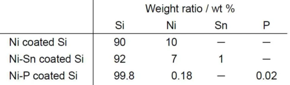
The results of the elemental analysis for the coated Si particles by ELD are summarized in Table 1. For Ni-coated Si particles, we detected 90 wt % Si and 10 wt % Ni. For the coated layers of Ni-Sn and Ni-P, we observed 7 wt % Ni and 1 wt % Sn, and 0.18 wt % Ni and 0.02 wt % P, respectively. The coating amount of Ni-Sn on Si was comparable to that of Ni on Si. On the other hand, the amount of Ni-P coating on Si was 1/50 of the amount of Ni coating on Si, which is a favorable result
because the smaller amount of coated material allows a larger surface area of the Si particles to be exposed and the alloying reaction of Li with Si to occur efficiently.
3.2 Anode properties of GD-film electrodes using Si coated with Ni and Ni-Sn
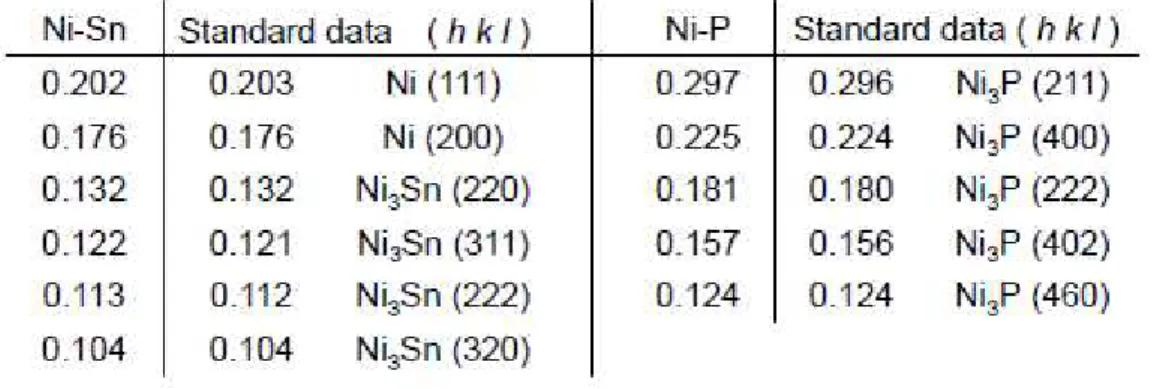
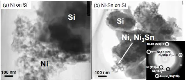
Figures 1(a) and 1(b) depict TEM images of Si particles coated with Ni and Ni-Sn using the ELD method. In each case, we observed larger particles of 1 to 5 µm in size and smaller nanoparticles of 10 nm in size. The smaller nanoparticles were locally deposited on the surface of the larger particles at a thickness of 100~400 nm. In selected area electron diffraction analysis of the larger particles, we obtained spot patterns indicating a crystal phase of Si (JCPDS No. 27-1402). The surface of the Si particles was partially exposed. The d-spacings derived from the diffraction spots of the smaller nanoparticles are summarized in Table 2. Diffraction spots assigned as Ni3Sn [10] appeared to be
associated with the diffuse spots of metallic Ni (JCPDS No. 87-0712). Thus, the main phase of the coated Ni-Sn was revealed to be Ni3Sn.
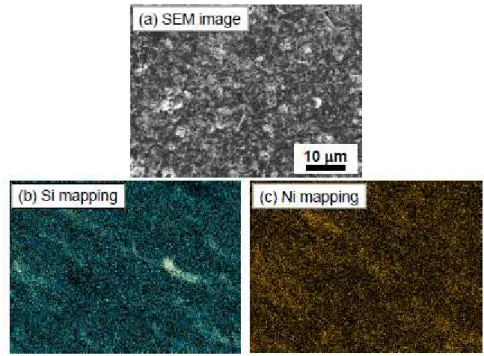
Figure 2 shows an SEM image and the element mapping results for Si and Ni before the charge–discharge tests of the GD-film electrode consisting of Ni-coated Si particle. We can see a rough surface consisting of particles of less than 1 µm in size (Fig. 2(a)). The elemental mapping results indicate that Ni-coated Si particles are uniformly distributed on the substrate (Fig. 2(b) and (c)).
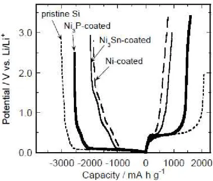
Figure 3 portrays the charge–discharge (Li insertion–extraction) curve for the first cycle for the GD-film electrodes consisting of the coated Si particles. For comparison, the curve was also plotted for the electrode consisting of pristine Si particles. In every case, the potential plateaus were observed at approximately 0.1 and 0.4 V vs. Li/Li+ in the charge and discharge reactions. These potential plateaus are attributed to the alloying and de-alloying reactions of Si with Li.
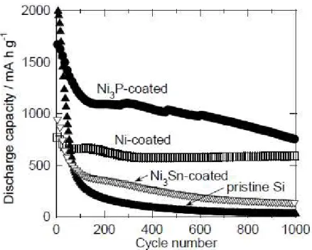
Figure 4 represents the dependence of the discharge (Li-extraction) capacity on the charge–discharge cycling number for the GD-film electrodes consisting of pristine Si and the coated
Si particles. The electrode of pristine Si showed rapid decay of discharge capacity until the 100th cycle, resulting in poor electrode performance. The Ni-coated Si electrode exhibited an initial discharge capacity of 790 mA h g-1, and excellent cycling performance with capacity of 580 mA h g-1
and retention of over 70% at the 1000th cycle. The capacity stability for repeating the charge–discharge cycles in the Ni-coated Si electrode was found to be notably improved compared with the pristine Si electrode. In contrast, the discharge capacity of the electrode consisting of Si coated with Ni3Sn rapidly dropped in the first 100 cycles.
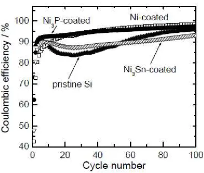
Figure 5 gives the coulombic efficiency of the GD-film electrodes in the first 100 cycles. A significant decrease of the coulombic efficiency was observed for the pristine Si electrode during the first 30 cycles. This indicates that the active materials broke up and/or were electrically isolated by the volumetric changes of Si. In the first cycle, the electrodes of Si coated with Ni and Ni3Sn,
respectively, showed lower coulombic efficiencies of 43% and 48% compared with the pristine Si electrode (73%). The lower efficiencies are attributed to irreversible reactions between the coated materials and the electrolyte in the first cycle. However, the efficiency of the Ni-coated Si electrode steeply rose with increasing cycle number, and maintained high efficiency of over 95% from the 40th cycle. In contrast, the Ni3Sn-coated Si electrode exhibited poor efficiency, similar to the pristine Si
electrode.
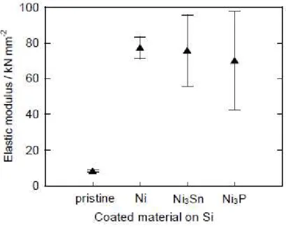
The difference in the electrode performance appears to be caused by the different mechanical properties of the GD-film electrodes. Figure 6 compares the indentation elastic modulus in the various GD-film electrodes. The pristine Si electrode exhibited a very low elastic modulus of approximately 8 kN mm-2, suggesting that the electrode cannot easily release the stress induced by
the volumetric changes in Si during alloying and de-alloying of LixSi, and that the electrode will
extensively collapse in an earlier stage of charge–discharge cycles. The elastic modulus in the Ni-coated Si electrode was about nine times higher than that of the pristine Si electrode. The higher elastic modulus indicates that the Ni layer can effectively release the stress due to the volumetric
changes of Si. Furthermore, Ni is less reactive with Li ions than Ni-Sn, and a thermodynamically-unstable alloy of Li-Ni does not form [11]. Therefore, the surface Ni layer maintained better cycling performance through the suppression of electrode collapse for a long period of 1000 cycles. In contrast, the electrode of Ni3Sn-coated Si exhibited rapid capacity decay
similar to that of the pristine Si electrode, even though the Ni3Sn-coated Si and the Ni-coated Si
electrode have similar elastic moduli before the charge-discharge tests. This result can probably be attributed to the reactivity of Ni3Sn coating with Li ions. The Ni3Sn alloy reacts with Li ions as
shown in the following equations [12–14]:
Ni3Sn + 4.4Li+ + 4.4e− → 3Ni + Li4.4Sn (first cycle)
Sn + 4.4Li+ + 4.4e− ⇄ Li4.4Sn (following cycle)
In the first cycle, Ni3Sn alloy is irreversibly decomposed to form elemental Ni and Sn. Once the
Ni3Sn layers between the Si particles in the electrode are decomposed, the adhesion between Si
particles will be lost. Consequently, little of the Ni3Sn layer remains on the Si particles after the
second cycle. In addition, the formed Sn by the decomposition is also responsible for the charge-discharge of Li ions in association with a drastic volume change. The electrode of Ni3Sn-coated Si could not easily release the stress from the Si particles due to the volume change of
Sn, which leads to accelerated collapse of the electrode in the earlier cycles.
As another effect of the coated-Ni layer on the cycling performance, we must consider that the coated-Ni layer blocks the transfer of Li ions and suppresses the alloying and de-alloying reactions of Li-Si. Although the initial discharge capacity will be decreased as a result, the discharge capacity decay due to the electrode collapse tends to be reduced because the stress induced by the volumetric changes can be reduced. Thus, the reason for the improved cycling performance of the Ni-coated Si electrode remains unresolved. To determine the reason, charge–discharge tests were carried out for the pristine Si electrode by changing the state of charge (SOC).
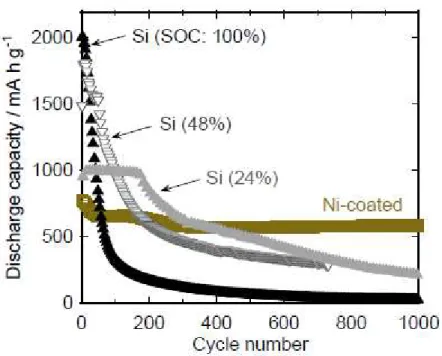
Figure 7 presents the dependence of the cycling performance of the pristine Si electrode on SOC. For comparison, the capacity variation of Ni-coated Si electrode is also plotted in the figure. The plots for SOC of 100% are the same as those for the pristine Si electrode (see Fig. 4). An SOC of 48% means that the charge (Li-insertion) capacity was limited to 48% of the theoretical capacity of Si. The capacity decay for SOC of 48% was suppressed in comparison with that for SOC of 100%. However, the electrode with SOC of 48% continued to exhibit lower capacity compared with the Ni-coated Si electrode after the 200th cycle. Even when the SOC was decreased to 24%, the capacity was lower than that of the Ni-coated Si electrode after the 400th cycle. It is clear that the suppression of the alloying and de-alloying reactions cannot improve the cycling performance for a long period of 1000 cycles. Therefore, we conclude that the reason for the improved cycling performance is the coated-Ni layer, which relaxes the stress induced by the volumetric changes in Si.
In our preliminary experiments using Ni-coated Si electrodes with various amounts of deposited Ni, we have succeeded in enhancing the initial discharge capacity from 790 to 1130 mA h g-1 when
the amount of deposited Ni was decreased from 10 to 6 wt %. However, the discharge capacity rapidly decreased during the first 50 cycles, and the cycling performance of the electrode after 50th cycle was almost the same as that of the electrode consisting of Si coated with 10 wt % Ni. This suggests that the lower amount of deposited Ni is not effective for the further improvement of electrode performance.
3.3 Anode properties of GD-film electrodes using Si coated with Ni-P
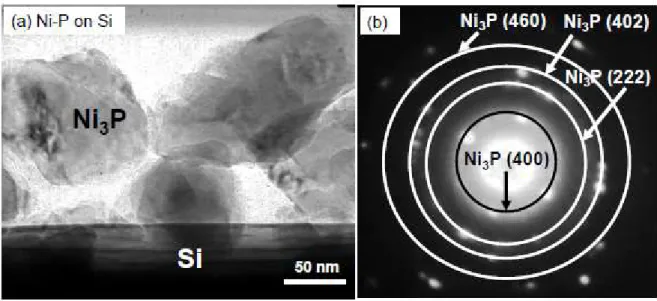
Figures 8(a) and 8(b) display a TEM image and the corresponding selected area electron diffraction of Ni-P coated on Si particles. We confirmed that the exposed surface area on the Si particles was larger than that on the Si particles coated with Ni, and that the layer consisting of aggregated nanoparticles of 60~100 nm in diameter was observed on the edge of Si particles, as shown in Fig. 8(a). The thickness of the layer was about 200 nm. Spotty Debye-Scherrer rings were
obtained from the nanoparticles. The d-spacings derived from the rings clearly corresponded to those of Ni3P (JCPDS No. 74-1384) [15] as described in Table 2.
The elastic modulus of the Si electrode coated with Ni3P was as high as that of Ni-coated Si
electrode (see Fig. 6). We should note that the Ni3P coating markedly improves the elastic modulus,
despite a much smaller amount of Ni3P coating (see Table 1). This suggests that the mechanical
properties of the Ni layer on Si particles were strengthened by the P-doping in accordance with our expectation, which is supported by other results [6–9].
The discharge capacity variation for the electrode of Si coated with Ni3P is shown in Fig. 4. The
discharge capacity at the first cycle was approximately 1590 mA h g-1, which is twice as large as that
of the Ni-coated Si electrode. The less coating amount of Ni3P led the increase in the denuded
surface area of Si particles, and appears to contribute to efficient reactions of Li-Si alloying and de-alloying in the electrode, resulting in doubling the initial capacity. It is noteworthy that the electrode maintained a capacity of 750 mA h g-1 even at the 1000th cycle, which is more than two
times larger than the theoretical capacity of graphite (372 mA h g-1). Although Ni3P undergoes
charge–discharge reactions [16, 17], the reactivity of Ni3P with Li is relatively low in comparison
with Ni3Sn. We consider that the coated Ni3P layer on Si can endure for a greater number of cycles
as a result of its lower reactivity, and can prevent the electrode collapsing due to its high elastic modulus. The coulombic efficiency of the Ni3P-coated Si electrode was 62% in the first cycle as
shown in Fig. 5. The efficiency was higher than that of the Ni-coated Si of 43% and the Ni3Sn-coated
Si of 48%, which is probably attributed to its lower coating amount. We speculate that thin native oxide layers are formed on the coated Ni, Ni3Sn, and Ni3P though we could not confirm the oxides
by the SAED analysis, and that the layers are responsible for large irreversible capacities in the first cycles by formation of thermodynamically stable Li2O. It is suggested that the pristine Si electrodes
exhibited the highest efficiency of 73% in this study because the native oxide layer on the Si particles is negligibly thin. After the first cycle, the coulombic efficiencies of the Ni3P-coated Si
electrode showed much higher compared with the Ni3Sn-coated Si electrode as shown in Fig. 5. The
high efficiency supports our hypothesis regarding the excellent endurance of the Ni3P coating. It was
therefore discovered that the electrode coated with Ni-P is a promising anode, which has both high capacity and excellent cycling performance.
4. Conclusion
In this study, we coated Si particles with Ni, Ni-Sn, and Ni-P by using the ELD technique, and fabricated thick-film electrodes by the GD method using the coated-Si particles. The TEM observations revealed that Ni-Sn and Ni-P which are coated on the Si particles mainly consist of Ni3Sn and Ni3P, respectively. Because of the coating, the elastic modulus of GD-film electrodes
consisting of the coated particles was much higher than that of the pristine Si electrode. The electrode of Ni-coated Si had a discharge capacity of 580 mA h g-1 at the 1000th cycle, and exhibited
notably improved performance in comparison with the Si electrode. Even when the SOC of the pristine Si electrode was decreased to 24%, its capacity was lower than that of the Ni-coated Si electrode after the 400th cycle. The electrode of Si coated with Ni3P with a lower coating amount
exhibited higher initial capacity and excellent cycling performance with a capacity of 750 mA h g-1
at the 1000th cycle, whereas poor performance was observed for the electrode of Si coated with Ni3Sn. The excellent performance in the case of the Ni3P coating can be attributed to the smaller
amount of coating, its high elastic modulus, and the moderate reactivity of Ni3P with Li.
Acknowledgments
This work was supported in part by the Li-EAD program of the New Energy and Industrial Technology Development Organization (NEDO) of Japan. The authors thank Dr. T. Iida for his assistance with electroless deposition. The authors also gratefully acknowledge Prof. K. Ichino and
Mr. Y. Yamamoto for their kind assistance with TEM observations and the charge–discharge tests under various SOC.
References
(1) H. Sakaguchi, T. Toda, Y. Nagao, T. Esaka, Electrochem. Solid-State Lett., 10 (2007) J146.
(2) T. Iida, T. Hirono, N. Shibamura, H. Sakaguchi, Electrochemistry, 76 (2008) 644.
(3) H. Sakaguchi, T. Iida, M. Itoh, N. Shibamura, T. Hirono, IOP Conf. Series: Mater. Sci. Eng., 1 (2009) 012030.
(4) H. Usui, Y. Kashiwa, T. Iida, H. Sakaguchi, J. Power Sources, 195 (2010) 3649.
(5) H. Usui, H. Nishinami, T. Iida, H. Sakaguchi, Electrochemistry, 78 (2010) 329.
(6) F. T. Chi, K. Jiang, B. Li, B. Jiang, Appl. Surf. Sci., 255 (2008) 2740.
(7) P. S. Kumar, P. K. Nair, J. Mater. Proc. Tech., 56 (1996) 511.
(8) M. Palaniappa, S. K. Seshadri, J. Mater. Sci., 42 (2007) 6600.
(9) S.-Y. Chang, Y.-S. Lee, H.-L. Hsiao, T.-K. Chang, Metall. Mater. Trans., 37A (2006) 2939.
(10) S. K. Shadangi, M. Singh, S. C. Panda, S. Bhan, Cryst. Res. Tech., 21 (1986) 867.
(11) A. K. Niessen, F. R. de Boer, R. Boom, P. F. de Châtel, W. C. M. Mattens, Calphad, 7 (1983) 51.
(12) J. Hassoun, S. Panero, B. Scrosati, J. Power Sources, 160 (2006) 1336.
(13) K. Nishikawa, K. Dokko, K. Kinoshita, S.-W. Woo, K. Kanamura, J. Power Sources, 189 (2009) 726.
(14) Q. F. Dong, C. Z. Wu, M. G. Jin, Z. C. Huang, M. S. Zheng, J. K. You, Z. G. Lin, Solid State
Ionics, 167 (2004) 49.
(16) M. Cruz, J. Morales, L. Sánchez, J. Santos-Peña, F. Martín, F. J. Power Sources, 171 (2007) 890.
(17) J. Y. Xiang, J. P. Tu, X. L. Wang, X. H. Huang, Y. F. Yuan, X. H. Xia, Z. Y. Zeng, J. Power
Table 2. Summary of d-spacings (nm) and crystal phase derived from analysis of selected area electron diffraction for Ni-Sn and Ni-P coated on Si particles. The table also lists standard
Fig. 1. TEM images of Si particles coated with (a) Ni and (b) Ni-Sn. Inset shows selected area electron diffraction for smaller nanoparticles of Ni-Sn shown in (b).
Fig. 2. (a) SEM image of GD-film electrode of Ni-coated Si particles and element mapping of (b) Si and (c) Ni.
Fig. 3. Charge–discharge curves during the first cycle for GD-film electrodes consisting of pristine Si and coated Si particles.
Fig. 4. Dependence of discharge capacity on charge–discharge cycling number in GD-film electrodes consisting of pristine Si and coated Si particles.
Fig. 6. Comparison of elastic modulus of GD-film electrodes consisting of pristine Si and coated Si particles.
Fig. 7. Dependence of discharge capacity on charge–discharge cycling number for GD-film electrodes of Ni-coated Si and pristine Si under various states of charge (SOC).
Fig. 8. (a) TEM image and (b) corresponding selected area electron diffraction for Ni-P nanoparticles coated on Si particles.
Figure captions
Table 1. Results of elemental analysis of Si particles coated by ELD.
Table 2. Summary of d-spacings (nm) and crystal phase derived from analysis of selected area electron diffraction for Ni-Sn and Ni-P coated on Si particles. The table also lists standard
d-spacings for Ni (JCPDS No. 87-0712), Ni3Sn [10], and Ni3P [15].
Fig. 1. TEM images of Si particles coated with (a) Ni and (b) Ni-Sn. Inset shows selected area electron diffraction for smaller nanoparticles of Ni-Sn shown in (b).
Fig. 2. (a) SEM image of GD-film electrode of Ni-coated Si particles and element mapping of (b) Si and (c) Ni.
Fig. 3. Charge–discharge curves during the first cycle for GD-film electrodes consisting of pristine Si and coated Si particles.
Fig. 4. Dependence of discharge capacity on charge–discharge cycling number in GD-film electrodes consisting of pristine Si and coated Si particles.
Fig. 5. Dependence of coulombic efficiency of the GD-film electrodes during the first 100 cycles.
Fig. 6. Comparison of elastic modulus of GD-film electrodes consisting of pristine Si and coated Si particles.
Fig. 7. Dependence of discharge capacity on charge–discharge cycling number for GD-film electrodes of Ni-coated Si and pristine Si under various states of charge (SOC).
Fig. 8. (a) TEM image and (b) corresponding selected area electron diffraction for Ni-P nanoparticles coated on Si particles.