Veritas InfoScale Enterprise 7.4.1 for RHEL on AWS
構築手順書
EBS を用いた FSS 構成+ Private IP 切替 編
2019 年 6 月
ベリタステクノロジーズ合同会社
テクノロジーセールス本部
テクニカルホワイトペーパー
2
免責事項
ベリタステクノロジーズ合同会社は、この文書の著作権を留保します。 また、記載された内容の無謬性を保証し
ません。Veritas InfoScale は将来に渡って仕様を変更する可能性を常に含み、これらは予告なく行われること
もあります。なお、当ドキュメントの内容は参考資料として、読者の責任において管理/配布されるようお願いいた
します。
3
目次
免責事項 ... 2
1.
はじめに ... 4
本書の目的 ... 4
2.
システム構成 ... 4
本書の前提となるシステム構成 ... 4
AWS 上に RHEL を構築する場合の注意点 ... 5
3.
インストール ... 7
インストール ... 7
4.
VXVM と VXFS の設定 ... 15
ディスクの確認とイニシャライズ ... 15
ディスクのイニシャライズと
EXPORT
... 15
V
X
VM のディスクグループの作成 ... 16
V
X
VM のボリュームと V
X
FS のファイルシステムの作成 ... 16
既存のサービスグループ:
CVM
への設定追加 ... 17
5.
AWSCLI の設定 ... 19
AWSCLI のインストール ... 19
AWSCLI の構成 ... 19
AWS でのポリシー/ロールの作成と、インスタンスへの割り当て ... 20
6.
クラスターの設定... 26
サービスグループの作成 ... 26
リソースの作成 ... 26
疑似アプリケーションの作成とリソース登録 ... 27
7.
切り替えテスト ... 30
アプリケーションを管理するサービスグループの手動切り替え ... 30
障害によるサービスグループの自動切り替え ... 30
障害ノードの復旧 ... 30
アプリケーション障害 ... 31
4
1. はじめに
本書の目的
本書は、InfoScale Enterprise 7.4.1 を用いて、各ノードのローカルディスクを用いた FSS 構成で、且つ AWS の
Private IP を切り替える 2 ノード稼働待機型クラスター構成の構築の理解を目的に作成されています。
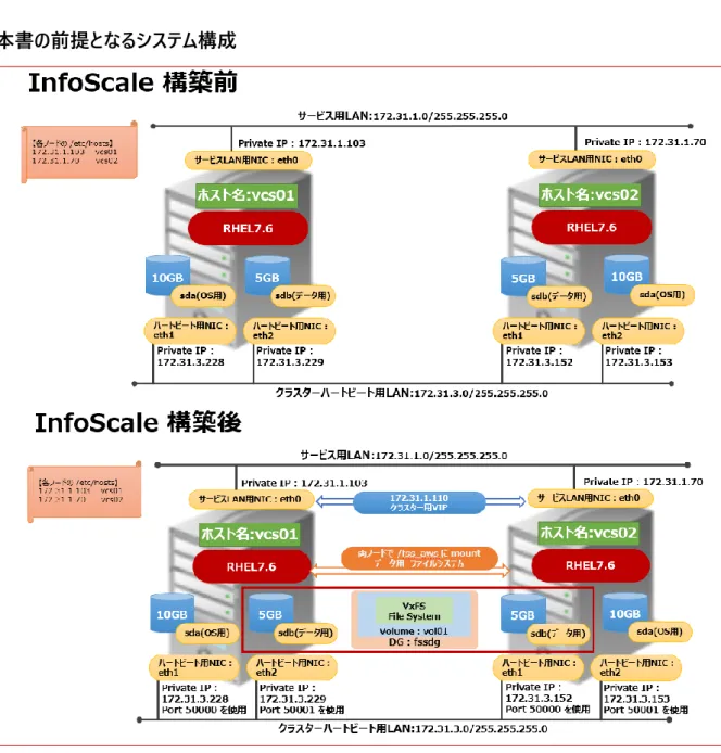
2. システム構成
本書の前提となるシステム構成
5
AWS 上に RHEL を構築する場合の注意点
InfoScale は、AWS 上の RHEL での稼働を保証しています。ただし、InfoScale を構築する場合は、以下の条
件を満たすように RHEL を構築してください。
• ノード間で ping が通ること:InfoScale はインストーラー時や稼働時に、ping による相互監視を行います。
しかし、AWS 上の RHEL はデフォルトで ping が通らない設定になっています。セキュリティグループの「インバ
ウンドの設定」を変更し、ping が通るようにしてください。
• RHEL のインスタンスに ssh を用いて root でパスワードを用いてログインできること:InfoScale のインストー
ル時は、1 台のノードから push install を行いますが、その際に他のノードに ssh を用いて root でパスワードを
用いてログインします。AWS 上で deploy される RHEL は、デフォルトで ssh を用いて root でパスワードを用
いてログインできるようになっていません。/etc/ssh/sshd_config や /etc/passwd を変更してパスワードを
用いて root で ssh ができるようにしてください。
• yum が使用できること: AWS 上で deploy される RHEL には、InfoScale が必要とするパッケージの幾つ
かがインストールされていません。そのため、InfoScale のインストーラーの中で yum を用いて必要なパッケージ
をインストールします。適切なネットワークの設定(踏み台サーバーを経由して yum のサーバーにアクセス等)
もしくは yum のリポジトリの設定を行い、yum が使用できるようにしてください。
• AWSCLI が使用できること: InfoScale は、IP を切り替えるために AWSCLI を使用して EC2 インスタンス
を IAM からコントロールします。InfoScale がインストールされるノードが踏み台サーバーを経由して IAM に接
続できるようにする等して、AWSCLI が使用できるようにしてください。
6
• swap があること:AWS 上で deploy される RHEL には、swap がありません。InfoScale のインストール時
は、swap が必須ですので、ファイルを作成して swap に割り当ててください。
# dd if=/dev/zero of=/home/swapfile bs=1024k count=1024 1024+0 records in
1024+0 records out
1073741824 bytes (1.1 GB) copied, 0.532228 s, 2.0 GB/s # mkswap /home/swapfile
Setting up swapspace version 1, size = 1048572 KiB no label, UUID=f26daf30-7e86-47e3-9bf0-86c47352bac3 # swapon /home/swapfile
swapon: /home/swapfile: insecure permissions 0644, 0600 suggested. # cat /proc/swaps
Filename Type Size Used Priority /home/swapfile file 1048572 0 -2
• データ配置用の EBS が、両方のノードに割り当てられている事: EBS は、共有ディスク構成をサポートせ
ず、EBS は常に1つの EC2 インスタンスにのみ紐付けられます。InfoScale の FSS 構成では、各ノードのロー
カルディスクをクラスターに属する全ノードで仮想的に共有し、ノードをまたいで冗長ボリュームを構成すること
で、AWS 上で共有ディスク構成と同じ環境を提供します。REHL を構築する際は、各ノードに、少なくとも 1
個以上のデータ格納用 EBS を割り当ててください。
7
3. インストール
ここでは、InfoScale Enterprise のインストールを行います。
インストール
メディアイメージ配下の “installer” を実行してください
# ./installer
“I” (Install)を指定して、先に進んでください
Veritas InfoScale Storage and Availability Solutions 7.4.1 Install Program
Task Menu:
P) Perform a Pre-Installation Check I) Install a Product C) Configure a Product Component G) Upgrade a Product O) Perform a Post-Installation Check U) Uninstall a Product L) License a Product S) Start a Product D) View Product Descriptions X) Stop a Product R) View Product Requirements ?) Help
Enter a Task: [P,I,C,G,O,U,L,S,D,X,R,?] I
InfoScale Enterprise をインストールするので、“4”を指定し、Configuration の選択の部分では“4”の
SFCFSHA を指定し、ライセンスに同意して、先に進んでください。
Veritas InfoScale Storage and Availability Solutions 7.4.1 Install Program
1) Veritas InfoScale Foundation 2) Veritas InfoScale Availability 3) Veritas InfoScale Storage 4) Veritas InfoScale Enterprise b) Back to previous menu
Select a product to install: [1-4,b,q,?] 4
Would you like to configure InfoScale Enterprise after installation? [y,n,q] (n) y
1) Cluster Server (VCS) 2) Storage Foundation (SF)
3) Storage Foundation and High Availability (SFHA) 4) Storage Foundation Cluster File System HA (SFCFSHA) 5) Storage Foundation for Oracle RAC (SF Oracle RAC)
Select a component to configure: [1-5,q] 4
This product may contain open source and other third party materials that are subject to a separate license. See the applicable
Third-Party Notice at https://www.veritas.com/about/legal/license-agreements
Do you agree with the terms of the End User License Agreement as specified in the EULA/en/EULA.pdf file present on media?
8
インストールすべきホスト名を指定して、先に進んでください。複数のノードに同時にインストール可能で
す。
Enter the system names separated by spaces: [q,?] vcs01 vcs02
途中略
キーレスライセンス:”2” を選択し、”4”の「Veritas InfoScale Enterprise」を指定して先に進んでくださ
い。
Veritas InfoScale Enterprise 7.4.1 Install Program vcs01 vcs02
To comply with the terms of our End User License Agreement, you have 60 days to either:
* Enter a valid license key matching the functionality in use on the systems
* Enable keyless licensing and manage the systems with a Management Server. For more details visit http://www.veritas.com/community/blogs/introducing-keyless-feature-enablement-storage-foundation-ha-51. The product is fully functional during these 60 days.
1) Enter a valid license key(Key file path needed)
2) Enable keyless licensing and complete system licensing later
How would you like to license the systems? [1-2,q] (2) 2
1) Veritas InfoScale Foundation 2) Veritas InfoScale Availability 3) Veritas InfoScale Storage 4) Veritas InfoScale Enterprise b) Back to previous menu
Which product would you like to register? [1-4,b,q] (4) 4 Registering keyless key ENTERPRISE on Veritas InfoScale Enterprise Successfully registered ENTERPRISE keyless key on vcs01
Successfully registered ENTERPRISE keyless key on vcs02
InfoScale7.4.1 から、Veritas Telemetry Collector が実装されました。これは、顧客が望む場合に
限り、InfoScale の情報をネットワーク経由でベリタスに送付し、ベリタス主体でライセンス管理等を行
えるようにするオプション機能です。もちろん使用しない事も可能です。インストーラーでは、この機能を使
用する前提でエッジサーバーの IP とポートの情報を要求します。本件では、Veritas Telemetry
Collector は使用しませんので、エッジサーバーの IP アドレスとポートは実在しない物を指定します。実
在しない物を指定しても、インストールは正しく行われ、InfoScale も問題なく機能しますので、ご安心く
ださい。
The Veritas Cloud Receiver (VCR) is a preconfigured, cloud-based edge server deployed by Veritas. Enter telemetry.veritas.com to use the Veritas Cloud Receiver as an edge server for your environment. Enter the edge server's hostname/ip: [q,?] 172.31.3.115
CPI WARNING V-9-40-1382 Could not ping the Edge server 172.31.3.115 from following hosts: vcs01 vcs02 Please make sure 172.31.3.115 is accessible from vcs01 vcs02 for telemetry collector to work. Installer will proceed.
Press [Enter] to continue:
9
本書の前提では、I/O Fencing は構成しないので、”n” を指定して先に進んでください。
I/O FencingIt needs to be determined at this time if you plan to configure I/O Fencing in enabled or disabled mode, as well as help in determining the number of network interconnects (NICS) required on your systems. If you configure I/O Fencing in enabled mode, only a single NIC is required, though at least two are recommended.
A split brain can occur if servers within the cluster become unable to communicate for any number of reasons. If I/O Fencing is not enabled, you run the risk of data corruption should a split brain occur. Therefore, to avoid data corruption due to split brain in CFS environments, I/O Fencing has to be enabled.
If you do not enable I/O Fencing, you do so at your own risk
See the Administrator's Guide for more information on I/O Fencing
Do you want to configure I/O Fencing in enabled mode? [y,n,q,?] (y) n
Enter を押して次に進んでください。
Veritas InfoScale Enterprise 7.4.1 Install Program vcs01 vcs02
To configure VCS, answer the set of questions on the next screen.
When [b] is presented after a question, 'b' may be entered to go back to the first question of the configuration set.
When [?] is presented after a question, '?' may be entered for help or additional information about the question.
Following each set of questions, the information you have entered will be presented for confirmation. To repeat the set of questions and correct any previous errors, enter 'n' at the confirmation prompt.
No configuration changes are made to the systems until all configuration questions are completed and confirmed.
Press [Enter] to continue:
クラスター名をしていします。これは任意なので、今回は fss を指定しています。
Veritas InfoScale Enterprise 7.4.1 Install Program vcs01 vcs02To configure VCS for InfoScale Enterprise the following information is required:
A unique cluster name
Two or more NICs per system used for heartbeat links A unique cluster ID number between 0-65535
One or more heartbeat links are configured as private links You can configure one heartbeat link as a low-priority link
All systems are being configured to create one cluster.
10
ハートビートの設定方法は” LLT over UDP”を指定します。AWS 上で FSS を構成する場合、ハートビー
トは LLT over UDP のみがサポートされます。また、この場合はオンプレと同じように各ノードで 2 つのハー
トビート用 NIC が必要です。ハートビート用 NIC にはあらかじめ IP を振っておき、以下のように設定しま
す。
Veritas InfoScale Enterprise 7.4.1 Install Program vcs01 vcs02
1) Configure the heartbeat links using LLT over Ethernet 2) Configure the heartbeat links using LLT over UDP 3) Configure the heartbeat links using LLT over TCP 4) Configure the heartbeat links using LLT over RDMA 5) Automatically detect configuration for LLT over Ethernet b) Back to previous menu
How would you like to configure heartbeat links? [1-5,b,q,?] (5) 2
Discovering NICs on vcs01 ... Discovered eth0 eth1 eth2 Enter the NIC for the first private heartbeat link on vcs01: [b,q,?] (eth1)
Some configured IP addresses have been found on the NIC eth1 in vcs01, Do you want to choose one for the first private
heartbeat link? [y,n,q,?] (y) y Please select one IP address: 1) 172.31.3.228/24
2) fe80::4a6:80ff:fe97:b36/64 b) Back to previous menu
Please select one IP address: [1-2,b,q,?] (1) 1
Enter the UDP port for the first private heartbeat link on vcs01: [b,q,?] (50000) 50000
Enter the NIC for the second private heartbeat link on vcs01: [b,q,?] eth2
Some configured IP addresses have been found on the NIC eth0 in vcs01, Do you want to choose one for the second private
heartbeat link? [y,n,q,?] (y) y Please select one IP address: 1) 172.31.3.229/24
2) fe80::4eb:35ff:fed6:96ce/64 b) Back to previous menu
Please select one IP address: [1-2,b,q,?] (1) 1
Enter the UDP port for the second private heartbeat link on vcs01: [b,q,?] (50001) 50001
Do you want to configure an additional low-priority heartbeat link? [y,n,q,b,?] (n) n
Are you using the same NICs for private heartbeat links on all systems? [y,n,q,b,?] (y) y
Some configured IP addresses have been found on the NIC eth1 in vcs02, Do you want to choose one for the first private
heartbeat link? [y,n,q,?] (y) y Please select one IP address: 1) 172.31.3.152/24
2) fe80::430:c4ff:fe68:4120/64 b) Back to previous menu
Please select one IP address: [1-2,b,q,?] (1) 1 The UDP Port for this link: 50000
Some configured IP addresses have been found on the NIC eth2 in vcs02, Do you want to choose one for the second private
heartbeat link? [y,n,q,?] (y) y
(次ページに続く)
11
1) 172.31.3.153/24
2) fe80::4ae:1dff:fe2b:e010/64 b) Back to previous menu
Please select one IP address: [1-2,b,q,?] (1) 1 The UDP Port for this link: 50001
Checking media speed for eth1 on vcs01 ... Unknown Checking media speed for eth2 on vcs01 ... Unknown Checking media speed for eth1 on vcs02 ... Unknown Checking media speed for eth2 on vcs02 ... Unknown
CPI WARNING V-9-40-3128 installer cannot detect media speed for the selected private NICs properly. Consult your Operating
System manual for information on how to set the Media Speed.
Do you want to continue with current heartbeat configuration? [y,n,q] (y) y
クラスターID は、0~65535 からランダムに指定されます。同一ネットワークセグメント上でクラスターID
が重複しない必要があります。チェックが通ったら次に進みます。
Enter a unique cluster ID number between 0-65535: [b,q,?] (9140)
The cluster cannot be configured if the cluster ID 9140 is in use by another cluster. Installer can perform a check to
determine if the cluster ID is duplicate. The check will take less than a minute to complete.
Would you like to check if the cluster ID is in use by another cluster? [y,n,q] (y) y
Checking cluster ID ... Done
Duplicated cluster ID detection passed. The cluster ID 9140 can be used for the cluster.
12
内容をチェックして、問題なければ先に進んでください。
Veritas InfoScale Enterprise 7.4.1 Install Program vcs01 vcs02
Cluster information verification:
Cluster Name: fss Cluster ID Number: 9140
Private Heartbeat NICs for vcs01: link1=eth1 over UDP
ip 172.31.3.228 netmask 255.255.255.0 port 50000 link2=eth2 over UDP
ip 172.31.1.229 netmask 255.255.255.0 port 50001
Private Heartbeat NICs for vcs02: link1=eth1 over UDP
ip 172.31.3.152 netmask 255.255.255.0 port 50000 link2=eth2 over UDP
ip 172.31.1.153 netmask 255.255.255.0 port 50001 LLT tagging:
When configuring LLT over UDP or TCP, tags are used in LLT configuration file with set-addr option. Due to this, LLT configuration file may use local NIC identifiers referring to remote IP addresses.
Is this information correct? [y,n,q,?] (y) y
本書では、インストール時にクラスターの仮想 IP を設定する必要はないので “n” を答えて先に進んでく
ださい。
Veritas InfoScale Enterprise 7.4.1 Install Program vcs01 vcs02
The following data is required to configure the Virtual IP of the Cluster:
A public NIC used by each system in the cluster A Virtual IP address and netmask
Do you want to configure the Virtual IP? [y,n,q,?] (n) n
本書では、VCS をセキュアモードで設定しないので、”n” に続いて “y” を指定し、先に進んでください。
Veritas InfoScale Enterprise 7.4.1 Install Programvcs01 vcs02
We recommend that you run Cluster Server in secure mode.
Running VCS in Secure Mode guarantees that all inter-system communication is encrypted, and users are verified with security credentials.
When running VCS in Secure Mode, NIS and system usernames and passwords are used to verify identity. VCS usernames and passwords are no longer utilized when a cluster is running in Secure Mode.
Would you like to configure the VCS cluster in secure mode? [y,n,q,?] (y) n
CPI WARNING V-9-40-3394 We recommend that you install the cluster in secure mode. This ensures that communication between cluster components is encrypted and cluster information is visible to specified users only.
13
VCS のオペレーションを行うためのユーザーとパスワードを設定します。この ID は、複数の VCS 同士で連
携したり、OS に root 以外でログインしたユーザーで VCS のオペレーションを行う際に必要です。本書で
は、デフォルトのユーザー:admin のみを設定しています。
Veritas InfoScale Enterprise 7.4.1 Install Program vcs01 vcs02
The following information is required to add VCS users:
A user name
A password for the user
User privileges (Administrator, Operator, or Guest)
Do you wish to accept the default cluster credentials of 'admin/password'? [y,n,q] (y) y
Do you want to add another user to the cluster? [y,n,q] (n) n
内容を確認し、”y” を指定して先に進んでください。
Veritas InfoScale Enterprise 7.4.1 Install Program vcs01 vcs02
VCS User verification:
User: admin Privilege: Administrators
Passwords are not displayed
Is this information correct? [y,n,q] (y) y
本書では、SMTP 通知は行わないので “n” を指定して先に進んでください。
Veritas InfoScale Enterprise 7.4.1 Install Program vcs01 vcs02The following information is required to configure SMTP notification:
The domain-based hostname of the SMTP server The email address of each SMTP recipient
A minimum severity level of messages to send to each recipient
Do you want to configure SMTP notification? [y,n,q,?] (n) n
本書では、SNMP 通知は行わないので “n” を指定して先に進んでください。
Veritas InfoScale Enterprise 7.4.1 Install Program vcs01 vcs02The following information is required to configure SNMP notification:
System names of SNMP consoles to receive VCS trap messages SNMP trap daemon port numbers for each console
A minimum severity level of messages to send to each console
14
本書では、グローバルクラスターの設定は行わないので “n” を指定して先に進んでください。
Veritas InfoScale Enterprise 7.4.1 Install Programvcs01 vcs02
The following data is required to configure the Global Cluster Option:
A public NIC used by each system in the cluster A Virtual IP address and netmask
Do you want to configure the Global Cluster Option? [y,n,q,?] (n) n
インストールを続行するには、関連プロセスやドライバーの再起動が必要です。”y” を指定して先に進ん
でください。
All InfoScale Enterprise processes that are currently running must be stopped
Do you want to stop InfoScale Enterprise processes now? [y,n,q,?] (y) y
途中略
Storage Foundation Cluster File System HA Startup completed successfully
The updates to VRTSaslapm package are released via the SORT web page: https://sort.veritas.com/asl. To make sure you have the
latest version of VRTSaslapm (for up to date ASLs and APMs), download and install the latest package from the SORT web page.
After configuring the cluster, you can configure application monitoring using Veritas InfoScale Operation Manager. To launch the High Availability Configuration Wizard:
1. Log on to the Veritas InfoScale Operation Manager Management Server domain.
2. In the Veritas InfoScale Operation Manager home page, click the Availability icon from the list of perspectives. 3. Locate the cluster and then right-click on the cluster or on one of the systems under the cluster.
4. Click Configure Application.
Installation procedures and diagnostic information are saved in the log files under directory
/var/tmp/installer-201906020434JAi. This information helps us identify and resolve failed operations performed by the
installer. Would you like to send the information to us to help improve installation in the future? [y,n,q,?] (y) n
Checking online updates for Veritas InfoScale Enterprise 7.4.1
No updates available for Veritas InfoScale Enterprise 7.4.1
Visit https://sort.veritas.com for more information.
installer log files, summary file, and response file are saved at:
/opt/VRTS/install/logs/installer-201906020434JAi
Would you like to view the summary file? [y,n,q] (n) n
#
これで、InfoScale のインストールは終了です。インストール時に問題が発生した場合は、インストーラーの
最後で表示された/opt/VRTS/install/logs 配下のログを収集してください。
15
4. VxVM と VxFS の設定
ディスクの確認とイニシャライズ
まず、VxVM から認識されているディスクの確認とイニシャライズを行います。
オペレーションの準備
オペレーションを始める前に、両方のノードで PATH と MANPATH の設定を行ってください。
# PATH=$PATH:/opt/VRTS/bin export PATH # MANPATH=$MANPATH/opt/VRTS/man export MANPATH
ディスクのイニシャライズと export
1 号機で認識できているディスクを確認してください。OS のディスク以外に、1 本のディスクが見えていま
す。データ用にこのディスクを使用します。
# vxdisk list
DEVICE TYPE DISK GROUP STATUS
xvda auto:none - - online invalid
01_xen-vd0_1 auto:none - - online invalid
前述のディスクをイニシャライズし、その後で export してください。
# vxdisksetup -i 01_xen-vd0_1
# vxdisk export 01_xen-vd0_1
2 号機でも、同じようにディスクのイニシャライズと export を行ってください。
# vxdisk list
DEVICE TYPE DISK GROUP STATUS
xvda auto:none - - online invalid
02_xen-vd0_1 auto:none - - online invalid
# vxdisksetup -i 02_xen-vd0_1
# vxdisk export 02_xen-vd0_1
1 号機及び 2 号機で、vxdctl enable でディスクの再走査を行った後に、再度 vxdisk list を実行す
ると、他方のノードのディスクが見えるようになります。下記は、1号機の出力例です。
# vxdctl enable
# vxdisk list
DEVICE TYPE DISK GROUP STATUS
xvda auto:none - - online invalid
01_xen-vd0_1 auto:cdsdisk - - online remote
02_xen-vd0_1 auto:cdsdisk - - online exported
16
VxVM のディスクグループの作成
次に、ディスグループを作成します。ディスクグループは、Linux の LVM で言う所の Volume Group に相当し、
VxVM でボリューム(仮想デバイス)を作成して使用する場合は、ボリュームは必ずいずれかのディスクグループに
所属している必要があります。本書のクラスターは、FSS 構成であるため、双方のノードの内蔵ディスクをお互いに
シェアした fss ディスクグループを作成します。
ディスクグループの作成
1 号機で vxdg コマンドを用いて、以下の例に従って fssdg という名前のディスクグループを作成しま
す。ディスクとして 01_xen-vd0_1 02_xen-vd0_1 の 2 本を使用しています。
# vxdg -s -o fss init fssdg 01_xen-vd0_1 02_xen-vd0_1
ディスクグループの作成に成功すると、vxdisk list コマンドの出力は以下のようになり、従来空欄だった
“GROUP” の列にディスクグループ名である “awsdg” が表示されます。
# vxdisk list
DEVICE TYPE DISK GROUP STATUS
xvda auto:none - - online invalid
01_xen-vd0_1 auto:cdsdisk 01_xen-vd0_1 fssdg online exported shared
02_xen-vd0_1 auto:cdsdisk 02_xen-vd0_1 fssdg online shared remote
VxVM のボリュームと VxFS のファイルシステムの作成
次に、ボリュームを作成します。ボリュームは、Linux の LVM で言う所の Volume に相当します。ボリュームを作製
したら、そこにファイルシステムを構築します。この作業は 1 号機のみで行います。
まず、VxVM のボリュームを作製します。下記例では、”fssdg” というディスクグループ内の
“01_xen-vd0_0” と ”02_xen-vd0_1” の2本のディスクを用いて、“vol01” という名前の容量 1Gbyte のミラー
ボリュームを作成しています。
17
作製したボリュームは、vxprint コマンドで確認できます。
# vxprint
Disk group: fssdg
TY NAME ASSOC KSTATE LENGTH PLOFFS STATE TUTIL0 PUTIL0
dg fssdg fssdg - - - - - -
dm 01_xen-vd0_1 01_xen-vd0_1 - 10411776 - - - -
dm 02_xen-vd0_1 02_xen-vd0_1 - 10411776 - REMOTE - -
v vol01 fsgen ENABLED 2097152 - ACTIVE - -
pl vol01-01 vol01 ENABLED 2097152 - ACTIVE - -
sd 01_xen-vd0_1-01 vol01-01 ENABLED 2097152 0 - - -
pl vol01-02 vol01 ENABLED 2097152 - ACTIVE - -
sd 02_xen-vd0_1-01 vol01-02 ENABLED 2097152 0 - - -
dc vol01_dco vol01 - - - - - -
v vol01_dcl gen ENABLED 67840 - ACTIVE - -
pl vol01_dcl-01 vol01_dcl ENABLED 67840 - ACTIVE - -
sd 01_xen-vd0_1-02 vol01_dcl-01 ENABLED 67840 0 - - -
pl vol01_dcl-02 vol01_dcl ENABLED 67840 - ACTIVE - -
sd 02_xenvd0_102 vol01_dcl02 ENABLED 67840 0
-作製されたボリューム上にファイルシステムを作製します。指定するデバイスパス名は /dev/vx/rdsk まで
が固定で、その後にディスクグループ名(下記例では fssdg)、最後にボリューム名(下記例では
vol01)、というフォーマットです。
# mkfs -t vxfs /dev/vx/rdsk/fssdg/vol01
version 15 layout
2097152 sectors, 1048576 blocks of size 1024, log size 16384 blocks
rcq size 1024 blocks
largefiles supported
maxlink supported
WORM not supported
既存のサービスグループ:cvm への設定追加
本構成では、インストール時に(7 ページに記述)SFCFSHA を指定しているので、自動的に cvm というサービス
グループが作成されています。作成したファイルシステムを mount して使用するためには、このサービスグループにリ
ソースを追加する必要があります。この作業は、特に断りがない限り 1 号機のみで行います。
まず、クラスターの構成を編集可能にするモード設定を行ってください。
[root@node01 ~]# haconf -makerw
18
下記では、使用するディスクグループ:fssdg とボリューム vol01 を管理・監視するリソース:voldg を追加
しています。最後に、このリソースの online の条件が、既に構成済みのリソースである cvm_clus の
online である事を設定しています。
# hares -add voldg CVMVolDg cvm
VCS NOTICE V-16-1-10242 Resource added. Enabled attribute must be set before agent
monitors
# hares -modify voldg CVMDiskGroup fssdg
# hares -modify voldg CVMActivation sw
# hares -modify voldg CVMVolume vol01
# hares -modify voldg Critical 0
# hares -modify voldg Enabled 1
# hares -link voldg cvm_clus
次に、ファイルシステムを mount するリソース:mount を作製します。このリソースの online の条件
が、既に構成済みのリソースである voldg の online である事を設定しています。尚、このリソースを作
製する際に、1 号機と 2 号機で mount point : /fss_aws を作製しておいてください。
# hares -add mount CFSMount cvm
VCS NOTICE V-16-1-10242 Resource added. Enabled attribute must be set before agent
monitors
[root@vcs01 /]# hares -modify mount MountPoint /fss_aws
[root@vcs01 /]# hares -modify mount BlockDevice /dev/vx/dsk/fssdg/vol01
[root@vcs01 /]# hares -modify mount Enabled 1
[root@vcs01 /]# hares -link mount voldg
[root@vcs01 /]#
[root@vcs01 /]# mkdir /fss_aws
サービスグループ: cvm を 1 号機と 2 号機で online にします。
# hagrp -online cvm -any
VCS NOTICE V-16-1-50735 Attempting to online group on system vcs01
VCS NOTICE V-16-1-50735 Attempting to online group on system vcs02
Online になったかどうかは、hastatus と df で確認してください。
# hastatus -sum
-- SYSTEM STATE
-- System State Frozen
A vcs01 RUNNING 0
A vcs02 RUNNING 0
-- GROUP STATE
-- Group System Probed AutoDisabled State
B cvm vcs01 Y N ONLINE
B cvm vcs02 Y N ONLINE
# df -h
Filesystem Size Used Avail Use% Mounted on
/dev/xvda2 10G 6.9G 3.2G 69% /
devtmpfs 3.8G 0 3.8G 0% /dev
tmpfs 3.9G 0 3.9G 0% /dev/shm
tmpfs 3.9G 17M 3.9G 1% /run
tmpfs 3.9G 0 3.9G 0% /sys/fs/cgroup
tmpfs 782M 0 782M 0% /run/user/0
/dev/vx/dsk/fssdg/vol01 1.0G 36M 927M 4% /fss_aws
19
5. AWSCLI の設定
ここでは、AWSCLI の設定を行います。
AWSCLI のインストール
まず、両方のノードで AWSCLI をインストールしてください。
まず、AWSCLI をサイトからダウンロードし、解凍します。
# curl "https://s3.amazonaws.com/aws-cli/awscli-bundle.zip" -o "awscli-bundle.zip"
# unzip awscli-bundle.zip
# ls
awscli-bundle awscli-bundle.zip
次に、AWSCLI のインストールを行います。
# cd awscli-bundle
# ls
install packages
# ./install -i /usr/local/aws -b /usr/local/bin/aws
Running cmd: /usr/bin/python virtualenv.py --no-download --python /usr/bin/python
/usr/local/aws
Running cmd: /usr/local/aws/bin/pip install --no-cache-dir --no-index --find-links
file:///home/aws/awscli-bundle/packages/setup setuptools_scm-1.15.7.tar.gz
Running cmd: /usr/local/aws/bin/pip install --no-cache-dir --no-index --find-links
file:///home/aws/awscli-bundle/packages awscli-1.16.167.tar.gz
You can now run: /usr/local/bin/aws --version
AWSCLI の構成
RHEL のインスタンスが立ち上がる region を確認したら、AWSCLI の構成を行います。Access Key と
Secret Key を入力する必要はありません。
# /usr/local/bin/aws configure AWS Access Key ID [None]: AWS Secret Access Key [None]:
Default region name [None]: ap-northeast-1 Default output format [None]:json
※
「Default output format」は、必ず「json」にしてください。「json」以外では、InfoScale は AWSCLI
20
AWS でのポリシー/ロールの作成と、インスタンスへの割り当て
InfoScale がインストールされたノードから AWSCLI を使用する際、セキュリティリスク回避の観点から、クラスター
の動作に必要な機能のみが可能になるべきです。その為に、ポリシーとロールを作成し、それを InfoScale がイン
ストールされたノード(インスタンス)に割り当てます。
IAM のメニューからポリシーを選択します
「ポリシーの作成」を選択します
21
「VCS」という名称でポリシーを作成し、「編集」メニューで内容を決定します。以下例の Action のみ可
能になるように設定してください。これらの Action は、IP の切り替えに必要なものだけを列挙していま
す。
22
次にロールを作成します。IAM のメニューからロールの作成を選択します
23
ロールにアタッチするポリシーを選択します。先ほど作成したポリシー:VCS をアタッチします。
24
「VCSRole」というロール名を指定し、ロールが作成できました。
作成したロールを、InfoScale がインストールされるインスタンスに紐づけます。EC2 のメニューの「インスタ
ンス」でインスタンス一覧を表示し、作成したロールに紐付けたいインスタンスを右クリックして「IAM ロー
ルの割り当て/置換」を選択してください。
25
下記の例の通り、「VCSRole」というロールをインスタンスに紐付けます
インスタンスの詳細を表示して、正しく紐付けられたことを確認してください
最後に、InfoScale がインストールされるノード上で AWSCLI が正しく機能することを確認します。20 ペ
ージで許可した Action の全てが使用できることを確認してください。下記例では、20 ページで指定した
「DescribeAddresses」が可能か確認しています。Action 名のフォーマットが異なりますので(コマンド
ラインでは、describe-addresses)、注意してください。
# aws ec2 describe-addresses
{
"Addresses": [
{
"Domain": "vpc",
"PublicIpv4Pool": "amazon",
"InstanceId": "i-0b983c70a3383be39",
(以下略)
26
6. クラスターの設定
いよいよ、AWS 上の RHEL 上で、アプリケーション及びその稼働に必要な個々のコンポーネントが、InfoScale に
よって適切に監視/リカバリーされるための設定を行います。この作業は、どちらか一方ノーノードから行います。
サービスグループの作成
アプリケーション及びその稼働に必要な個々のコンポーネントの集合体を「サービスグループ」と呼びます。切り替え
は、このサービスグループ単位で行います。
まず、クラスターの構成を編集可能にするためのモード設定を行ってください。
# haconf -makerw
サービスグループ:testsg を作製します。このサービスグループは、クラスターが立ち上がる際に、自動的
にオンラインになる設定にしています。自動的にオンラインにしたい場合は、「hagrp -modify testsg
AutoStartList vcs01 vcs02」を省略してください。また、サービスグループ:testsg が online になる条件
として、同じノードでサービスグループ:cvm である事を設定しています。
# hagrp -add testsg
VCS NOTICE V-16-1-10136 Group added; populating SystemList and setting the Parallel
attribute recommended before adding resources
# hagrp -modify testsg Parallel 0
# hagrp -modify testsg SystemList vcs01 0 vcs02 1
# hagrp -modify testsg AutoStartList vcs01 vcs02
# hagrp -link testsg cvm online local firm
リソースの作成
サービスグループに属するアプリケーション及びその稼働に必要な個々のコンポーネントそれぞれを「リソース」と呼び
ます。監視は、このリソース単位で行われます。
作成したサービスグループ内にリソース:nic を作製します。このリソースは、サービス用 Private IP アドレ
スを立ち上げる NIC を監視します。監視対象 NIC は eth0 です。
# hares -add nic NIC testsg
VCS NOTICE V-16-1-10242 Resource added. Enabled attribute must be set before agent
monitors
# hares -modify nic Device eth0
# hares -modify nic Enabled 1
27
次にリソース:ip を作製します。このリソースは、サービスで使用する Private IP アドレスを立ち上げ、そ
れを監視します。IP アドレスは 172.31.1.110 です。このリソースの online の条件が、既に構成済みの
リソースである nic の online である事を設定します。
# hares -add ip IP testsg
# hares -modify ip Device eth0
# hares -modify ip Address 172.31.1.110
# hares -modify ip NetMask 255.255.255.0
# hares -modify ip Enabled 1
# hares -link ip nic
次にリソース:awsip を作製します。このリソースは、nic リソースでインスタンス内に立ち上げた Private
IP に、VPC 内の他のインスタンスからアクセスできるようにします。尚、AWSBinDir のパラメーターには、
AWSCLI を構成する際に設定した「aws コマンドが格納された絶対パス」を正確に指定してください。
最後に、このリソースの online の条件が、既に構成済みのリソースである ip の online である事を設定
します。
# hares -add awsip AWSIP testsg
# hares -modify awsip PrivateIP 172.31.1.110
# hares -modify awsip Device eth0
# hares -modify awsip AWSBinDir /usr/local/aws/bin
# hares -modify awsip Enabled 1
# hares -link awsip ip
疑似アプリケーションの作成とリソース登録
クラスターの動作確認の為に疑似的なアプリケーションを作成し、その切り替えと監視を行うリソースを作成しま
す。
下記が擬似アプリケーションです。自身のプロセス ID を/tmp/datetime.pid に保存した後、5 秒に一
回の間隔で、データ用 EBS 上に構築されたファイルシステム配下に日付とホスト名を書き込みます。
# cat /usr/local/bin/app.sh
#!/bin/sh
echo $$ > /tmp/datetime.pid
while :
do
date >> /fss_aws/date.dat
hostname >> /fss_aws/date.dat
sleep 5
done
下記が、擬似アプリケーションを起動するシェルです。
# cat /usr/local/bin/start.sh
#!/bin/sh
/usr/local/bin/app.sh &
exit 0
28
下記が、擬似アプリケーションを停止するシェルです。
# cat /usr/local/bin/stop.sh
#!/bin/sh
kill `cat /tmp/datetime.pid`
rm -f /tmp/datetime.pid
exit 0
下記が擬似アプリケーションを監視するシェルです。擬似アプリケーションのプロセス ID ファイルが存在す
るかどうかを確認し、存在すれば exit110(online)、存在しなければ exit100(offline)で終了し
ます。
# cat /usr/local/bin/monitor.sh
#!/bin/bash
if [ -e /tmp/datetime.pid ]; then
exit 110
else
exit 100
fi
擬似アプリケーションと、それを起動・停止・監視する為のスクリプトを作製し、全てのノードに同じ絶対
パスで保存したら、これらを制御するリソース:app を作製します。このリソースの online の条件が、既に
構成済みのリソースである awsip の online である事を設定します。
# hares -add app Application testsg
VCS NOTICE V-16-1-10242 Resource added. Enabled attribute must be set before agent
monitors
# hares -modify app StartProgram /usr/local/bin/start.sh
# hares -modify app StopProgram /usr/local/bin/stop.sh
# hares -modify app MonitorProgram /usr/local/bin/monitor.sh
# hares -modify app Enabled 1
# hares -link app awsip
サービスグループ: testsg の設定が完了したら、このサービスグループを 1 号機で online にします。
# hagrp -online testsg -sys vcs01
29
サービスグループが 1 号機で online になっており、1 号機で Private IP : 172.31.1.110 が立ち上がって
おり、疑似アプリケーションが動作していることを確認します。
# hastatus -sum
-- SYSTEM STATE
-- System State Frozen
A vcs01 RUNNING 0
A vcs02 RUNNING 0
-- GROUP STATE
-- Group System Probed AutoDisabled State
B testsg vcs01 Y N ONLINE
B testsg vcs02 Y N OFFLINE
#
# ifconfig -a | grep 172.31.1.110
inet 172.31.1.110 netmask 255.255.255.0 broadcast 172.31.1.255
# tail /fss_aws/date.dat
Fri May 31 05:26:20 UTC 2019
vcs01
Fri May 31 05:26:25 UTC 2019
vcs01
Fri May 31 05:26:30 UTC 2019
vcs01
Fri May 31 05:26:35 UTC 2019
vcs01
#
最後に、必ずクラスターの構成をディスクに反映させ、編集不可にするモード設定を行ってください。これ
を行わないと、サーバー再起動やクラスターの停止時に、そこまでの設定変更が無効になってしまいま
す。
30
7. 切り替えテスト
最後に、AWS 上の RHEL 上で、アプリケーション及びその稼働に必要な個々のコンポーネントが、InfoScale によ
って適切に監視/リカバリーされるかを確認するための簡単なテストを行います。
アプリケーションを管理するサービスグループの手動切り替え
以下のコマンドで、サービスグループが 2 号機に切り替わります。
# hagrp –switch testasg –to vcs02
2 号機への切り替えが正常に完了すると、hastatus の結果は以下のようになります。
# hastatus -sum
-- SYSTEM STATE
-- System State Frozen
A vcs01 RUNNING 0
A vcs02 RUNNING 0
-- GROUP STATE
-- Group System Probed AutoDisabled State
B cvm vcs01 Y N ONLINE
B cvm vcs02 Y N ONLINE
B testsg vcs01 Y N OFFLINE
B testsg vcs02 Y N ONLINE
障害によるサービスグループの自動切り替え
アプリケーションが稼働している方の RHEL インスタンスを、AWS の EC2 のコンソールから停止してくださ
い。 その後で、生き残ったノードに正しくサービスグループが切り替わっていることを ifconfig や hastatus
で確認してください。
障害ノードの復旧
上記のテストで停止したノードを AWS の EC2 のコンソールから再立ち上げし、立ち上がったノードにサー
ビスグループを手動で切り替えてください。この前と後で、各ノードの ifconfig や df や hastatus の表示
がどう変わったか確認してください。
31
アプリケーション障害
アプリケーションが稼働しているノードで、以下のコマンドで pid ファイルを消去してください。その後、障害が検知さ
れ、他方のノードに正しくサービスグループが切り替わっていることを ifconfig や hastatus で確認してください。
32
© 2019 Veritas Technologies LLC. All rights reserved. Veritas および Veritas のロゴは、米国およびその他の国における Veritas Technologies LLC またはその関連会社の商標ま たは登録商標です。その他の名称は、それぞれの所有者の商標である場合があります。