近畿大学学術情報リポジトリ
30
0
0
全文
(2) 17. using effective Fresnel coefficient which is convenient for computer calculation and analytical calculation of it was performed. In deposited aluminum film, the property deteriorates according to aluminum oxide formation due to the surface oxidation of aluminum. Such an aluminum oxidation was analyzed by replacing it with the formation of film with multilayer and comparing it with experimental data, the result is reported.. 2. Optics of thin film. 2 - 1. Electromagnetic wave propagation Radio, wave of electromagnetic' wave in medium is described by Maxwell equation and material equation including dielectrics E, permeability j1 and conductivity a of medium. Electric field strength E and magnetic field strength H of electromagnetic wave in isotropic medium with empty space charge are. VZE= Ell~ E I 41tOJl. c2 at:!. aE. c2 at. v H= Ell2 ~H+ 41tOIl ~H 2. C. c2. de. dt. (1) (2). given by (1) and (2). Here, c is the light velocity in vacuum. In the case of in sulated (transparent) medium, taking a = 0 in ( 1 ) formula, (3) can be obtained.. (3 ). n. =../i c. c. V=--=- .. ../in. can be considered as 1 at' light wavelength. Now, considering the wave propagating toward x di~ection with vibration frequency w, (4) is derived from ( 3) formula. Here the definition of n, A is as follows. (4) formula shows that wave with A / n wavelength propagates toward x direction with the following velocity v. Here introduced n, A means, respectively, refractive index of medium and light wavelength in vacuum. (Light wavelength indicates light wavelength A in vacuum. Wavelength i1) medium. with refractive index n is A/riJ On the other hand, in the case of conductive medium (a =1= 0 ), in other words, light absorbing j1. exp{ {rot - 2; ii x]} . = E, ex+ 2; kX} ex~ {rot- 2; ox]}. E= E,. (5).
(3) 18. Memoirs of The School of B.O.S. T. of Kinki University No. 7 (2000). medium, the solution of (1) formula is written by (5). Here n 2 is expressed by. o = ( 0-1• k)2. -2. . · 41t0'. =£-1--. (6). ro. (6), n-i k is called complex refractive index and the imaginary part k is called exctinction coefficient. Also, nand k is together called as optical constant. From n2. _. k2. =e. , 2n k. = 41tCJ ro. (7). ( 6) formula, (7) is derived. In (5) formula, exp {- ( 2 7[ k/ A. ) x} expresses attenuation of wave and k expresses amplitude attenuation per one wavelength. The relationship between magnetic field and electric field is given by (8) derived. rxH = -oE. (8). from Maxwell equation. Here r means unit vector in a light propagating qirection. In other words, in transparent medium, both E and H are perpendicular to r and E, H is perpendicular to each other. The phase difference between them is 7[. Energy flow per unit cross section area is given . . by pointing vector Sand ( 9) is derived from (8) equation. In the case of light absorbing media, energy. S=.~(EXH)=~nIEI2r 41t. 41t. (9). absorption coefficient a expresses attenuation of light energy I when light travels unit length and this is given by (0) formula. I=Ioexp(-ax) , a= 41tk. A.. (em-I). (10). Refracted light. Fig. 1.
(4) 19. 2 - 2. Reflection and refraction at the boundary plane The case of light incidence from medium 0 to medium 1 where the inclined angle to nor.mal line to the boundary plane is angle if> 0 Cincidence angle), is considered. The plane including incidence light and perpendicular to boundary plane is called incidence plane. The axis of x,y,z is taken as shown in Fig. 1 . Electric field E"6 of incidence light (+ z direction) and electric field Eo of reflected light (- z direction) exist in medium o. In medium 1, electric field Et of refracted light (+ z direction) exists. Therefore, electric field in medium 0 Eo. = E; + E;. (11). El. = E;. (12). and 1 is expressed ,respectively, by (11) and (12). From boundary condition at z= 0, in other words, equal phase, reflection formula (13) and Snell's law (14). cPo =cPo' nos i ncPo. (13). =nls i ncPl. (14). are established. Here, if> 0 " if> 1 is respectively reflection angle and refraction angle. When you consider reflectance or transmittance, you have to consider them by separating them into parallel element and perpendicular element to incidence plane. Parallel polarization element of electric field to incidence plane is called as p polarization and perpendicular polarization element of electric field to incidence plane is called s polarization element. Because EX,Ey,Hx,Hy of tangential element in E,H is respectively continuous at z = 0, amplitude reflectance and transmittance for p and s polarization are obtained, as shown in the following, by (15), (16), (17), (18). rand t is called Fresnel coefficient of reflection and E ;p = 0 oCos<\> 1- 0 1 cos<\> 0 = P. E:. p. 0 oCos<\> 1+ 0 l COS <\> 0. E1p = 2noCOS cPo Eop nocos cPl + nl cos cPo E;s. -- =. 0 0 cos<\> 0. -. 0 1 cos<\> 1. -------~. (15) p. =t p Ps. E ;s 20 0 cos </> 0 --= =ts E;s 0 oCos</> 0+ 0 1 cos</> 1. (16). (17). (18). Fresnel coefficient of transmission, respectively. Here using the ratio Y of tangential element of H to tangential element of E (characteristic optical (19). admittance), (15) -- (18) formula is written by (19) without discriminating p and.
(5) 20. Memoirs of The School of B.O.S.T. of Kinki University. Yj =. ~ (i = 0,1). No. 7 (2000). P-p'olarized. COS <Pi. = -OjCOS<pj (i = 0,1) S-polarized ' (20) s polarization. However Yi is expressed by (20) for s polarization and p polarization. Energy reflectance and transmittance is given by the ratio of (21). nocos <p,I ErI. T_ cos <p,IS,1. - cos <polSol. 2. n,cos <P, It,1 2 nocos <Po. nocos <Po IEol2. (22). pointing vector and is 'given, respectively by (21), (22). Here energy reflectance in the case of light absorbing medium is considered. Because refractive index is expressed by complex (n-i k) in the case of light absorbing medium, amplitude reflectance p for s polarization and p polarization is given respectively by (23) and (24) derived from (19) formula. When the refractive index of first medium iio cos <Po - iii cos <PI. Ps. ='m 00 COS 'Yo. -. m. + 01 COS'YI ~-----. -. /-2. -. 2. •. 2. m. =-. /- 2. -. 2. •. 2. m. 1. 00 COs<p~ - '\j0l - 00 SID 'Yo. (23). 0oCOS<PO+'\j0I-OO SID 'Yo. DO cos <PI - iii cos <Po. pp = -00 cos 'YI m /- 2. '\j0l. /- 1. '\j0l IS. -. m. + 01 cos 'Yo. -. 2. •. 2. m. -. m. -. 2. •. 1. m 'Yo. -01 2 COS'YO m. -00 SID 'Yo -01 COS'YO - 00 SID. +. (24). 1 due to vacuum and the refractive index of second medi-qm. IS. assumed n-i. Rs =l p sl2 = Ps . P~ cos <t> 0 - ~r-n2:---k-:2---s-i-n2'-<t>-0---2-nk-i cos<t>o +~n2 _k 2 -sin 2<t>0 -2nki cos <t>o - ~r-n-=-2----:k2:---s-i-n-=-2<t>-0-+-2-nk-i X--~--~==7===~~===. cos<t>o +~n2 _k 2 -sin 2q,o +2nki. -.J2cos<t>o~~(n2 _k 2 -sin 2<t>0)2 +4n 2k2 +n2 _k 2 -sin 2<t>0 cos 2<t>0 +.J2c'os<t>o~~(n2 _k 2 -sin 2<t>ot+4n 2k2 :t n2 _k2 -sin 2<t>o cos 2<t>0. +~(n2 _k 2 -sin 2<t>o)2 +4n 2k 2 +~(n2 _k 2 -sin'2<t>~),2 +4n 2k 2. '. (25). k, energy reflectance Rs is expressed by (25) derived from (23) formula and Rp expressed as shown in the following. When the definition of a,b,c,d is as. IS.
(6) 21 a=n 2 _k2 -sin 2ct>o b =2nk c=(n 2 _k2~OSct>O d = 2nkcosct> 0 Rp. =. ~ -.J2(c~~ +a+d~~ -a)+c 2 +d 2 ~ +.J2(c~~ +a+d~~ -a)+c 2 +d 2. (26). shown above, Rp results in (26). Energy reflectance of natural light results In. (27), too. In particular, in the case of normal incidence, it IS gIven by (28).. Some calculated values of energy reflectance are also shown. (Fig. 2). 1~--~----~--~--~--~---r--~--~~~. i:. ! I I! ...._._.i-._-·_···i--·-t--·_-i·_·····_·i-···_·. iii. iRs:. i i i. i :. Ii'. ,. iii. I. R. i. ,. ·····_··-t·····_···i.__.·-i-- ·_···i··- ._.i-... _···t···········+···_·····t·········-. ; Rpi. i i i. ....--.L-.' .. 'I. ,. I. i. .-•._._....l.._._...l._.._.-i-...._..;...•.......... '. I I I I I. " , : , '. _·_··-f.----··i--··-t--·_-..···_··-t.._··_·············-i-·_-......•......_.. I I I I I I I I ea. 30. ItClIE«:E [deg]. Fig. 2 - 1.
(7) 22. Memoirs of The School of B.O.S.T. of Kinki University No. 7 (2000). 1~---T------~~--~--~--~--~--~~~. i i i _·_..··t-·__..•..__··.... ; R. I. I. PI. ! ! i ! i ! ·_·..··..·+·.._·.· ...t-_·_·_·t..·_··_..t·····_··......-_··..-_····+..·..·_·t--···..i : . i : i i i. ! I I iii. i. i. I. ! I I iii. j ·_········+· __ ··_··t..···_··_+······_-t·_··_···+--_··t··. __ ...+._._._.t-..- ..- ... I! I! i iIii !I II II !. ···········+···__ ····t··_·_·_·+-··_·_··t-..·_·-f--_·····t-·..•- ...+--_._.t-._.._-. i•. :I. :I. :I. .I. ::. ::. ::. I I I ! I I I I ItcllECE [deg]. Fig. 2 - 2. : iii: i I : ! ! Rp. ............... -.._...•i -_......... _.._..i--.... -....i -...._...!...... , _.......: _-_...•:-...... ! : i : : I I !. I. I. I. I. Iii. ! ! ! ! ! I ! ·····_·_+·_··..····•·__·..·....·····...··i····_····t-_··..··•·...._.. ! iii ! ! Iii ! iii. i. I. ! + ................... .. i i ! iii iii I ····_....+-·_--t-_····t--_··t-·_--i---..···r--·_·-t-·__··t- - i ! ! iii ! i iii iii i i i. ! I I I !: :i : .i : . ·..··.._..r··--..t-·_·-t··_·_·_f-·-_··-+_·_··r--·_·-r-·_·..···t..-._. ! i ! ! I I ! ! I I I I i I I I i ii i . ii I i ... .. .. .. 3111. ItcllECE [degl. Fig. 2 - 3. ea. .. n=0.SOO k=1.8I!Ja.
(8) 23. 1~----~--~--~--~~--~------------~--~ = l.\ , , , ! I : , , : .,. I. .-.-.--~.-..-...l.--.-i-·-·-···~-····-t······-··l..-.......i---...~.-.L.;..:. i !: i, " i i, i ;. "j ,I ./ ",. j. I I i. I. I. j. I. I Jl/:. !. ! i. ·······--r····-···t-_··-t--··_··t·__··-·t···--··t··_·······t···_·i...·t···-;-:··. I. j. :. I j. ! j. :. !. i. n=1.8OO k=0.30a. I : . j! ;. I I I I I jR slY / ·-·-···-t······-···t·-·-··-t--··--t·-·---r----··t--···-· t-·_·--rt-·';"·--. i I I i I. ····-·-+---·-··t-----·--·+----·-·-t·--i ! i·. :. '. !. IR/l/~p. .+------J-.-..-.. i /i. i. I. Ii!!. 1N:1IEM:E [deg]. Fig. 2 - 4 1~--~----~--~--~------~--~--~~~. n=1.8OO k=1.8OO. I. I I ···--·_·r·-·--·····t--·-·_·r--·-·-·-f·---··. iii I. i. iii. Ii!!. IN:IJEa: [deg]. Fig. 2 - 5.
(9) 24. Memoirs of The School of B.O.S.T. of Kinki University No. 7 (2000). 1~------------~--~---r--~--~--~r-~ !. I ...·_·...·t·"'·--··i--·-t--·--i-···"'··· !. I. I. !. j. •. ····-·····~-··--l·-·-·-t-·-· ..·..!···· I I i I I. !. i i. i. R:. I. ·I··--·-+--·· . ·j··-~···· ! I I /. •. -·.... I. !. .. I. i. !. i. j j. :. ! iii Ii! ·····-·..·t·-··-···--·-t-·_·...-t·_··...·_+-·-··_··..··_·-···+-" ! j. i j i Iii. j i iii. ,. ·-·"I··-·-··t··-·-·f--f·~. j j. i. I. n=1.8Ba k=4.D. ,.. i/Rp ----. i. -·...····i-·····--··.··-·-·-t-·...·--t--···-···t···-·-··i---..···t-······..·..·-·...··. I II I I .i I I ItCIIEN:E [degl. Fig. 2 - 6 1~----~--~---r--~----T---~--~--~~~. I !. I. I. '.. ····..··..·t.-·-·...···i····-·····i-···········i-·..·····-i-··-..-··i·····...·-i--····· ··i···..··_... Rs I i ". I I i I I I I I I I . ! I ." ..···..·..·+··_·_··r-·······_+···_····-t-·..--···r··--·· ·····-·-r-······-·r··-·..···· I. I. i. I. I. I I Ii.. 1./ :. I Rl/: "r-'-'-:'". ·-·-···!"···..···-t···-·_···!"········-r..····. -"'-'-'r--''''''' ... i. -------r---i----t---t-i -+-t---+t-i Iii i i o. i. j. !. Ii!. ~. ! ~. ItCIIEN:E [degl. Fig. 2 - 7. ! j/R. p. 00. n=4.D. k=0.~.
(10) 25. 1.~--~--~--~--~--~--~~~~------. I. ! , ! i i i. I : ! , i -··-·-·t----··-i--·-t-....·-··i----·t--·-··i-·····-···t··· iii I i IRs: ' . . Ii ! I I I Ii, ..: i i ! . ! i: ~ ·-····_·t·-·_··.--··-r·-·_-t·_-··-··r··· ....···-r-·-······t--~··· : i " I I ' : ,:' .I ·1 . : :: I : l ~ i ! : , i i ! R i ' --~~--.~--- ! - ......!......-..L.-...~:... ,. i i i. .-L-.. i. ::. .... ii'. !. i. n=4.D k=1.80a. !. I. _··. -t·····. ··-,_·-·-t--···--,·· . ·--t··. · · -. ··-t······--·r··:t--. . : :. : ,I. :. i i '. '. ". iii i i i. i. i. .:. i. ' -.-J..lR. i. !. p. B. IN:IIJ3a: [degl. Fig. 2 - 8. i. i !, I i i i i i i i : I ········-r--·-··t---··-r-··--t--···---+---··· . .....r--.-...........:.:.. iii. i. ;. i ! I iii Iii. :. :. i i i i i : :. i i i .c : II;. ~ ! i !R:'· ~;ea---"IiIiiiiiiIiii~--+--i---i-=:::···::::-···:hr··--t---r '-.. ..... iii: i :'. .......--+---.-.-t-.-.-t--.--t-----+--. !. !. ! : ····_..-i-····--i--····-t--·--i·_·····-t---·+·..·-·-f··· !. I I. i i i. i I. I. I. !. I. Iii. !. .. ·t·_···..··-r-··-..···t···········. I I. I I. !:. :.. i.:'. ·····i···,L.--. :~,; R. p. B IN:IIJ3a: [deg). Fig. 2 - 9. 2 - 3. Reflection of film with monolayer Reflectance is considered in the case of light incidence from. medium 0 (no) side to flat film (nl) with parallel surfaces on substrate (refractive index no). When, film thickness d is iIl the order of light wavelength, the interference between reflected' w.aves. ori both interfaces of film, must' be considered. (Fig. 3 ).
(11) 26. Memoirs of The School of B.O.S.T. of l,(inki University No. 7 (2000). Boundary face 1. Fig.. 3. Taking into account the phase difference between reflected wave at A point and wave going out at B point after going forward and coming back inside film, (29). 4n. a1 =-n 1dcos<P 1 A. (29). is derived by Snell law and simple geometrical consideration. Considering this phase difference, obtained sum of amplitude reflection of reflected waves is r=P2 + t2p1t~exp(-i. ad. + t2P1(P~p1)t~exp(-2'i a 1) + t 2P 1(p ~ P 1)2 t ~ exp (- 4 i a 1) + A amplitude refl~ctance r. That is to t l ,t2 mean the Fresnel coefficient Fresnel coefficient of transmission Fresnel coefficient at the interface. r = P2 + P1exp(- i a 1) 1+ P 2 P 1exp(- i a 1). (30). say, r is expressed by (30). Here, P l, P 2 and of reflection at the interface 1, 2 and the at the interface 1,2, and t2', P 2' means the 2 in the case of light incidence from medium. (31). 2 to medium 1. Considering also b'=t2, P 2'= - P 2, (31) can be obtained. In t he case of light absorbing medium, energy reflectance (Fig. 4) is expressed by.
(12) 27. R = r x r*. = P2 + Pl exp (- i 01) 1 + P2PlexP(- i 01) x p*2 + p*exp~ 1 \1 0*) 1. 1+ p~pjexpij. an. P2P~ +cosa PfP2 + Plp;~xp(i 13) -. l+cosa P~Pl + P2Pj xp(i 13) +i.sina(pf p 2 +P1P~~xp(i 13)+Plpfexp(2i 13). (32). no-iko. Fig. 4 (32) derived from (29), (31) formula. Here the definition of a, f3, a' ,b' is as follows. For p and s polarization, reflectance can be obtained by replacing PI, P 2 ,respectively, with each Fresnel coefficient value for p and s polarization. Fresnel coefficient PI, P 2 for s polarization is as follows. P 2 is expressed by P2. COS cP 2 - "ICOS cP l = --.::..---=-----'COS cP 2 + "ICOS cP l. COScP 2 -~"/ -sin2cP2 COScP 2 +~"/ -sin 2cP 2 COScP 2 -~n/. -k/ -sin 2cP 2 -2nlkli. COScP 2 +~n/ -k12 -sin 2cP 2 -2nlkli. (33).
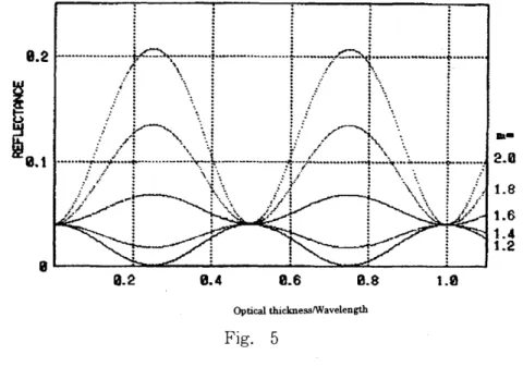
(13) 28. Memoirs of The School of B.O.S.T. of Kinki University No. 7 (2000). ~n,2 _k,2 -Sin 2<t>2 -2n,k,i. P,=~~================. ~n,2 -k/ -Sin 2<t>2 -2n,k,i. -~no2 -k 0 2 -Sin 2<t>2 - 2n okoi +~no2 -k 02 -Sin 2<t>2 - 2n okoi. (34). (33) and in a similar way, P 1 results in (34). Again, Fresnel coefficient P l, P 2 for p polarization is as follows. P 2 is expressed by (35) and in a similar way, P 1 results in (36). Reflectance of film with monolayer c'an be obtained from P2. COS cP I - OICOS cP 2 = ---'--'----"cos <PI + OICOS cP 2 I~ 2. .. V nl - SIn. 2", ~2 '" '1-'2 - nl COS '1-'2. I~ 2 . 2", ~2 '" vnl -sln'l-'2+nlcos'l-'2 ~(nl -kli)2 -sin 2<p2 -(nl -kli)2 cos <P2. ~(nl-kli)2 -sin 2<p2 +(nl-k,i)2COScP2. PI. (35). (nl-kli)Z~n02 -k 02 -sinZcP2 -2nokoi (nl -kli)2~n02 -k0 2-sin 2cP2 -2nokoi -(no -koi)2~nI2 -k 12 -sin 2cP2 -2nlkli +(no -koi)2~nI2 -k 12 -sin 2cP2 -2nlkli. (36). (32),-.,(36) formula. In particular, in the case of light incidence perpendicular to film with no light absorbing, Fresnel coefficient of reflection results in (37) n1 -no Pl=-n +no. (37). 1. derived from (33), (34), (35), (36) formula without discriminating sand p polarization. Fig. 5 displays the graph of reflectance value as a function of ns d / A for various nl value in the case of ns = I, no =1.5. Fig.3 interface 1 (1), interface 2 (2) Fig.5 optical thickness/wavelength (1).
(14) 29. 8.2. 1Il-. 2.0. 1.6 1.4. 1.2 I~------~~----~------~--~--~------~~. 0.2. 0.4. B.8. 0.6. 1.0. Optical thicknesslWavelength. Fig. 5. 2 - 4. Film with multilayer In the following, reflectance of film with multilayer consIstmg of layers over two is considered. In the case of film with mutilayer consisting of N layers as. nN+I. - - - - -......-------PN+I-------/--9 rN nN. PN. Fig.. -----/-r. N _1. 6. shown in Fig. 6, amplitude reflectance rl by first layer is expressed by the following formula derived from (31) formula. Assuming the first layer as single bour.dary with reflectance (effective Fresnel coefficient) expressed by (31).
(15) 30. Memoirs of The School of B.O.S.T. of E:inki University No. 7 (2000). P 2 + P1exp(-i 0 1 ) r1 = 1+P 2P1eXp(-i 0 1) r = P3 + P1exp(- i. O 2 ) 2 1+ P 3 P 1eXP(-1 O 2 ). (38). formula, reflectance by second layer is expressed by (38). By proceeding this procedure in succession to the layer with highest rank, reflectance of film with multilayer can be obtained. Therefore, the formula of amplitude reflectance by j-. OJ) rj = 1+Pj+1Pj_1eXp(-i OJ) P j +1 +P j_1exp(-i. (39). th layer results in (39). The formula of energy reflectance is expressed by (40) derived from (39) formula. Here the definition of ro, a , (3 ,a', b' is as follows. R. =r- xr.* = Pj+1 +~exp(-i a j ) J J J 1+ P j+l ~R j-l exp(- i a j ) Pj+1. +~exp(i. xl + pj+l~RH exp(i Pj+1Pj+l + cos. =. aj). an. O:~(Pj+l + Pj+l ~xp(i /3). 1+ cos o:~R j-l (p j+l"+ pr+l ~xp(i /3). +i.sino:~(pj+l-Pj+l~xP(i /3)+ Rj-lexp(2i /3). , 16 n;2 d 2{ 2 k2 . 2 ) a = -A 2 - j \n j - j-Sln cP j + 1 .. '. (40). (41). 3. Calculation of reflectance by deposited aluminum film 3 - 1. Oxida tion and reflectance of aluminum Metals which are used in spectrometer and diffraction grating, have a property of high reflectance over wide range of wavelength. Natural reflectance R is described using refractive index nand exctinction coefficient k characteristic of the material (medium), and incidence angle if>. However, because n,k has dependence on wavelength, in spite of high reflectance in wavelength zone of visible light and infrared light, reflectance is approximately low in wavelength zone of ultravoilet light and most of metals is extremely low in wavelength zone of extreme ultraviolet light. Drastic decrease of n,k in wavelength zone with.
(16) 31. photon of high energy causes it. Aluminum is cheap and therefore, an extremely important optical material, but reflection of deposited aluminum film decreases due to transformation of aluminum to aluminum oxide by oxidation proceeding with time in air. Because this oxidation proceeds more rapidly under the atmosphere with higher content of water vapor, this film has to be stored under dry air or vacuum chamber. However reflectance of reflection mirror and diffraction grating of aluminum which is used in wavelength zone of extreme ultraviolet light decrease due to gradual oxidation of the surface by residue gas such as hydrogen, oxygen and water etc. in chamber in spite of storing all the time in vacuum chamber. This reflectance decrease is remarkable especially in wavelength zone of extreme ultraviolet light compared with decrease in wavelength zone of visible light and ultraviolet light. This is considered to be caused by absorption edge around 10 eV corresponding to wavelength of 1240 A of aluminum oxide formed on surface. This aluminum oxide is transparent in wavelength zone of visible light and therefore, even in this oxide formation on the surface of deposited film, this oxide does not affect the transparency in wavelength zone of visible light. Similar thing is found even in measured data in experimental system in our laboratory. The reflectance of film decreases even in measuring the reflectance immediately after producing deposited aluminum film because aluminum oxide has already been formed on the aluminum surface. The reason for it is that deposited aluminum film is exposed to air during the process of attaching deposited film to equipment of measuring reflectance even if evaporated aluminum is deposited in high vacuum. In measuring surface reflectance of such a film, the reflectance decreases with time and after exposed in air, the reflectance reached the same with reflectance of aluminum oxide after about five days. To protect this oxidation, a method of depositing magnesium fluoride as coating film after depositing aluminum or a method of depositing lithium fluoride is used, but the reflectance still decreases gradually due to formation of oxidized film.. 3 - 2. Modeling of surface oxidation of deposited aluminum film By the reason described in 3 - 1., in this paper, considering that layer of aluminum oxide becomes thicker accompanying with the oxidation proceeding on the surface of aluminum, reflectance change caused by surface oxidation of aluminum was modeled by considering the film with multilayer as shown in the following and calculated result by computer was compared with experimental data. Oxidation process of deposited aluminum film is assumed as shown in the following. 1 . In the oxidized state in a certain degree of aluminum which proceeds from the surface, the nearest surface layer to the interface consists of only aluminum oxide. 2. Oxidation can be considered to occur in uniform medium with flat surface assuming postulated flat plane with parallel surfaces for the surface of oxidized aluminum. 3. Postulated film with two layers is considered for the oxidized state of aluminum. Second layer - only aluminum oxide.
(17) 32. Memoirs of The School of B.O.S.T. of Kinki University. No. 7 (2000). First layer - mixing of aluminum oxide and aluminum Substrate - only aluminum Table.. 1. Oxidation rate (%) Index of refraction n Oxidation rate (%) Index of refraction n. 0 5 10 15 20 25 30 35 40 45 50. 0.061 0.086 0.190 0.542 0.826 1.042 1.223 1.382 1.524 1.655 1. 775. 55 60 65 70 75 80 85 90 95 100. 1.886 1.989 2.084 2.173 2.256 2.332 2.403 2.468 2.527 2.582. n change accompanying wi th oxidat ion. 4. Because extinction coefficient of aluminum differs little from one of aluminum oxide, k = 0.950 is assumed and this value is used independent of oxidation rate. Values in Table.1 are used for n values with oxidation rate, too. 5. Thickness of aluminum oxide film in the surface layer Increases with proceeding of oxidation Reflectance of deposited aluminum film is calculated with mentioned above assumptions. 3- 3. Calculation of reflectance Energy reflectance R2 of film with two layers (Fig. 7) is expressed by (42) from. nl. -ik,. Fig.. 7.
(18) 33. R. P3 P; + COS a.JR;(P3 + P; ~XpO (3) : 1+ cos a.JR;{P3 + P; ~XpO (3) + i· sin aF,(P3 - P; ~xpO (3)+ R,exp(2 i (3). '.. 2. (42). ~i,sina.JR;{P3 -P;~xpO (3)+P3P;R,exp(2i (3). the above assumption. Here the definition of a, /3 ,a', b'. ex. =H(Ja 2+ b'2 +a') , J3=iH(Ja'2 + b'2 -a') , 16 n;2 2(2 2 . 2) a =-2-d2 \n2 -k2 -sin cJ>3 ' A. Amplitude reflectance p reflectance P, =. P3. 3. ,32 n;2. gIven by (43).. , 2. b = - - d 2 n2k2 A2. (. 43). for s polarization results in (44) and amplitude. cos<p, -~n,' -k,' -sin'<p, -2n2k2i 2 COS<P3 +~n/ -k/ -sin <p 3 -2n2k2i. = ~n/ -k22 -s i n2<p3 ~n/. IS. (44). 2n2k2i - {n/ -k22 -2n2k2i~os <P3 2 -k/-sin <p3 -2n2k2i +{n/ -k/-2n2k2i~oS<P3. (45). P 3 for p polarization results in (45). Reflectance of film with two layers can be calculated from (42),(43),(44),(45) formula. Some calculated values are shown in Fig. 8 .. z: 100 P::] x : I NCI DENCE [deg] y : THICKNESS (d2). z: REFLECTANCE [%] WAVELENGTH=1000 d 1 =10 n=1.0, k=O n=2.2, k=0.5 1.1 -,.. 100. :x: ,0{deqJ. n=1.5, k=0.5 n=O.5, k=0.5. Fig.. 8- 1.
(19) 34. Memoirs of The School of B.O.S.T. of Kinki University No. 7 (2000). z: 100 [\] .1:.::::::·::··: .::;~:. ....""'....'" ..... ....................,........... . ". ..................................................... . ~l il~I;-;lili1;jt;I~;~i;f! ! i l l:l~. x : INCIDENCE [deg] y : THICKNESS (d2). z: REFLECTANCE [%J WAVELENGTH=1000. d 1 =10 n=1.0, k= 0. n=2.0, k=0.5 n=1.5, k=0.5. 100. n=0.5, k=0.5. :x:. Fig. 8 - 2. z: 100£::\]. x : INCIDENCE [deg] y : THICKNESS (d2). z: REFLECTANCE [%J WA VEL ENG T H = 1000 d 1 =10. ·n=1.0, k= 0 n=1.B, k=O.5 n=1.5, k=0.5. 100 ~. n=0.5, k=0.5. ..',' .. .X.•. 0[deoJ. Fig. 8 - 3. 4. Result A calculated result following the procedure described in 3 - 2. is shown in Fig. 9. This is calculated a result for film with two layers consisting of aluminum.
(20) 35. z: 100[%]. x: INCIDENCE [deg] ~: THICKNESS'(d2). z: REFLECTANCE. P;]. WAUELENGTH=100 0~d2~30. (STEP 0.2). d1=1 n=l n=2.582-0. 950 i. ".-. x ... .-",.. n=0.190-0.950i. 0[deg]. n=0~061-0.946i. Fig. 9 - 1. x: INCIDENCE [degJ ~J: THICKNESS'(d2). z:REFLECTANCE IrJAUELENGTH= 100 0~d2~30. (STEP 0.2) d1=1 n=l .... - .... - .. ....... ,. y. n=2.582-0.950i. ,,1-. x ... n=0.826-0. 950 i n=0. 061-0. 946i. o[deg] Fig. 9 - 2. [%].
(21) 36. Memoirs of The School of B.O.S. T. of Kinki University No. 7 (2000). z: 100 [%J x: INCIDENCE [deg] ~J:. THICKNESS (d2). z: REFLECTANCE. [~;]. I~Al)ELENGTH= 100. 0~d2~30. (STEP 0.2) dl=l. n=l n=2. 582-0.950 i x··' 0tdeg]. n=1.223-0.950i n=0.061-0.946i. Fig. 9 - 3. z: 100 [%J x: INCIDENCE [degJ ~J: ,',. "'.. "';, .,:., . . . . ~~~~~i~~~~~~~~·. THICKNESS (d2). z:REFLECTANCE [%] I~Al)ELENGTH=100. 0~d2~30. (STEP 0.2) dl=l. n=l n=2. 5S2-0. 950i x .". ",.. n=1.524-0.950i n=0.061-0.946i. o[deg] Fig. 9 - 4.
(22) 37. z: 100 [%J. x: INCIDENCE [deg] ~J:. THICKNESS (d2). z: REFLECTANCE. [~'~J. I,~AUE LENGTH= 100. 0;£d2;£30 (STEP 0.2) d1=1 n=1 .... _---. ~. "'". n=2.582-0.950i ",. x .'. n=1.775;...0.950i. o[degJ. n=0.061-0. 946 i. Fig. 9 - 5. z: 100 [%J x: INCIDENCE [deg] ~J:. THICKNESS (d2). z:REFLECTANCE [%J ~~AlJELENGTH=100. 0;£d2;£30 (STEP 0.2) d1~1. n=1 ......... _"'". ~. n=2.582-0.950i ",. , x .'. n=1.989-0.950i. o[degJ. n=0.061-0.946i. Fig. 9 - 6.
(23) 38. Memoirs of The School of B.O.S.T. of Kinki University No. 7 (2000). z: 100 [%J x: INCIDENCE [deg] ~J:. THICKNESS (d2). z: REFLECTANCE. [~~]. INAIJELENGTH= 100 0~d2~30. (STEP 0.2). d1=1 n=l ....... . "' .• y ~. n=2. 582-0.950 i )(. .. -. n=2,173-0,950i n=0.061-0, 946 i. o[degJ Fig. 9 - 7. z: 100U~]. ;::~:--~~:-,~~~~.~.---------.-~.---.----------------. ._----y---------------------------.. - .......... ... - ...- ......... x: INCIDENCE [degJ !,J: THICKNESS (d2). z:REFLECTANCE [%]. .". WAIJELENGTH=100 0~d2~30. (STEP 0.2). d1=1 n=l ., ...... ,..• y. n=2,582-0. 950 i x .'. n=2,332-0.950i n=0,061-0.946i. o[degJ. Fig. 9 - 8.
(24) 39. z: 100[%] x: INCIDENCE [deg] ~J: THICKNESS (d2). z:REFLECTANCE [%] 1,,)AUELENGTH=100 0~d2~30. (STEP 0.2). dl=l n=l n=2.582-0.950i X···. n=2. 468-0. 950 i n=0.061-0.946i. 0[deg). Fig. 9 - 9. oxide and layer of aluminum oxide with oxidation rate of 10,...... 90 % in which layer thickness is 1nm in average in the interface, after aluminum oxide layer formed on deposited aluminum film. Wavelength of light incidence is 100nm. In graph, incidence angle is expressed on x axis and angle increases to 90 in a direction of from ahead toward back. Film thickness of nearest layer to the surface is expressed on y axis and reflectance (maximum 100%) is expressed on z axis. In Fig.10, a calculated results for film with single layer where aluminum 0. z: 100[~:;]. x:INCIDENCE [de9] ~):. TH I O~NESS (d). z: F:EFLECTANCE UJ ...... ........ 1"lAUE LENCiTH= 100. ...... 0~d~30. ....... ..... (STEP 0.2). .. , . .......................... ......... ". ~,J. n=l ........ n=2.582-0.950i n=0. 0E; 1-0. Sl4r3 i. 0[deg]. Fig. 10.
(25) 40. Memoirs of The School of B.O.S.T. of Kinki University No. 7 (2000). oxide layer formed on deposited aluminum layer is shown. Wavelength of light incidence is100nm. Again, Fig. 12 displays x-z graph in the case of 12A,13A and 20A film thickness. In Fig. 11, experimental data of reflectance measurement after left in atmosphere for 0,24 and ·1?0 hour are shown Fig. 9 - 1 reflectance of first layer with oxidation rate 10% (1) Fig. 9 - 2 reflectanc·e of first layer with oxidation rate 20% (1) Fig. 9 - 3 reflectance of first layer with oxidation rate 30% (1) Fig. 9 - 4 reflectance of first layer with oxidation rate 40% (1) Fig. 9 - 5 reflectance of first layer with oxidation rate 50% (1) Fig. 9 - 6 reflectance of first layer with oxidation rate 60% (1) Fig. 9 - 7 reflectance of first layer with oxidation rate 70% (1) Fig. 9 - 8 reflectance of first layer with oxidation rate 80% (1) Fig. 9 - 9 reflectance of first layer with oxidation rate 90% (1) Fig.10 reflectance in. the case of aluminum oxide formation on deposited aluminum film (1) . Fig.11- 1 reflectance of deposited aluminum film (1) Fig .11- 2 reflectance of deposited aluminum film after 24 hour (1) Fig.11- 3 reflectance of deposited aluminum film after 120 hour (1) Fig.12- 1 x-z graph in the case of film thickness 12 A in Fig.10 (1) Fig.12- 2 x-z graph in the case of film thickness 13 A in Fig.10 (1) Fig.12- 3 x-z graph in the case of film thickness 20 A in Fig.10 (1) 1~--~~--~--~---P------------~--~----. 0=0.542 k=0.950. 30. EIJ. IN:IIl3a [degl. Fig. 11-1.
(26) 41. IfCIIEM:E [degl. Fig. 11- 2 1~----r---~--~--~~--~--~--~----~--~. n=2.332 k=0.950. IfCJ~. [deal. Fig. 11- 3.
(27) 42. Memoirs of The School of B.O.S.T. of Kinki University No. 7 (2000). 1~--~--------~--~--~--~--~--~--~. I. ./. I i ! : : i i i ! I I ," ·-·_····t·_·_-i--_·_+-········..i-·_··..·_+_·_·····i-··.._·4····..·····S--.j.··j iii iI II II 1/ I i i ! Il Iii iii i R·{ ....·-··_+···-·_··.··-_·_+-·····..·-i·····_···+···_·····.i.••••- ...-+.......~!.i-.-....-. I ii I! I i i1..-.,/ I! Ii! ! i ! i I I ! ! /f I -·········+----···t·--··-+-··..······t··-··-·-t··-·-··t·-"G._+....-.-.....- ..- .. i ! : !: i i i I ! i: ! I. n=B.826 k=0.95B. j l i : i i i .-........+-.... _.-.-......-+-..- ....-1--......--+•..- .....1.....- ..4 ......._.1-._._.... ! I : ! : I i I. j. !. ". i I. I i. Iii I ! I. i. I. I I. 1N:IIEIl: [degl. Fig. 12- 1. n=B.826 k=B.960. IfCIIBCE [deg]. Fig. 12- 2.
(28) 43. 1~------------~--~~--~----------------I. I. I. Ii.. :. I. •. •. -.-..-t----i---..-~---i--·-··-+--··i--·-·........--·i-··-....'" iii i I ! i i:. I. Iii. iii. I'. iii ! i.' .....--..t._.......!t··_-........! ·_._··t········.-r---··t··.······_#·····-····· ..··01·_··· i. --JI. -J-LJ-.-l--.L.-kt-I ! I ! ! ~I ·-··-·..·t·-·-----;·---··--. --·--t-···-----t----·-··r-···--···r-·-----t----·----. I i ! I II I I i I. !. :. !. !. :. !. IN:IJE(E [degl. Fig. 12- 3. 5. Consideration In every graph, total reflectance decreases with Increase of film thickness in nearest layer of aluminum oxide to the surface and decrease with vibration because of taking the interference into account. When film thickness of nearest layer to the surface is large enough, the reflectance becomes constant and it is found that the value approaches the reflectance of pure aluminum oxide. It is in agreement with general experimental results that with proceeding of oxidation, the reflectance approaches the reflectance of pure aluminum oxide. When the oxidation rate of aluminum oxide in first layer is between 10 and 40 %, the reflectance with film thickness of nearby 0 ---15 nm decreases sharply, but the reflectance decreases gradually when the oxidation rate of aluminum oxide in first layer is between 50 and 90 %. It is considered that this occurs because mixed layer of aluminum and aluminum oxide serves as light absorption layer. In the case of contact of two mediums at the boundary plane, the reflectance at boundary plane becomes higher with higher refractive index of medium in light incidence side, but it is considered that with proceeding of oxidation of first layer, total reflectance decreases due to small difference of refractive index between two mediums because the refractive index of first layer approaches one of aluminum oxide.· The result that above calculation results was numerically in agreement with experimental result, could not be obtained. Fig.10 displays a calculated result of film with monolayer where aluminum oxide layer is formed on the aluminum deposited film. Reflectance decreases with vibration in accordance with change of film thickness in a similar way with the reflectance change in two layers model. However, the periodicity is very shorter than one in two layers model. In fact, such a change was observed in experimental data. Fig.11 displays experimental data and from this graph, it is found that gradual.
(29) 44. Memoirs of The School of B.O.S.T. of Kinki University No. 7 (2000). oxidation follows after instant oxidation in the atmosphere. Fig.12 is x-z graph in Fig.10 with film thickness of 12)\, 13)\,20)\. It is found that from this graph and Fig.11, the thickness of oxidized film is about 12""""13)\, 24 hour after it is exposed to the atmosphere and 120 hour later it becomes above about 20)\. Deposited aluminum film is oxidized to oxidized film with thickness in the order of 10 )\ at the moment when it is exposed to the atmosphere. In this paper, it was assumed that the half of medium was oxidized, but it is found that such a thing does not occur. 6. Conclusion. In this paper, deposited aluminum film was treated from a macroscopic viewpoint and therefore, the formation process of thin film could not be grasped. It is thought that in discussion of a relation between oxidation rate and reflectance, viewing material structure closely associated with experiment and considering the oxidation process with statistical treatment of each atom are needed. Conceptual film with two layers was assumed also, but calculating the reflection with treating aluminum oxidation as the changing system of refractive index and exctiction coefficient toward a depth direction with certain function form like changing system of oxidation rate toward a depth direction in fact seems to corresponds to calculating the near real reflection. It is found too that aluminum oxide is formed with film thickness of about 12""""13 )\ in the initial state of deposited aluminum film..
(30) 45. rw~~t';;Jj[~~1J't~OJSJZ{TSJZrni~c 7).tJ.T c" rw~OJ7't~ft-J't~j[ 'i-~~C.z- OJ7't~JE~. (JffifJT$ n". 1~~1*~ k). 5tti*~ ~ ~. c". ~j!J[ d ~c d:. "'? -C -~ft-J ~c ~ i. d: '5 tJ.m~~ ~ "'? -c~" .z- OJ -lf1. ~ 0 ~j!J[;O:Gl'~jf~~~ ~. A';Os7'tOJ1Bt:I~Jcl:t«-c+5tIj\ ~ t 't~!r@J~c 'i". t';;Jj[~7't~ft-J ~C~;O) tJ.SJZrrSJZrni~~cii: ~~;t -c7't~ft-J,t~j[~~tlfT ~. [!!]8~". ;t ~ c.. .z- OJ* ~ ~ ;Os7'tOJ1Btft~cl:t«-c1mm~ ~ ~t~d5'~C 'i". c. c ;os~ ~ ~o. ~rniOJ. t';;Jj[tJ.~rni~OJffft~cii: ~~. c;Os ~ ~ ~ 0. ~~~OJ7't~~tlfOJ1Jm'i Rouard 0*~~ 'Y. 7. AmC ;Os~ ~o. :,; l::0_ 7":'; A" 7 r'. ~. 'Y. 1*~~fflt' ~1Jmc ~. 7't~1. r. I). <m~~ tL -C ~ t:.o .z- tL ~c 'i~5<:i.J 7. ~Cif§~T ~ OJ~" ~~~OJ~tlfti~. c. C. ~ ti". :J:';. l::0.:1. -. r. I) 'Y. 7 ~c d: ~ ~tlf~c{j!~IJtJ.~5<:i.J 7 v. 1tT~0. =- r; b ~~~ ti" c. OJd: '5 tJ.7)1/. ~. ~rni OJ ~1t ~C d: ~ ~1t 7. =- r; bOJ~1t~". c. c ti 4 ~ffijr@llm~rnI)1IJfi~T ~. 7 A OJ*i~>J<66 ~~tlf~c tJ. ~o. ~OJ~rni~1t~cf* '5 .&!t-f$OJ~1tOJ;fir~ -t- -r' )I/1t. 7 )1/ ~. v*,)1/. 7 :,; A OJm'E~~~ATtLt-;f'" ~~~OJ7't~~tlf~c~~@I1m. OJ5t:ffJJE~@IImOJIE~~~m;Os:i&1~~ ~ ~o rw~~*td ~. c. c. "'? t:. ~". *'. )1/1*~~ ffl t '". L". MfJT~tlf~{T"'?. )1/ ~. =- r; b. 7)1/ ~. =- r; b~~. t:.o. OJj::JJJt ~C d: ~ 7't~ft-J't~j[ ti~. ~~~;Os~JJJt~ tL~ ~OJ. c c i;;t -c~tlf~~7)..
(31)
図

関連したドキュメント
Solutions of integral equa- tions are expressed by the inverse operators of auxiliary exterior and interior boundary value problems, i.e., theorems on the solvability of
Abstract The representation theory (idempotents, quivers, Cartan invariants, and Loewy series) of the higher-order unital peak algebras is investigated.. On the way, we obtain
We show that for a uniform co-Lipschitz mapping of the plane, the cardinality of the preimage of a point may be estimated in terms of the characteristic constants of the mapping,
Then it follows immediately from a suitable version of “Hensel’s Lemma” [cf., e.g., the argument of [4], Lemma 2.1] that S may be obtained, as the notation suggests, as the m A
In place of strict convexity we have in this setting the stronger versions given by the order of contact with the tangent plane of the boundary: We say that K ∈ C q is q-strictly
Abstract The classical abelian invariants of a knot are the Alexander module, which is the first homology group of the the unique infinite cyclic covering space of S 3 − K ,
In section 4, we consider another boundary controllability problem for the higher order linear Schr¨ odinger equation, in which only the value of the first spatial derivative (at x =
One important application of the the- orem of Floyd and Oertel is the proof of a theorem of Hatcher [15], which says that incompressible surfaces in an orientable and
