Development of an ISPH-FEM Weak Coupling Analysis System for 3-dimensional
Fluid-Structure Interaction Problems
M
ASAOO
GINO*, T
AKUYAI
WAMA**, M
ITSUTERUA
SAI*** * Information Technology Center, Nagoya University, Aichi** Graduate School of Informatics, Nagoya University, Aichi *** Faculty of Engineering, Kyushu University, Fukuoka
1. INTRODUCTION
To prevent and mitigate related disasters in the coastal area, a numerical simulation of tsunami-induced forces on structures is of great importance. For a 3-dimensional tsunami run-up and inundation simulation, mesh-free particle methods, such as the smoothed particle hydrodynamics (SPH) method1),2)
and the moving particle semi-implicit (MPS) method3), have been widely used. To improving numerical
stability of particle methods, the stabilized incompressible SPH (ISPH) method has been proposed using a relaxing the density invariance condition4). Moreover, to improving a parallel efficiency, a combination
of a hierarchical bucket-based domain decomposition and a dynamic load balancing for the explicit MPS This paper focuses on a weak coupling analysis system of 3-dimensional
fluid-structure interaction problems. As the numerical discretization scheme, the stabilized incompressible smoothed particle hydrodynamics (ISPH) method is adopted for fluid dynamics involving free surface flow and the finite element method (FEM) is used for structural dynamics. To save cost in software developments maintenance, the open source software is utilized. Especially, a general-purpose finite element analysis system, named ADVENTURE_Solid, and a general-purpose coupling analysis platform, named REVOCAP_Coupler, are employed. Moreover, techniques of an interface marker on the fluid-structure boundary and a dummy mesh for a fluid analysis domain is adopted to solve the problem that the REVOCAP_Coupler performs to unify two or more grid-based method codes. To verify a developed system, the dam break problem with an elastic obstacle is demonstrated. Moreover, the effect of a relaxation parameter in the ISPH method is studied.
(E-MPS) method, which adopts a pseudo-compressibility approach5), has been proposed6). On the other
hand, the finite element method (FEM) is a powerful tool for structures. The ADVENTURE system is well-known open source FEM software7).
In this research, we consider developing a partitioned coupling analysis system for fluid-structure interaction (FSI) problems such as tsunami-induced forces on structures. To solve FSI problems, a coupling analysis of a particle-based method and a grid-based method has been investigated. A coupling technique of SPH and FEM has been applied to FSI problems involving free surface flows8),9). A coupling
technique of E-MPS and FEM has been investigated for the interaction problem between an elastic structure and free surface flows10),11). However, since most of these are developed as a function-specific
application software, its approach is lack versatility. Hence, to save cost in software developments and maintenance, this research attempt to utilize the open source software. The REVOCAP_Coupler is an open source and a general-purpose coupling analysis platform12). Since the REVOCAP_Coupler performs
to unify two or more codes of a grid-based method, an interface marker on the fluid-structure boundary and a dummy mesh for a fluid analysis domain are proposed as SPH-FEM coupling techniques. With these techniques, a partitioned coupling analysis system with an in-house ISPH code, the ADVENTURE, and the REVOCAP_Coupler, is developed. Using a developed system, to verify a developed system, the dam break problem with an elastic obstacle is demonstrated, and the result is compared with the results calculated by other methods. Moreover, the effect of a relaxation parameter in the ISPH method is studied by the numerical experiments.
2. INCOMPRESSIBLE SPH METHOD FOR FLUID FLOWS 2.1. GOVERNMENT EQUATIONS
Let us consider the Lagrangian formulation of the incompressible Navier-Stokes equation and the continuity equation, 𝐷𝐷𝐯𝐯 𝐷𝐷𝐷𝐷 = − 1 𝜌𝜌0∇𝑃𝑃 + 𝜈𝜈∇ 2𝐯𝐯 + 𝐠𝐠 , (1) ∇ ⋅ 𝐯𝐯 = 0 , (2)
where 𝐯𝐯 is the flow velocity vector, 𝐷𝐷 the Lagrangian derivative operator, 𝑃𝑃 the pressure, 𝜌𝜌0 an
initial density, 𝜈𝜈 the coefficient of the kinematic viscosity, and 𝐠𝐠 the gravity vector. In incompressible fluid, the density is assumed to be constant.
2.2. PROJECTION METHOD
To solve incompressible Navier-Stokes equations, the projection method13) is applied. As the
predictor step, an intermediate velocity 𝐯𝐯∗ is explicitly calculated from (1) by ignoring the pressure
𝐯𝐯∗ = 𝐯𝐯𝑛𝑛+ Δ𝑡𝑡(𝜈𝜈𝛻𝛻2𝐯𝐯𝑛𝑛+ 𝐠𝐠) , (3)
where 𝐯𝐯𝑛𝑛 is the previous velocity at time 𝑛𝑛 and Δ𝑡𝑡 is the time increment width. As the corrector step,
the current velocity 𝐯𝐯𝑛𝑛+1 at time 𝑛𝑛 + 1 is obtained by correcting the intermediate velocity,
𝐯𝐯𝑛𝑛+1 = 𝐯𝐯∗+ Δ𝐯𝐯∗ = 𝐯𝐯∗− Δ𝑡𝑡 �1 𝜌𝜌0𝛻𝛻𝑃𝑃
𝑛𝑛+1� . (4)
To calculate (4), the current pressure value is needed. In the incompressible fluid, the pressure 𝑃𝑃𝑛𝑛+1 at
time 𝑛𝑛 + 1 is evaluated by 𝐯𝐯𝑛𝑛+1−𝐯𝐯∗ Δ𝐷𝐷 = − 1 𝜌𝜌0𝛻𝛻𝑃𝑃 𝑛𝑛+1 . (5)
The key point of the projection method is the way to evaluate the current pressure. Thus, by using Tait equation, the pressure 𝑃𝑃𝑛𝑛+1 is also calculated explicitly. On the other hand, the pressure can be evaluated
by solving a pressure Poisson equation arising from (5). The former scheme is called an explicit method, and the latter is a semi-implicit method. In this research, the semi-implicit approach is adopted.
2.3. A STABILIZED ISPH METHOD
By keeping divergence-free condition14),15), a pressure Poisson equation is constructed by
⟨𝛻𝛻2𝑃𝑃𝑛𝑛+1⟩ =𝜌𝜌0
Δ𝐷𝐷⟨𝛻𝛻 ⋅ 𝐯𝐯∗⟩ , (6)
where bracket 〈𝜙𝜙〉 denotes SPH approximation of a function 𝜙𝜙 by summation of contributions from neighbor particles
𝜙𝜙(𝑥𝑥𝑖𝑖) ≈ 〈𝜙𝜙𝑖𝑖〉 = ∑𝑗𝑗𝑚𝑚𝜌𝜌𝑗𝑗𝑗𝑗𝑊𝑊��𝑥𝑥𝑖𝑖 − 𝑥𝑥𝑗𝑗�, ℎ�𝜙𝜙𝑗𝑗 , (7)
where 𝑚𝑚𝑗𝑗 is a representative mass at particle 𝑗𝑗, 𝜌𝜌𝑗𝑗 is density related to particle 𝑗𝑗, 𝑊𝑊 denotes a
smoothing kernel function, 𝑥𝑥𝑗𝑗 is position vector of particle 𝑗𝑗, and ℎ is smoothed length. As the
alternative scheme, a pressure Poisson equation can be constructed by keeping density-invariance condition16),17),
⟨𝛻𝛻2𝑃𝑃𝑛𝑛+1⟩ =𝜌𝜌0−⟨𝜌𝜌∗⟩
Δ𝐷𝐷2 , (8)
where 𝜌𝜌∗ is an intermediate density. The main difference between both schemes is appeared in the source
term of the pressure Poisson equation. Note that this keeping density-invariance scheme is analogous to the formulation in the MPS, although the MPS utilizes the number of particles instead of the density.
To improve the accuracy of the results of SPH method in incompressible flow, the uniform particle distribution should be kept. Thus, a stabilized ISPH method has been proposed by adding the different source term derived from the particle density4),
⟨𝛻𝛻2𝑃𝑃𝑛𝑛+1⟩ =𝜌𝜌0
Δ𝐷𝐷⟨𝛻𝛻 ⋅ 𝐯𝐯∗⟩ + 𝛼𝛼
𝜌𝜌0−⟨𝜌𝜌𝑛𝑛⟩
Δ𝐷𝐷2 , (9)
where 𝛼𝛼 ∈ [0,1] is a relaxation parameter and 𝜌𝜌𝑛𝑛 is the previous particle density.
Moreover, for the large eddy simulation, the Smagorinsky turbulence model is implemented into the ISPH method. The turbulence model gives the stable flow and pressure profile compared to the stabilized ISPH18).
3. SPH-FEM COUPLING ANALYSIS SYSTEM
3.1 A PARTITIONED COUPLING ANALYSIS SYSTEM
In this research, we consider developing a partitioned coupling analysis system for FSI problems. To solve FSI problems, a coupling analysis of a particle-based method such as the SPH method and a grid-based method such as the FEM has been investigated. However, since most of the related works are developed as a function-specific application software, its approach is lack versatility. Hence, to save cost in software developments and maintenance, the open-source software is utilized. Note, however, that the particle-based method is a fast-growing field, and a mature software for fluid dynamics is little or none. Therefore, an in-house code is used as an ISPH method.
The ADVENTURE system is an open source and general-purpose computational mechanics system and designed to be able to analyze a model of arbitrary shape with tens or more million degrees of freedom mesh. The ADVENTURE system has a module-based architecture, and the ADVENTURE_Solid performs for elastic-plasticity. To solve a geometric nonlinearity, the total Lagrangian formulation and the updated Lagrangian formulation are implemented. The Newmark’s 𝛽𝛽 method19) is adopted as the time
integration scheme.
The REVOCAP_Coupler is an open source and a general-purpose coupling analysis platform. The REVOCAP_Coupler unifies two or more arbitrary single dynamics phenomenon analysis software among fluid, solid, a magnetic field, thermal, and sound. Exchanging physical quantities between the different topology of the mesh is applied. Moreover, this software performs one of the two or bi-directional weak coupling analysis and bi-directional semi-strong coupling analysis by an iterative partitioned type solution. Note that the REVOCAP_Coupler is designed to unify software based on a grid-based method.
3.2 FSI COUPLING MODEL
In this research, a numerical simulation system for the FSI problems is developed by coupling an implicit FEM and the semi-implicit ISPH method. In this case, a similar time increment width of the structure analysis can be used for the fluid analysis. Thus, a partitioned coupling system based on the conventional serial staggered (CSS) scheme20) is adopted. In the present research, the fluid-structure
interaction problem at a time step is calculated without iterative refinement, that is the weak coupling analysis. A predicted value of the displacement for the fluid analysis and a surface traction for the structure are calculated by the REVOCAP_Coupler.
3.3 CONFIGURATION OF ISPH-FEM COUPLING MODEL
In here, the REVOCAP_Coupler cannot be used for the purpose of this research because it performs to unify two or more codes of a grid-based method. To solve this issue, an interface marker and a dummy mesh are proposed.
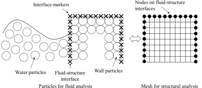
Interface markers are generated on fluid-structure boundaries. To represent adequate deformation of structure and save steps to consider the spatial distribution of interface markers, the position of interface markers for the ISPH method is determined by the nodes on surface mesh for the FEM. The configuration of particles and a mesh is illustrated in Fig. 1. In the ISPH code, the pressure at the interface marker is calculated from values of neighboring particles based on the SPH approximation. Using this technique, the different spatial resolution between the ISPH method and the FEM is easily used.
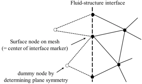
A dummy mesh is constructed in fluid analysis domain as shown in Fig. 2. A dummy mesh is generated by plane, that is fluid-structure boundaries, symmetry. The main role of the interface marker is to calculate values on fluid-structure boundaries. Therefore, the information of mesh involving surface nodes is only used. Moreover, the information of surface nodes of a dummy mesh can be utilized for determining above interface markers.
Fig. 1 The configuration of ISPH-FEM model. Interface markers for the ISPH method are located at the same position as nodes on surface mesh for the FEM.
Water particles Wall particles
Interface markers
Fluid-structure interface
Nodes on fluid-structure interfaces
Fig. 2 Dummy mesh generation for fluid analysis domain. Dummy mesh for the ISPH method is determined symmetrically by fluid-structure boundaries.
4. NUMERICAL EXPERIMENTS 4.1 A DAM BREAK PROBLEM
To verify a developed system, the dam break problem21) with an elastic obstacle is demonstrated. The
initial configuration is illustrated in Fig. 3. Material properties and analysis conditions are shown in Table 1. The elastic obstacle is modeled by 29,000 linear tetrahedral elements for the FEM, where geometric nonlinearity is considered by the total Lagrangian formulation. The number of surface nodes is about 4,500, and the average of the element-edge length is 0.0046 m. A convergence criterion of the Newton-Raphson method for solving the nonlinear equation is 1.5 × 10⁻⁶ and the criterion of the conjugate gradient
method for each step is 1.0 × 10⁻⁶. To avoid an unwanted increase in amplitude values at the high
frequencies, a numerical damping is considered in the Newmark’s 𝛽𝛽 method with 𝛽𝛽 = 0.6 and 𝛾𝛾 = 0.3025. For the ISPH method, the water column, wall boundary, and the elastic obstacle are discretized by about 0.9 million particles in total. The size of the particle is 0.003 m. The pressure Poisson equation is solved by the incomplete Cholesky conjugate gradient method and its convergence criterion is 1.0 × 10⁻³. The relaxation parameter 𝛼𝛼 = 0.1 is the same as an optimum value for a 3-dimensional dam
break problem with a rigid obstacle4).
In the present research, the same time increment width is used for both the ISPH method and the FEM. The supercomputer of SGI UV2000, which consists of Intel Xeon E5-4650 (8-core, 2.7 GHz), is used for the computation.
Dummy mesh of fluid analysis for the REVOCAP_Coupler Surface node on mesh
(= center of interface marker)
dummy node by determining plane symmetry
Mesh of structural analysis Fluid-structure interface
Fig. 3 Dam break problem with an elastic obstacle (units: cm).
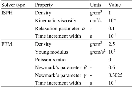
Table 1 Material properties and analysis conditions in an ISPH of fluid analysis and a FEM of structural analysis.
Solver type Property Units Value
ISPH Density g/cm3 1
Kinematic viscosity cm2/s 10-2
Relaxation parameter 𝛼𝛼 - 0.1
Time increment width s 10-4
FEM Density g/cm3 2.5
Young modulus g/cm/s2 107
Poisson’s ratio - 0
Newmark’s parameter 𝛽𝛽 - 0.6
Newmark’s parameter 𝛾𝛾 - 0.3025
Time increment width s 10-4
4.2 COMPARISON WITH OTHER SCHEMES
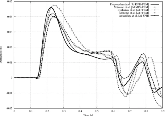
The results as shown in Fig. 4 is the deflection of the upper-left corner of the elastic obstacle. The numbers of MPI processes for fluid, structure, and coupler are 4, 4, and 8, respectively. The average computation timings of time steps are 1.98 seconds for the fluid, 2.07 seconds for the structure, and 0.014 seconds for the coupler. As can be seen in Fig. 5, the calculation result is compared with the results calculated by the 2D particle FEM22), the 2D particle FEM23), the 2D SPH method24), and a coupling of
the 2D E-MPS method and the 2D FEM10). The result of the coupling of E-MPS and FEM is calculated
by a weak coupling scheme based on CSS. The results of the particle FEM and the SPH are from a fully coupling-based analysis. The left upper corner of the obstacle shows a small deflection to the left, that is negative deflection when the water acts on its lower part. And then, the elastic obstacle is deformed to the
14.6 1.2 29.2 58.4 29.2 8.0obstacle water column wall boundary depth: 29.2
right, that is positive deflection, while the water rises. The results of the present research show good agreement with other results.
Fig. 4 Deflection of an elastic obstacle. The results are compared with the results calculated by other methods.
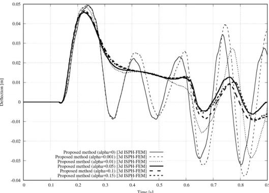
4.3 EFFECTS OF RELAXATION PARAMETER
Determining an efficient relaxation parameter in the source term of the pressure Poisson equation is of great importance. The incompressible flow means the effects of pressure by particle density are zero or negligible. However, the particle methods might show pressure fluctuations due to numerical density variations. Hence, the second term on the right-hand-side of (8) make improvements in such numerical stability. Moreover, the effect of additionally source term based on the particle density is increased due to the increase in the relaxation parameter. In Fig. 5, results with different relaxation parameters are plotted. A relaxation parameter of 𝛼𝛼 = 0 denotes to construct the source term of the pressure Poisson equation by only divergence-free condition. No experimental results have found in this example, but the elastic obstacle of results with 𝛼𝛼 = 0 and 𝛼𝛼 = 0.001 show artificial oscillation because of particle leakage. On the other hand, results with 0.01 or larger in 𝛼𝛼 improve particle leakage through a moving wall boundary and have good agreement with other results in Fig. 4.
The results with 𝛼𝛼 = 0.05 and 0.1 for 3.0 seconds are obtained in Fig. 6. From this figure, our developed system succeeded in a long-term calculation with adequate results compared to other numerical discretization schemes.
Fig. 5 Deflection of an elastic obstacle. The results are compared with different relaxation parameters.
Fig. 6 Deflection of the elastic obstacle with a relaxation parameter α = 0.05 or 0.1.
5. CONCLUSIONS
In the present research, a partitioned coupling analysis system based on the CSS scheme is developed for solving fluid-structure interaction problems involving free surface flows. As the numerical discretization scheme, the stabilized ISPH method is adopted for fluid dynamics, and the
large-deformation FEM is used for structural dynamics. For saving cost in software developments and maintenance, this research utilizes the general-purpose open source software of the ADVENTURE_Solid and the REVOCAP_Coupler. To verify a developed system, the dam break problem with the elastic obstacle is solved. As the results, our system provides good agreement with the results calculated by other methods. Moreover, by numerical experiments, adequate relaxation parameter in the ISPH method and the effect of numerical damping are obtained.
ACKNOWLEDGEMENTS
This research is partially supported by Ring! Ring! project of JKA Public Interest Incorporated Foundation Grant Number 28-148. This research is also partially supported by JSPS KAKENHI Grand Number 17H02829. The authors would like to thank the ADVENTURE project for providing us a development version of the ADVENTURE_Solid. This research used computational resources of the HPCI system provided by (the names of the HPCI System Providers) through the HPCI System Research Project (Project ID: hp150154). Numerical experiments were performed by the supercomputer at the Information Technology Center, Nagoya University.
REFERENCES
1) Lucy, L.B., “A numerical approach to the testing of the fusion process,” Astronomical Journal, 88 (1977), pp.1013–1024.
2) Gingold, R.A. and Monaghan, J.J., “Smoothed particle hydrodynamics: theory and application to non-spherical stars,” Monthly Notices of the Royal Astronomical Society, 181 (1977), pp.375–389.
3) Koshizuka, S. and Oka, Y., “Moving-particle semi-implicit method for fragmentation of incompressible fluid,” Nuclear Science and Engineering, 123 (1996), pp.421–434.
4) Asai, M., Aly, A.M., Sonoda, Y. and Sakai, Y., “A stabilized incompressible SPH method by relaxing the density invariant condition,” Journal of Applied Mathematics, 2012 (2012), p.139583.
5) Shakibaeinia, A. and Jin, Y.C., “A weakly compressible MPS method for modeling of open boundary free surface flow,” International Journal for Numerical Methods in Fluids, 63 (2010), pp.1208–1232. 6) Murotani, K., Koshizuka, S., Tamai, T., Shibata, K., Mitsume, N., Yoshimura, S., Tanaka, S.,
Hasegawa K., Nagai, E., and Fujisawa, T., “Development of hierarchical domain decomposition explicit MPS method and application to large-scale tsunami analysis with floating objects,” Journal
of Advanced Simulation in Science and Engineering, 1 (2014), pp.16–35.
7) Yoshimura S., Shioya R., Noguchi H. and Miyamura T., “Advanced general-purpose computational mechanics system for large-scale analysis and design,” Journal of Computational and Applied
Mathematics, 149 (2002), pp.279–296.
8) Yang, Q., Jones, V. and McCue, L., “Free-surface flow interactions with deformable structures using an SPH-FEM model,” Ocean Engineering, 55 (2012), pp.136–147.
9) Fourey, G., Oger, G., Touz´e, D. L. and Alessandrini, B., “Weak coupling strategy between FE and SPH methods for FSI simulations,” Int. Conf. Violent Flows, (2012), pp.205–212.
10) Mitsume, N., Yoshimura, S., Murotani, K. and Yamada, T., “MPS-FEM partitioned coupling approach for fluid-structure interaction with free surface flow,” International Journal of
Computational Methods, 11 (2014), p.1350101.
11) Mitsume, N., Yoshimura, S., Murotani, K. and Yamada, T., “Parallel analysis system for fluid-structure interaction with free-surface using ADVENTURE_Solid and LexADV_EMPS,” Advances in Computational Fluid-Structure Interaction and Flow Simulation, Springer International Publishing, (2016), pp.245–255.
12) Yoshimura, S., Yonemura, N. and Yamada, T., “Coupling Analysis Platform in Parallel Environments REVOCAP_Coupler,” Proceedings of APCOM2007, (2007).
13) Chorin, A.J., “Numerical solution of the Navier-Stokes equations,” Mathematics of Computation, 22 (1968), pp.745–762.
14) Cummins, S. and Rudman, M., “An SPH projection method,” Journal of Computational Physics, 152-2 (1999), pp.584–607.
15) Lee, E.-S., Moulinec, C., Xu, R., Violeau, D., Laurence, D. and Stansby, P., “Comparisons of weakly compressible and truly incompressible algorithms for the SPH mesh free particle method,” Journal of
Computational Physics, 227-18 (2008), pp.8417–8436.
16) Khayyer, A., Gotoh, H. and Shao, S., “Corrected incompressible SPH method for accuratewater-surface tracking in breaking waves,” Coastal Engineering, 55-3 (2008), pp.236–250.
17) Khayyer, A., Gotoh, H. and Shao, S., “Enhanced predictions of wave impact pressure by improved incompressible SPH methods,” Applied Ocean Research, 31-2 (2009), pp.111–131.
18) Asai, M., Aly, A.M., Sonoda, Y., “ISPH-FEM coupling simulator for the FSI problems,” Proceeding
of the 6th SPHERIC SPH workshop, (2011), pp.201–208.
19) Newmark, N. M., “A method of computation for structural dynamics,” J. Eng. Mech. Div., 85 (1959), pp.67–94.
20) Farhat, C. and Lesoinne, M., “Two efficient staggered algorithms for the serial and parallel solution of three-dimensional nonlinear transient aeroelastic problems,” Comput. Methods Appl. Mech. Eng., 182 (2000), pp.499–515.
21) Walhorn, E., Kölke, A., Hübner, B. and Dinkler, D., “Fluid-structure coupling within a monolithic model involving free surface flows,” Comput. Struct., 83 (2005), pp.2100–2111.
22) Idelsohn, S.R., Marti, J., Limache, A. and Oñate, E., “Unified Lagrangian formulation for elastic solids and incompressible fluids: Application to fluid-structure interaction problems via the PFEM,”
Comput. Methods Appl. Mech. Engrg., 197 (2007), pp.1762–1776.
23) Ryzhakov, P. B., Rossi, R., Idelsohn, S. R. and Oñate, E., “A monolithic Lagrangian approach for fluid–structure interaction problems,” Comput. Mech., 46 (2010), pp.883–899.
24) Amanifard, N., Hesan, M. and Rahbar, B., “An SPH approach for fluid-hypoelastic structure interactions with free surfaces,” Proceedings of the World Congress on Engineering, (2011).