Testable Design of Sequential Circuits with Improved Fault Efficiency
Debesh K. Das Bhargab B. Bhattacharya Satoshi Ohtake & Hideo Fujiwara Dept. of Comp. Sc. & Engg. ACM Unit Graduate School of Information Science Jadavpur University Indian Statistical Institute Nara Institute of Science and Technology Calcutta - 700 032, India Calcutta - 700 035, India Nara 630-0101, Japan
[email protected] [email protected] {satosi-o, fujiwara}@is.aist-nara.ac.jp
Abstract: A new synthesis and design-for-testability (DFT) technique is proposed for improving fault efficiency in non-scan synchronous sequential circuits. Certain simple constraints are imposed on state encoding prior to synthesis, and then a DFT technique is employed that guarantees absence of all sequentially undetectable faults, such as invalid, equivalent and isomorph. If the netlist is available instead of state description, only the DFT technique is applied, by skipping the synthesis part. The proposed design guarantees significantly lower test generation time, higher fault coverage, and almost complete fault efficiency, when sequential test generation tools are used. Experiments on MCNC and ISCAS 89 benchmark circuits show encouraging results. Hardware overhead of the proposed method compares favorably with that of full-scan.
1. Introduction
To reduce the complexity of test generation in sequential circuits, several attempts were made to achieve testable design, or to synthesize them for ensuring high testability. Full-scan techniques reduce the test generation problem for a sequential circuit to a combinational one [1]. The area overhead associated with full-scan can be reduced by adopting partial scan [2]. The main problem with scan techniques is that they may fail to allow at-speed testing. To overcome the shortcomings of scan techniques, non- scan approaches are proposed [3-7]. However, the presence of sequentially undetectable faults makes test generation in non-scan circuits very complex. Combinational ATPG was used in [6, 7], along with certain DFT methods to obtain complete fault efficiency. The ratio of the number of faults detected or proved redundant by a test algorithm, to the total number of faults in a circuit, is called fault efficiency. Several techniques for removal of undetectability and redundancy in sequential circuits appeared earlier in [9-14].
To improve fault efficiency in non-scan synchronous sequential circuits, we propose a new technique, based on removal of sequential undetectability. If the state transition graph (STG) is available, we use certain constraints on state encoding to synthesize the machine that ensures detection of invalid faults. We then employ a DFT technique [5] using some additional logic that guarantees absence of other sequentially undetectable
faults such as, equivalent and isomorph. For large circuits, where only netlist is available instead of STG, we skip the synthesis part, and apply DFT technique only. Removal of these undetectable faults significantly lowers test generation time, and enhances fault efficiency when sequential ATPG is used, as evident from experimental results on several benchmarks circuits. Our approach is simple, and hardware overhead compares favorably with that of full-scan.
2. Preliminaries
We assume the classical stuck-at fault model. A gate-level combinational circuit is said to be irredundant if all faults, single or multiple, are detectable by input- output experiments. Let the given synchronous sequential machine be denoted by M. Assume that M has l primary input lines x1, x2,…, xl, and m primary output lines Z1, Z2,…, Zm. The outputs y1, y2,…, yk of k flip-flops define the present state of the machine. The inputs Y1, Y2,…, Yk
to the memory elements at time t determine the values of yi’s at t+1, and define the next state of M. A sequential machine M can be described as a quintuple: M ={I, O, S, δ, Z}, where I, O, S are finite, nonempty sets of inputs, outputs, and states, respectively; δ: I × S → S, is the state transition function; Z: I × S → O, is the output function. A differentiating sequence (DS) of a pair of states Si and Sj, is a minimal-length sequence of input vectors, such that the output response obtained by applying the sequence when the circuit is initially in Si, is different from that obtained when the circuit is initially in Sj [16]. Two states are said to be equivalent, if they do not have a DS.
A machine is in synchronization mode, if the operation starts with a specified input sequence, referred to as power-up sequence [17]. Hardware reset may exist as a special input. Under this mode, the starting or reset state is a state in which the machine starts, after using power-up sequence or hardware reset. A state is called a valid state if it can be reached from the reset state by applying an input sequence, otherwise it is an invalid state. A machine is said to be operated in free mode, if no restriction on the power-up sequence exists; the machine 14th International Conference on VLSI Design, pp. 128-133, January 3-7, 2001.
may start operation at the state it happens to be in that time. Let us consider a fault f in the machine M, and let the faulty machine be denoted by Mf ={I, O, Sf, δf, Zf}. Two states Si in M and Sif in Mf are called corresponding states, if they have the same encoding [8]. States Si and Si f
are called corresponding equivalent states, if they produce identical response to any input sequence. The machine M is assumed to be in synchronization mode with hardware reset if the STG description of M is available, otherwise it is assumed be in free mode.
3. Redundancy and undetectability
Though the concepts of redundancy and undetectability are synonymous in combinational circuits, they differ in sequential circuits [17, 18] where a fault may be irredundant, but undetectable. A fault f is said to be detectable in a sequential circuit if, for every pair of initial states S in M and Sf Mf, there exists an input sequence X, such that response Z(X,S) of M to X, is different from the response Zf(X,Sf) of Mf at some time unit on some output [17]. A fault is said to be undetectable if it is not detectable.
Definition: A fault in a sequential circuit M is said to be combinationally redundant if starting from any input state with any sequence of input vectors, its effect cannot be observed at the primary outputs, or by only probing next state lines, i.e., they are undetectable under full-scan. Definition: If a fault is not combinationally redundant, but changes the state diagram such that no input sequence starting from any state, can detect the change, then the fault is sequentially redundant fault (SRF).
SRF's are broadly classified into three groups under the synchronization mode [15].
Definition: If a fault changes the transitions only from the invalid states, but does not corrupt any transition from the valid states, it is an invalid fault. An equivalent fault is a fault that causes an interchange and/or creation of equivalent states only. A fault in a sequential machine is an isomorph fault if the state table of the faulty machine is identical to that of the fault-free machine under renaming (i.e., some permutation) of the states.
3.1 Equivalent fault
If an equivalent fault causes an interchange of equivalent states alone, then it is undetectable under both synchronization and free mode while testing with single or multiple observation time approaches. However, some equivalent faults caused by creation of new states (and interchange) may be detectable as a probabilistically detectable fault [23].
Lemma 1 [5]: If for all Si (0< i <2k-1), Z{Ia,Si} is distinct from Z{Ia,Sj} i≠j for at least an input Ia∈I, then an equivalent fault can never exist regardless of the circuit
realization (that uses k flip-flops). 3.2 Isomorph fault
An isomorph fault is generally undetectable under both synchronization and free mode with single or multiple observation time approaches. However, some isomorph faults may be detectable, if the machine operates in synchronization mode [19].
3.3 Invalid fault
This can occur only in synchronization mode. Lemma 2: If an invalid fault appears, then there exist at least an invalid state Si and one input Ia∈I, such that
(i) δf{Ia,Si} ≠δ{Ia,Si}, or Zf{Ia,Sif}≠Z{Ia,Si} or both and
(ii) ∀Ia∈I, δf{Ia,Sj
f}=δ{Ia,Sj} and Zf{Ia,Sjf}=Z{Ia,Sj} if Sj is a valid state, where, Si and Sif (similarly Sj and Sjf) are corresponding states.
Corollary 1: If all 2k states are valid in the machine, an invalid fault cannot occur.
Next, we present a design technique that eliminates three types of SRFs from a sequential circuit. 4. Testable design
Given a sequential circuit M {I, O, S, δ, Z} with l inputs, m outputs, and k flip-flops. First, we assume that the STG of M is available. We then synthesize a modified machine M' {I, O, S', δ', Z'} with a control input C, such that M' is devoid of redundancy and easily testable. Further, M' reduces to M when C = 0.
4.1 Synthesis for detecting invalid faults
We assume that the number of invalid states in M can be at most 2k-1 -1. Now, we impose a simple restriction on the state assignment of the machine.
4.1.1 State-assignment: We assume that all the invalid states are encoded such that the state variable y1 is assigned logic value 1. Since the number of invalid states
< 2k-1 -1, this can always be done. The remaining bits may be assigned arbitrarily. With this constraint, we synthesize the sequential circuit without any restriction on its structure; then we augment the circuit with some extra logic as indicated in the following procedure.
4.1.2 Circuit design: To detect invalid faults, all states are made valid by adding a 2-input OR gate and a control input C in the test mode. We change the next-state function Y1 to Y1' as: Y1' = Y1 + C. Only one next-state function is modified (Fig. 1). The output functions are then changed by augmenting the circuit with an additional combinational logic Cadd according to a DFT method described in subsection 4.2.
Theorem 1: The modified circuit M' is devoid of all invalid faults.
Proof: The encoding of any invalid state in M begins with y1 =1. Consider an invalid state Sinv in M with the code (1, y2*, y3*,....,yk*) where yi* ∈ (0,1), for 2 < i < k. Obviously, there exists a valid state Sv whose code is (0, y2*, y3*,....,yk*). As Sv is a valid state, in the original machine M, there exists a valid state S* ∈ S and an input Ia∈ I, s. t. δ{Ia, S*}= Sv. Then in the modified machine M', the following conditions are true: for C = 0, δ'{Ia, S*}
= Sv and for C = 1, δ'{Ia, S*}= Sinv. Thus, the invalid state Sinv in M becomes valid in M'. So an invalid fault can never occur in M'.
4.2 DFT to remove equivalent and isomorph faults For eliminating equivalent and isomorph faults, we use an additional logic Cadd as in [5]. If the STG is available, we adopt this procedure following the technique described in subsection 4.1. If only netlist is known, then we skip the encoding part, and apply this DFT technique alone to the circuit. In that case, the machine is considered to be in free mode, without the necessity of using a reset line. Three cases may arise.
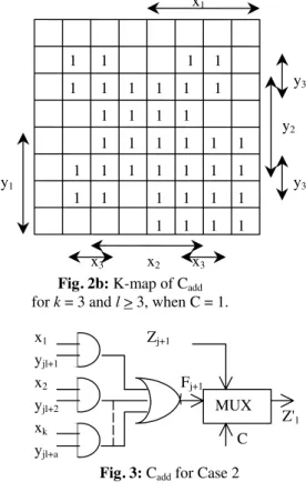
Case 1 (k < l): Consider only one output line, say Z1 of M. Then modify it as Z1' = CZ1 + CF, where C is the same control input used earlier, and F = {x1 y1+ x2y2+...+ xkyk} (Fig. 2a). The other functional outputs are kept unchanged. For every combination of (y1, y2, ...., yk),
yi ∈ (0,1), the sub-function consists of a unique sum term of {xi's}. The K-map of F for k = 3 is shown in Fig. 2b. Variables xi's (yi's) are used to label the map horizontally (vertically). No two rows (i.e., states) in the map have identical patterns.
Hardware overhead: Cadd requires (3k+6) gate inputs. Case 2 (l < k < l ×m): This is similar to Case 1, but needs slight modification. Let r = k / l. Modify output lines Z1, Z2,.... Zr as: Zj+1' = CZj+1 + CFj+1, where, 0 < j < r-1, C is a control input and Fi realized by a two- level AND-OR circuit (Fig. 3) has the following expression: Fj+1 = x1yjl+1+ x2yjl+2+ ……+xayjn+a where a = l for (0<j<r-1), and a=k-(r-1)n for j = r-1. If a is found to be 1, then we replace Fj+1 by yjl+1.
Hardware overhead: In general, Cadd requires (3k+ 6r) gate inputs, for (k mod l) = 1, this value is (3k+6r-3).
Case 3 (l ×m < k) : The proposed technique does not fit in this case. We however, observe that this case seldom appears among benchmarks.
Theorem 2 [5]: The modified circuit is devoid of all equivalent and isomorph faults.
Theorem 3 [5]: The differentiating sequence for every pair of states in M' is of unit length.
Besides removing sequential redundancies, our technique has an added advantage. As the differentiating sequence for any pair of states is of unit length in our design, sequential test generation time reduces drastically. This is highly desirable for inducing testability [24].
x1
y1
F
Fig. 2a: Cadd for l > k (Case 1) C
Z'1
MUX x2
y2
xk
yk
Z1
x1
x2 x3
x3
y1
y2
y3
y3
Fig. 2b: K-map of Cadd
for k = 3 and l > 3, when C = 1. x1
yjl+1
Fj+1
Fig. 3: Cadd for Case 2 C
Z'1
MUX x2
yjl+2
xk
yjl+a
Zj+1
Fig. 1: Testable design for detection of invalid, equivalent, and isomorph faults Additional
combinational logic Cadd
Combinational circuit
y1
yk
xl
x1 Z1
Zm
Y1
Yk
FF
FF
Z'1
Z'm
C
Global reset
1 1 1 1 1 1 1 1 1 1 1 1 1 1 1 1 1 1 1 1 1 1 1 1 1 1 1 1 1 1 1 1 1 1 1 1 1
The use of only a single OR gate transforms all invalid states to valid states in test mode. Thus, it becomes easier for a sequential ATPG to initialize the machine to a desired state during test generation. As a result, test generation time is reduced, and fault efficiency is increased. We performed our experiments on MCNC [20], as well as on ISCAS 89 [21] benchmarks.
# # # # extra gate
of of of in p u ts n am e P Is P O s FFs D FT fu ll p ro p osed
l m k C ase sca n d esig n
b b a ra 4 2 4 1 2 4 2 0
b b sse 7 7 4 1 2 4 2 0
b b ta s 2 2 3 2 1 8 2 0
b eec ou n t 3 4 3 1 1 8 1 7
cse 7 7 4 1 2 4 2 0
d k 1 4 3 5 3 1 1 8 1 7
d k 1 5 3 5 2 1 1 2 1 4
d k 1 6 2 3 5 2 3 0 3 2
d k 1 7 2 3 3 2 1 8 2 0
ex1 9 1 9 5 1 3 0 2 3
ex2 2 2 5 3 3 0 N A
ex3 2 2 4 2 2 4 2 6
ex4 6 9 4 1 2 4 2 0
ex5 2 2 4 2 2 4 2 6
ex6 5 8 3 1 1 8 1 7
ex7 2 2 4 2 2 4 2 6
k eyb 7 2 5 1 3 0 2 3
k irk m an 1 2 6 4 1 2 4 2 0
lion 2 1 2 1 1 2 1 4
lion 9 2 1 4 3 2 4 N A
m c 3 5 2 1 1 2 1 4
op u s 5 6 4 1 2 4 2 0
p lan et 7 1 9 6 1 3 6 2 6
p lan et1 7 1 9 6 1 3 6 2 6
p m a 8 8 5 1 3 0 2 3
s1 8 6 5 1 3 0 2 3
s1 4 8 8 8 1 9 6 1 3 6 2 6
s1 4 9 4 8 1 9 6 1 3 6 2 6
s2 0 8 1 1 2 5 1 3 0 2 3
s2 7 4 1 3 1 1 8 1 7
s2 9 8 3 6 8 2 4 8 4 4
s3 8 6 7 7 4 1 2 4 2 0
s4 2 0 1 9 2 5 1 3 0 2 3
s5 1 0 1 9 7 6 1 3 6 2 6
s8 2 0 1 8 1 9 5 1 3 0 2 3
s8 3 2 1 8 1 9 5 1 3 0 2 3
sa n d 1 1 9 5 1 3 0 2 3
sse 7 7 4 1 2 4 2 0
styr 9 1 0 5 1 3 0 2 3
tav 4 4 2 1 1 2 1 4
tb k 6 3 5 1 3 0 2 3
tm a 7 6 5 1 3 0 2 3
tra in 1 1 2 1 4 3 1 8 N A
tra in 4 2 1 2 1 1 2 1 4
5. Experimental results
Comparison of hardware overhead of our design with that of full-scan in terms of additional circuit area estimated by the number of literals, is given in Tables 1 and 3. For most of these circuits, Case 1 of the proposed DFT fits well, and for some circuits Case 2 is appropriate.
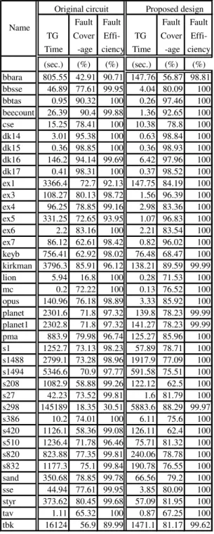
Fault Fault Fault Fault TG Cover Effi- TG Cover Effi- Time -age ciency Time -age ciency (sec.) (%) (%) (sec.) (%) (%) bbara 805.55 42.91 90.71 147.76 56.87 98.81 bbsse 46.89 77.61 99.95 4.04 80.09 100 bbtas 0.95 90.32 100 0.26 97.46 100 beecount 26.39 90.4 99.88 1.36 92.65 100 cse 15.25 78.41 100 10.38 78.8 100 dk14 3.01 95.38 100 0.63 98.84 100 dk15 0.36 98.85 100 0.36 98.93 100 dk16 146.2 94.14 99.69 6.42 97.96 100 dk17 0.41 98.31 100 0.37 98.52 100 ex1 3366.4 72.7 92.13 147.75 84.19 100 ex3 108.27 80.13 98.72 1.56 96.39 100 ex4 96.25 78.85 99.16 2.98 83.36 100 ex5 331.25 72.65 93.95 1.07 96.83 100
ex6 2.2 83.16 100 2.21 83.54 100
ex7 86.12 62.61 98.42 0.82 96.02 100 keyb 756.41 62.92 98.02 76.48 68.47 100 kirkman 3796.3 85.91 96.12 138.21 89.59 99.99 lion 5.94 16.8 100 0.28 71.53 100
mc 0.2 72.22 100 0.13 76.52 100
opus 140.96 76.18 98.89 3.33 85.92 100 planet 2301.6 71.8 97.32 139.8 78.23 99.99 planet1 2302.8 71.8 97.32 141.27 78.23 99.99 pma 883.9 79.98 96.74 125.27 85.96 100 s1 1252.7 73.13 98.23 57.89 78.71 100 s1488 2799.1 73.28 98.96 1917.9 77.09 100 s1494 5346.6 70.9 97.77 591.58 75.51 100 s208 1082.9 58.88 99.26 122.12 62.5 100 s27 42.23 73.52 99.81 1.6 81.79 100 s298 145189 18.35 30.51 5883.6 88.29 99.97 s386 10.2 74.01 100 6.11 75.6 100 s420 1126.1 58.36 99.08 126.11 62.4 100 s510 1236.4 71.78 96.46 75.71 81.32 100 s820 823.88 77.35 99.81 240.06 78.78 100 s832 1177.3 75.1 99.84 190.78 76.55 100 sand 350.68 78.85 99.78 66.56 79.2 100 sse 44.94 77.61 99.95 3.85 80.09 100 styr 373.62 80.45 99.68 57.09 81.95 100 tav 1.11 65.32 100 0.87 67.25 100 tbk 16124 56.9 89.99 1471.1 81.17 99.62 Original circuit Proposed design Name
Table 1: Hardware overhead for MCNC benchmarks: scan design vs. our method
Table 2: Test generation results for MCNC benchmarks
NA: not applicable
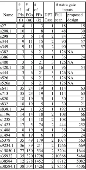
# # # # extra gate of of of inputs Name PIs POs FFs DFT Full proposed
(l) (m) (k) Case scan design
s27 4 1 3 1 18 15
s208.1 10 1 8 1 48 30
s298 3 6 14 2 84 72
s344 9 11 15 2 90 57
s349 9 11 15 2 90 57
s382 3 6 21 3 126 NA
s386 7 7 6 1 36 24
s400 3 6 21 3 126 NA
s420.1 18 1 16 1 96 54
s444 3 6 21 3 126 NA
s526 3 6 21 3 126 NA
s526n 3 6 21 3 126 NA
s641 35 24 19 1 114 63
s713 35 23 19 1 114 63
s820 18 19 5 1 30 21
s832 18 19 5 1 30 21
s838.1 34 1 32 1 192 102
s1196 14 14 18 2 108 66
s1238 14 14 18 2 108 66
s1423 17 5 74 2 444 252
s1488 8 19 6 1 36 24
s1494 8 19 6 1 36 24
s5378 35 49 179 2 1074 563
s9234.1 36 39 211 2 1266 669
s15850.1 77 150 534 2 3204 1644
s35932 35 320 1728 2 10368 5484
s38584 12 278 1452 2 8712 5082
s38584.1 38 304 1426 2 8556 4506
Very few of the benchmark circuits belong to Case 3, for which our technique is not applicable. We assume that a full-scan design with k latches requires k pieces of 2-input multiplexers, i.e., 6k gate inputs.
For MCNC circuits [20], where STGs are available, we first encode the states according to our proposed method, and then use AutoLogic II (Mentor Graphics) to synthesize the circuit for the original machine. With this circuit, we add only one OR gate with a control input as described in Section 4.1 to make all invalid faults of the original machine testable. Then we augment the circuit with some extra logic as discussed in Section 4.2. This removes all equivalent and isomorph faults. Test generation results (Table 2) show that our technique not only decreases test generation time, but also attains almost 100% fault efficiency in all cases.
TG Fault Fault TG Fault Fault Time Cover- Effici- Time Cover- Effici-
-age -ency -age -ency (sec. ) (%) (%) (sec. ) (%) (%)
s27 0.05 100 100 0.07 100 100
s208.1 1137.4 10.68 72.01 257.41 12.72 95.23 s298 141.2 90.12 98.15 7.13 91.77 100 s344 228.13 93.67 96.52 183.16 95.31 98.25 s349 171.68 94.26 97.7 140.23 94.54 97.91
s386 3.59 92.08 100 3.55 92.41 100
s420.1 3324.9 9.4 34.9 2597.7 11.14 50.49
s641 1.62 87.85 100 1.61 87.83 100
s713 1.48 84.1 100 1.73 84.31 100
s820 127.39 96.51 99.39 97.37 96.64 99.63 s832 134.26 95.61 99.16 101.7 95.71 99.64 s838.1 4546.5 8.8 51.69 4966.6 10.4 50.72
s1196 1.42 99.91 100 1.54 100 100
s1238 1.78 97.16 100 1.83 97.39 100
s1423 11422 49.76 52.64 5446.3 80.44 81.92 s1488 122.06 98.91 99.98 119.8 98.92 99.98 s1494 54.88 98.49 99.98 52.24 98.51 99.98 s5378 17784 71.5 76.47 14447 78.09 83.73 s9234.1 46211 10.42 55.63 68148 36.87 45.29 s15850.1 83676 44.71 58.75 65176 63.91 74.62 s35932 30873 89.6 99.34 6138.3 91.55 99.97 s38584 310757 24.35 48.77 149202 59.14 80.22
Original Circuit Proposed design Name
A significant improvement in test generation results can be observed with our technique for the circuit s298. Without any testable design, the fault efficiency is only 30.51%. Using our synthesis and DFT technique, fault efficiency reaches 99.97% (Table 2).
For ISCAS 89 [21] benchmarks, only netlists are available, and hence we use the DFT technique alone (Section 4.2), which eliminates all equivalent and isomorph faults. Further, test generation time is decreased to a large extent, as for every pair of states, there exists a differentiating sequence of unit length in test mode. The results are summarized in Table 4. In most of the cases, we observe higher fault coverage and improved fault efficiency. However, in some cases, our design requires higher test generation time and also attains lower fault efficiency. We have marked these cases by shaded area in Table 4. Addition of extra logic in our design ensures detection of more faults, some of which were possibly aborted during test generation in the original circuit; this might have caused an increase in test generation time. However, the sequential test generation tool detects more faults when DFT is incorporated, as evident from higher fault coverage observed in these cases.
The sequential ATPG TestGen (Sunrise) [22] is run on a SUN workstation, and AutoLogic II (Mentor Graphics) is used for synthesis.
Table 3: Hardware overhead for ISCAS 89 benchmarks: scan design vs. our method
Table 4: Test generation results for ISCAS 89 benchmarks
6. Conclusion
As redundancy and undetectability make test generation more complex in sequential circuits, we attempt to achieve high testability by removing undetectable faults in these circuits. We have proposed a novel and simple technique that differs significantly from the previous approaches to redundancy removal. For circuits with STG descriptions, we propose a simple encoding of states before synthesis, and then use a control input and some additional logic to make all invalid, equivalent and isomorph faults detectable. If only netlist is available for the circuits, we skip the synthesis part, and apply the DFT technique for removal of equivalent and isomorph faults. The additional logic is independent of the structure and functionality of the given machine, and depends only on the number of PI's, PO's and memory elements. Since there exists a unit- length differentiating sequence for every pair of states in the modified machine, the approach simplifies test generation, as evident from experimental results. A sequential ATPG needs less time for test generation, and achieves improved fault efficiency for most of the cases. The proposed method does not require a synthesis procedure involving computationally intensive search, and as a non-scan approach, it offers at-speed testing. Its hardware overhead compares favorably with that of full- scan designs.
References
1. M. Abramovici, M. A. Breuer, and A. D. Friedman, Digital Systems Testing and Testable Design. W. H. Freeman & Co., New York, 1990.
2. S. T. Chakradhar, A. Balkrishnan, and V. D. Agrawal, “An exact algorithm for selecting partial scan flip flops,” Proc., DAC, pp. 81-86, 1994. 3. V. Chickermane, E. M. Rudnick, P. Banerjee, and J.
H. Patel, “Non-scan design-for-testability techniques for sequential circuits,” Proc., DAC, pp. 236-241, 1993.
4. I. Pomeranz and S. M. Reddy, “Design for testability for sequential circuits using locally available lines,” Proc., DATE-98, p. 983-984, 1998.
5. D. K. Das and B. B. Bhattacharya, “Testable design of non-scan sequential circuits using extra logic,” Proc., ATS, pp. 176-182, 1995.
6. S. Ohtake, T. Masuzawa, and H. Fujiwara, “A non- scan DFT method for controllers to achieve complete fault efficiency,” Proc., ATS, pp. 204-211, 1998. 7. D. K. Das, S. Ohtake, and H. Fujiwara, “New DFT
techniques of non-scan sequential circuits with complete fault efficiency,” Proc., ATS, pp. 263-268, 1999.
8. I. Pomeranz and S. M. Reddy, “On identifying untestable and redundant faults in synchronous sequential circuits,” Proc., VTS, pp. 8-14, 1994.
9. M. A. Iyer, D. E. Long, and M. Abramovici,
“Identifying sequential redundancies without search,” Proc., DAC, pp. 457-462, 1996.
10. W. Cao and D. K. Pradhan, “Sequential redundancy identification using recursive learning,” Proc., ICCAD, pp. 56-62, 1996.
11. I. Pomeranz and S. M. Reddy, “On removing redundancies from synchronous sequential circuits with synchronizing sequences,” IEEE TC, vol. 45, no.1, pp. 20-32, Jan. 1996.
12. X. Lin, I. Pomeranz, and S. M. Reddy, “On removing redundant faults from synchronous sequential circuits,” Proc., VTS, pp. 168-175, 1998.
13. H. Yotsuyanagi and K. Kinoshita, “Undetectable fault removal of sequential circuits based on unreachable states,” Proc., VTS, pp. 176-181, 1998. 14. I. Pomeranz and S. M. Reddy, “On finding
undetectable and redundant faults in synchronous sequential circuits,” Proc., ICCD, pp. 498-503, 1998. 15. S. Devadas, H-K. T. Ma, A. R. Newton, and A.
Sangiovanni-Vincentelli, “A synthesis and optimization procedure for fully and easily testable sequential machines,” IEEE TCAD, pp. 1100-1107, Jan. 1989.
16. S. Devadas and K. Keutzer, “A unified approach to the synthesis of fully testable sequential machines,” IEEE TCAD, vol. 10, pp. 39-50, 1991.
17. I. Pomeranz and S. M. Reddy, “Classification of faults in synchronous sequential circuits,” IEEE TC, vol. 42, no.9, pp. 1066-1077, Sept. 1993.
18. M. Abramovici and M. A. Breuer, “On redundancy and fault detection in sequential circuits,” IEEE TC, pp. 864-865, 1979.
19. D. K. Das, U. K. Bhattacharya, and B. B. Bhattacharya, “Isomorph redundancy in sequential circuits,” IEEE TC, September 2000.
20. S. Yang, “Logic synthesis and optimization benchmarks user guide,” Technical Report 1991- IWLS-UG-Saeyang, Microelectronics Center of North Carolina, USA.
21. F. Brglez, D. Bryan, and K. Kozminski,
“Combinational profile of sequential benchmark circuits,” Proc., ISCAS, pp. 1929-1934, 1989. 22. Sunrise Test Systems, Inc., Sunrise Reference
manual Version 2.3, 1996.
23. I. Pomeranz and S. M. Reddy, and J. H. Patel,
“Theory and practice of sequential machine testing and testability,” Proc., FTCS, pp. 330-337, 1993. 24. A. Ghosh, S. Devadas, and A. R. Newton,
“Sequential test generation and synthesis for testability at the register transfer and logic levels,” IEEE TCAD, pp. 579-598, May 1993.