A Scheduling Method for Hierarchical Testability
Using Results of Test Environment Generation
Jun Nishimaki
Graduate School of Industrial Technology Nihon University
Chiba, JAPAN [email protected]
Toshinori Hosokawa College of Industrial Technology
Nihon University Chiba, JAPAN
Hideo Fujiwara Faculty of Informatics Osaka Gakuin University
Osaka, JAPAN [email protected]
Abstract—A binding method for hierarchical testability has been proposed to increase the number of testable functional units in hierarchical testing using behavioral level circuits [8]. The method aims to synthesize many functional units which can be tested by test sequences generated by hierarchical test generation. In this paper, we propose a scheduling method for hierarchical testability to increase efficiency of the binding method for hierarchical testability. Our proposed method assigns control steps to each operation based on the results of test environment generation to increase the effectiveness of the binding method. Experimental results show that combination of our proposed scheduling method and the binding method for hierarchical testability improves fault coverage by 11% on average in hierarchical testing.
Keywords—hierarchical test generation; test environments; behavioral synthesis; scheduling; binding
I. INTRODUCTION
Recent advances in semiconductor technologies have resulted in exponential increases in VLSI circuit density and complexity. As a result, test generation becomes more difficult. In particular, test generation for sequential circuits is difficult to achieve high fault efficiency in reasonable test generation time. Full-scan design [1] and automatic test pattern generator (ATPG) for combinational circuits are widely used to achieve high fault efficiency for single stuck-at faults. Efficient test generation methods have been proposed for combinational circuits [2-6]. These test generation methods can achieve high fault efficiency for scan designed sequential circuits. However, scan design increases hardware overhead such as area, delay, and power consumption. Moreover, long test application time in scan testing is a problem from the view point of test cost. To resolve these problems, efficient test generation methods for sequential circuits are required.
A hierarchical test generation method using behavioral level circuits has been proposed as an efficient test generation
method for sequential circuits [7]. This test generation method is efficient for circuits designed by behavioral synthesis, and generates test sequences for each operation in a control data flow graph (CDFG). In hierarchical testing using behavioral level circuits, test sequences generated for an operation op can test the functional unit that is assigned to op. In this paper, a functional unit which has test sequences generated by hierarchical test generation is referred to as a hierarchically testable functional unit, and a functional unit which does not have test sequences generated by hierarchical test generation is referred to as a hierarchically untestable functional units. It is important to increase the number of hierarchically testable functional units to achieve high fault coverage in hierarchical testing using behavioral level circuits.
A binding method for hierarchical testability has been proposed to increase the number of hierarchically testable functional units [8]. This binding method aims to test hierarchically untestable functional units by test sequences generated for other functional units.
Binding in behavioral synthesis is a process which is applied for scheduled CDFGs (SCDFG), and its solution space depends on the results of scheduling. Hence, it can be expected that the number of hierarchically testable functional units increases by performing scheduling for hierarchical testability.
In this paper, we propose a scheduling method for hierarchical testability to increase the number of hierarchically testable functional units in the binding method for hierarchical testability. The remainder of this paper is organized as follows. Section II describes a hierarchical test generation using behavioral level circuits. Section III describes the binding method for hierarchical testability proposed in [8]. A scheduling method for hierarchical testability is proposed in Section IV. Section V presents the
15th IEEE Workshop on RTL and High Level Testing (WRTLT'14), Nov. 2014.
experimental results. Finally, Section VI concludes this paper and discusses for future work.
II. HIERARCHICAL TEST GENERATION This section describes a hierarchical test generation method using behavioral level circuits. In hierarchical testing using behavioral level circuits, test sets for each operation in a CDFG are generated by gate-level combinational ATPG beforehand. A hierarchical test generation accelerates time to generate test sequences for each operation by using these test sets.
To apply test patterns to an operation op in a CDFG, it is necessary to propagate any test pattern from primary inputs of a CDFG to the inputs of op. Moreover, it is necessary to propagate any test response from the output of op to primary outputs of a CDFG. The path allowing any value to be propagated from a primary input to the input of op is referred to as a justification path, and the path allowing the any value at the output of op to be propagated to a primary out is referred to as a propagation path. A justification path and a propagation path are referred to collectively as a test environment.
A hierarchical test generation method tries to generate test environments for all operations in a CDFG. Test sequences are generated for operations with a test environment by substituting test patterns for test environments. On the other hand, a hierarchical test generation method cannot generate test sequences for operations without a test environment. In hierarchical testing using behavioral level circuits, test sequences generated for an operation op can test the functional unit that is assigned to op at functional unit binding. Hence, a functional unit which is assigned to at least one operation with a test environment is a hierarchically testable functional unit. On the other hand, a functional unit which is assigned to only operations without a test environment is a hierarchically untestable functional unit. If the number of operations with a test environment is less than the number of required functional units, hierarchically untestable functional units are synthesized. In [7], if hierarchically untestable functional units are synthesized, test multiplexers are inserted to an RTL data path to change hierarchically untestable functional units into hierarchically testable functional units. All functional units in an RTL data path become hierarchically testable functional units by inserting test multiplexers. However, the insertion of test multiplexers increases hardware overhead such as area, delay, and power consumption. Furthermore, additional primary inputs are required to control
test multiplexers during testing. A binding method for hierarchical testability has been proposed to increase the number of hierarchically testable functional units without the insertion of test multiplexers [8].
III. BINDING FOR HIERARCHICAL TESTABILITY This section describes the binding method for hierarchical testability proposed in [8]. This method aims to test hierarchically untestable functional units by test sequences generated for other functional units. Testing hierarchically untestable functional units by test sequences generated for other functional units is referred to as rescue.
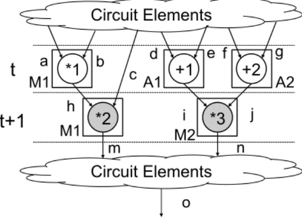
Fig. 1 shows an example of a SCDFG. In Fig. 1, white colored operations are ones with a test environment. On the other hand, gray colored operations are ones without a test environment. In Fig. 1, multiplication *1 and additions +1 and +2 are operations with a test environment. Multiplications
*2 and *3 are operations without a test environment. M1 and M2 represent multipliers assigned to multiplications, and A1 and A2 represent adders assigned to additions. Variable o is a primary output variable. In Fig. 1, since M1, A1, and A2 are assigned to operations with a test environment, these functional units are hierarchically testable functional units. On the other hand, since M2 is not assigned to a multiplication with a test environment, M2 is a hierarchically untestable functional unit. In Fig. 1, the number of multipliers required is 2. On the other hand, the number of multiplications with a test environment is 1. Hence, one multiplier becomes a hierarchically untestable multiplier.
The binding method for hierarchical testability proposed in [8] performs register binding to rescue hierarchically untestable functional units synthesized due to lack of the number of operations with a test environment.
Fig. 1 Example of SCDFG Circuit Elements
Circuit Elements
t
t+1
c h
m n
o M1
M1 M2
a b
i j
*1
*2 *3
+2
A1 +1 A2
d e f g
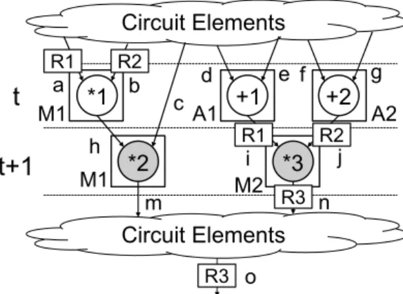
Fig. 2 shows an example of binding for hierarchical testability to rescue M2. In Fig. 2, R1, R2, and R3 represent registers assigned to variables.
Registers assigned to input variables of operations with a test environment are referred to as test pattern registers. In Fig. 2, R1 and R2 are assigned to a and b which are the input variables of multiplication *1 with a test environment. Hence, R1 and R2 are test pattern registers for M1. Test patterns for M1 are loaded to R1 and R2 at control step t.
The binding method for hierarchical testability proposed in [8] focuses on idle states of functional units. An idle state of a functional unit fu is explained as follows. If no operation that fu is assigned is executed at control step t, fu is in idle state at control step t. This binding method performs register binding to propagate test patterns from test pattern registers to inputs of hierarchically untestable functional units which are in idle state.
In Fig. 2, M2 is in idle state at control step t since no multiplication where M2 is assigned is scheduled at control step t. Hence, even if M2 performs the operation for hierarchical testing at control step t, there is no effect on the circuit function. If M2 can load data from R1 and R2 which are the test pattern registers for M1 at control step t, test patterns for M1 are propagated to the inputs of M2. In Fig. 2, R1 and R2 are assigned to i and j, respectively. Therefore, R1 and R2 are connected to the inputs of M2. The method proposed in [8] augments the RTL controller to supply control signals which allow data from R1 and R2 to be propagated to the inputs of M2 at control step t. As the result, test patterns for M1 can be propagated to the inputs of M2 at control step t.
Furthermore, the binding method for hierarchical testability proposed in [8] assigns primary output registers to output variables of hierarchically untestable functional units to observe test responses of hierarchically untestable functional units.
Fig. 2 Binding for Hierarchical Testability
In Fig. 2, R3 is a primary output register since R3 is assigned to the primary output variable o. R3 is also assigned to n which is the output variable of M2. Therefore, the output of M2 is connected to R3. The method proposed in [8] augments the RTL controller to supply control signals which allow data from the output of M2 to be propagated to R3 at control step t. As the result, test responses of M2 can be observed at o of control step t+1. The propagation of test patterns for M1 to the inputs of M2 is achieved, and observation for test responses of M2 is also achieved. Hence, M2 becomes a hierarchically testable functional unit.
IV. SCHEDULING FOR HIERARCHICAL TESTABILITY In this section, a scheduling method for hierarchical testability to increase the number of rescued hierarchically untestable functional units is proposed.
Scheduling in behavioral synthesis is a process which assigns control steps to each operation in CDFGs.
In general, scheduling algorithms in behavioral synthesis are classified into latency-constrained scheduling algorithms and resource-constrained scheduling algorithms.
Latency-constrained scheduling algorithms aim to minimize the number of functional units under a latency constraint. On the other hand, resource-constrained scheduling algorithms aim to minimize latency under constraints for the number of functional units. This paper focuses on latency-constrained scheduling algorithms.
The force directed scheduling (FDS) method has been proposed as an efficient latency-constrained scheduling method [9]. In our proposed scheduling method for hierarchical testability, first, FDS is performed to obtain the number of functional units and latency in FDS. The number of functional units and latency obtained by FDS are used as constraints in our proposed scheduling method. In this paper, we propose two scheduling strategies to increase the number of rescued hierarchically untestable functional units in the binding method proposed in [8].
A. Strategy for Idle States of Functional Units
We propose a scheduling strategy which takes idle states of functional units into account as the first strategy. As described in the previous section, the binding method proposed in [8] rescues hierarchically untestable functional units by using idle states of hierarchically untestable functional units. To rescue a hierarchically untestable functional unit fu by using an operation op with a test environment, fu must be in idle state at control step t which is assigned to op. The proposed Circuit Elements
Circuit Elements
t
t+1
c h
m n
o M1
M1 M2
R1 R2
R1 R2
R3
a b
i j
R3
*1
*2 *3
+2
A1 +1 A2
d e f g
scheduling method aims to increase the number of rescued hierarchically untestable functional units. Thus, it is important to increase the number of hierarchically untestable functional units which are in idle state at control steps assigned to operations with a test environment.
Fig. 3 shows an example of scheduling for hierarchical testability. In Fig. 3, a white colored operation is one with a test environment. On the other hand, gray colored operations are ones without a test environment. Only *8 is an operation with a test environment. Control steps are uniquely assigned to all operations except for *8 due to the latency constraint. The numbers of multipliers and adders obtained by FDS are 3 and 1, respectively. If control step t is assigned to *8, the number of required multipliers becomes 4 and violates a constraint for the number of multipliers obtained by FDS. Therefore, our proposed scheduling method cannot assign control step t to *8. Control steps which can be assigned to *8 are t+1, t+2, and t+3.
If control step t+1 is assigned to *8, the number of the multiplications where control step t+1 is assigned becomes 3. Hence, the number of the multipliers that execute multiplication at control step t+1 becomes 3. In other words, the number of the multipliers that are in idle state at control step t+1 is 0. Hence, the binding method proposed in [8] cannot rescue the hierarchically untestable multipliers. On the other hand, in Fig. 3, our proposed scheduling method assigns control step t+2 to *8. As the result, one multiplier is in idle state at control step t+2. Therefore, there is a possibility that one multiplier is rescued by the binding method proposed in [8].
As mentioned above, our first scheduling strategy aims to increase the number of hierarchically untestable functional units which are in idle state at control steps assigned to operations with a test environment.
B. Strategy for Test Pattern Registers
We propose a scheduling strategy which takes test pattern registers into account as the second strategy. As described in the previous section, the binding method proposed in [8] assigns test pattern registers to the inputs of hierarchically untestable functional units to rescue hierarchically untestable functional units. The proposed scheduling method aims to increase the number of rescued hierarchically untestable functional units. Thus, it is important to increase the number of variables where test pattern registers can be assigned. To achieve this goal, our second scheduling strategy aims to reduce the lifetime length of input variables for operations
with a test environment.
In Fig. 3, e and f are the input variables of *8 with a test environment. Hence, the test pattern registers for the multiplier are assigned to e and f. If control step t+3 is assigned to *8, the lifetimes of e and f overlap with those of the input variables of all multiplications without a test environment. Therefore, the test pattern registers for the multiplier cannot be assigned to the input variables of hierarchically untestable multipliers. Hence, the binding method proposed in [8] cannot rescue hierarchically untestable multipliers. On the other hand, in Fig. 3, our proposed scheduling method assigns control step t+2 to *8. As the result, the lifetimes of e and f are reduced and do not overlap with those of o and p. Therefore, the test pattern registers for multiplier can be assigned to o and p. Hence, there is a possibility that one multiplier is rescued by the binding method proposed in [8].
As mentioned above, our second scheduling strategy aims to reduce lifetimes of input variables of operations with a test environment.
V. EXPERIMENTAL RESULTS
Experiments were performed to evaluate the effectiveness of our proposed method. In the experiments, the hierarchical test generation using behavioral level circuits was performed for three circuits. To clarify the effectiveness of our proposed method, we compare two cases. In one case, the circuits are synthesized by using FDS and the binding method proposed in [8], and in the other case, the circuits are synthesized by using our proposed scheduling method and the binding method proposed in [8]. Design CompilerTM was used for logic synthesis. All of faults in the data paths and the controllers were evaluated in the experiments.
Fig. 3 Scheduling for Hierarchical Testability
t
t+1
t+2
*1 *2 *3
*4 *5
*6
+1
t+3
+2 +3
*7
*8
a 3 5 b c 5 3 d e f
g h i j
k m n
o p
q r
Table I shows the information of behavioral description for three circuits. In Table I, the “Circuit” column indicates the name of circuit. ARF is the auto regressive filter (ARF) from [10]. We designed two circuits named FIR+MPEG and DWT+MPEG to obtain large CDFGs. FIR+MPEG is the circuit that adds results of finite impulse response filter (FIR) [10] and results of MPEG motion vector (MPEG) [10]. DWT+MPEG is the circuit that adds results of discrete wave transformation (DWT) [10] and results of MPEG [10].
In Table I, the “#ADD” column and the “#MUL” column list the numbers of additions and multiplications, respectively. The “ADD with TE” column and the “MUL with TE” column list the numbers of additions with a test environment and multiplications with a test environment, respectively.
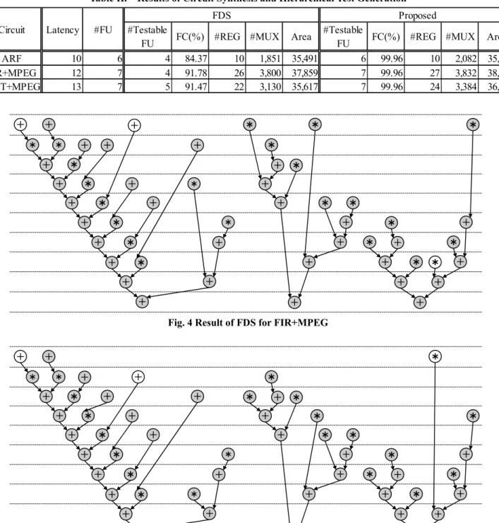
Fig. 4 and Fig. 5 show the results of FDS for FIR+MPEG and our proposed scheduling for FIR+MPEG, respectively. In Fig. 4 and Fig. 5, white colored operations are ones with a test environment. On the other hand, gray colored operations are ones without a test environment. Unfortunately, the scheduling results of ARF and DWT+MPEG are omitted due to page limitation.
Table II shows the results of circuit synthesis and the hierarchical test generation. In Table II, the “Circuit” column indicates the name of circuit. The “Latency” column lists the latency of circuit. The “#FU” column lists the number of functional units. The “FDS” column lists the results of FDS. The “Proposed” column lists the results of our proposed scheduling method. The “#Testable FU” column lists the number of hierarchically testable functional units. The “FC” column lists the fault coverage in the hierarchical test generation. The fault coverage was calculated by sequential fault simulator in TetraMAXTM by using test sequences generated by the hierarchical test generation. The “#REG” column lists the number of registers in the data path. The
“#MUX” column lists the total number of inputs of the multiplexer. Finally, the “Area” column lists the circuit area after logic synthesis. In the experiments, the bit width of data path was set to 32.
Our proposed scheduling method was performed under the latency constraint and the constraints for the number of functional units obtained by FDS. Hence, the latency and the number of functional units were the same as FDS.
In FDS, hierarchically untestable functional units were synthesized in all circuits. On the other hand, in our proposed scheduling method, all functional units were synthesized as hierarchically testable functional units for all circuits. Therefore, our proposed scheduling method achieved higher
fault coverage for all circuits compared to FDS. The fault coverage was improved by approximately 11% on average. Since our proposed method made all functional units hierarchically testable, all of faults in functional units were detected. Undetected faults existed in controllers and multiplexers. On the other hand, in FDS, some functional units were hierarchically untestable. Therefore, many undetected faults existed in functional units.
The increase in the circuit area was suppressed to approximately 2% on average. Therefore, the combination of our proposed scheduling method and the binding method proposed in [8] is an effective test design method for circuits designed by behavioral synthesis.
VI. CONCLUSION
This paper proposed a scheduling method for hierarchical testability to increase the number of hierarchically testable functional units in the binding method proposed in [8]. In the experiments, by performing our proposed scheduling method, the fault coverage was improved approximately 11% on average compared to FDS. Future work includes evaluating the proposed method for practical circuits.
REFERENCES
[1] H. Fujiwara, Logic Testing and Design for Testability, The MIT Press, 1985.
[2] M. Schulz, E. Trischler, and T. Serfert, "SOCRATES: A Highly Efficient Automatic Test Pattern Generation System," IEEE Trans. on Computer-Aided Design, Vol. 7, No. 1, pp. 126-137, Jan. 1988. [3] W. Kunz, and D. Pradhan, "Recursive Learning: An Attractive
Alternative to the Decision Tree for Test Generation in Digital Circuits," Proc. IEEE International Test Conference on Discover the New World of Test and Design, pp. 816-825, 1992.
[4] M. Henftling, H. C. Wittmann, and K. J. Antreich, "A Single-Path-Oriented Fault Effect Propagation in Digital Circuits Considering Multiple-Path Sensitization," Proc. 1995 IEEE/ACM International Conference on Computer-Aided Design, pp. 304-309, 1995.
[5] C. Wang, S. Reddy, I. Pomeranz, X. Lin, and J. Rajski, "Conflict driven techniques for improving deterministic test pattern generation," Proc. IEEE International Conference on Computer-Aided Design, pp. 87-93, 2002.
[6] E. Gizdarski, and H. Fujiwara, "SPIRIT: A Highly Robust Combinational Test Generation Algorithm," IEEE trans. on Computer Aided Design for Integrated Circuits and Systems, Vol. 21, No. 12, pp. 1446-1558, Dec. 2002.
[7] S. Bhatia, and N. K. Jha, "Integration of Hierarchical Test Generation with Behavioral Synthesis of Controller and Data Path Circuits," IEEE trans. on Very Large Scale Integration Systems, Vol. 6, No. 4, Dec. 1998.
[8] J. Nishimaki, T. Hosokawa, and H. Fujiwara, "Functional Unit and Register Binding Methods for Hierarchical Testability," 14th IEEE Workshop on RTL and High Level Testing (WRTLT'13), Nov. 2013. [9] P. G. Paulin and J. P. Khight, "Force-directed scheduling for the
behavioral synthesis of ASIC's," IEEE Trans. on Computer-Aided Design, Vol.8, No.6, pp661-679, Jun 1989.
[10] S. P. Mohanty, N. Ranganathan, E. Kougianos, and P. Patra, Low-Power High-Level Synthesis for Nanoscale CMOS Circuits, Springer, 2008.
Table I. Circuit Information
Table II. Results of Circuit Synthesis and Hierarchical Test Generation
Fig. 4 Result of FDS for FIR+MPEG
Fig. 5 Result of Our Proposed Scheduling for FIR+MPEG
Circuit #ADD #ADD with TE #MUL #MUL with TE
ARF 12 1 16 2
FIR+MPEG 32 2 22 1
DWT+MPEG 26 1 22 2
ARF 10 6 4 84.37 10 1,851 35,491 6 99.96 10 2,082 35,900
FIR+MPEG 12 7 4 91.78 26 3,800 37,859 7 99.96 27 3,832 38,497
DWT+MPEG 13 7 5 91.47 22 3,130 35,617 7 99.96 24 3,384 36,816
Circuit Latency #FU
FDS Proposed
#Testable
FU FC(%) #REG #MUX Area
#Testable
FU FC(%) #REG #MUX Area
䠆
䠇 䠇
䠆 䠇
䠇 䠇
䠇 䠇
䠇 䠇 䠇
䠆
䠆
䠇 䠇
䠆
䠇
䠆
䠆
䠇
䠆
䠇
䠆
䠇 䠆 䠇
䠆
䠆
䠇 䠇
䠆
䠇
䠆
䠆 䠆
䠇 䠇 䠇
䠇 䠇
䠆
䠆
䠇
䠇
䠆
䠇
䠆
䠆
䠆
䠇
䠇 䠇 䠇
䠆
䠇 䠇
䠆 䠇
䠇 䠇
䠇 䠇
䠇 䠇 䠇
䠆
䠆
䠇 䠇
䠆
䠇
䠆
䠆
䠇
䠆
䠇
䠆 䠇
䠆 䠇
䠆
䠆
䠇 䠇
䠆
䠇
䠆
䠆 䠆
䠇 䠇 䠇
䠇 䠇
䠆
䠆
䠇
䠇
䠆
䠇
䠆
䠆
䠆
䠇
䠇 䠇 䠇