1 Introduction
Around one week immediately after a disaster is cru-cially important in a wide-scale disaster, like the 2011 Great East Japan Earthquake in Japan, in order to hold the dam-age to the minimum. To address disaster countermeasures promptly during this period, it is advisable to collect in-formation regarding the disaster as rapidly as possible and to share the information among authorities concerned. A premise for that is a communication network.
When the 2011 Great East Japan Earthquake occurred, the disaster-response agencies, such as fire departments, the police and the Japan Self-Defense Forces, were dis-patched to the disaster area, the Tohoku region, from around Japan to conduct rescue activities. But the com-munication infrastructure, such as mobile-phone base stations, fell victim to the tsunami, and information-sharing among the authorities concerned caused troubles [1]. For this reason, the space communication network group of NICT (at that time) was dispatched to a disaster area to-gether with the Tokyo Fire Department, and provided a communication network using the Wideband Internetworking Engineering Test and Demonstration Satellite (hereinafter called WINDS) [2]. However, in the coast areas, as congestion of the communication network arose in addition to physical damage by the tsunami, com-munication was difficult with teams in motion, and prompt countermeasures and an action policy could not be con-veyed well. From this experience, the necessity to develop satellite communication earth stations that can
communi-cate in motion was highlighted.
Accordingly, to avoid a communication blackout in a time of disaster, NICT has developed a fully automatic earth station which does not require a professional engi-neer, and a mobile vehicle station by which that the emergency response organization itself can collect and transmit the latest damage situation in real time while moving. Furthermore, NICT has repeated empirical test-ing, such as providing added functions, for example, a road step system, necessary for disaster countermeasures for the mobile vehicle station while acquiring emergency response agencies’ cooperation, such as municipalities and fire de-partments. When the Kumamoto earthquakes occurred in 2016, NICT sent the mobile vehicle stations to Takamori Town, Kumamoto Prefecture, built an emergency network and provided an internet satellite line through the Kashima Space Technology Center.
In this paper, we introduce the earth stations which were developed aiming for satellite communications avail-able for disaster countermeasures after the 2011 Great East Japan Earthquake, the content of the empirical testing, and the emergency network building and operation for the Kumamoto earthquakes in 2016 (hereinafter called the “2016 Kumamoto Earthquakes”).
2 Developing the mobile vehicle earth
station and fully automatic earth
station
Based on the experience of the 2011 Great East Japan
3-3 Development and Demonstration Experiments
on Satellite Communication Effective for Disaster
Countermeasures
Byeong-pyo JEONG, Hajime SUSUKITA, Tomoshige KAN, Toshio ASAI, Akira AKAISHI, Kazuyoshi KAWASAKI, and Takashi TAKAHASHI
Since the 2011 Great East Japan Earthquake, NICT has been working on the research and development of network technology that is less likely to be cut off during a large-scale disaster as well as network technology that can be restored quickly in case of disconnection. This paper presents the research and development of satellite communications effective during a disaster and its demonstration experiments while focusing on WINDS, followed by the construction of emergency networks and such that were conducted during the 2016 Kumamoto Earthquakes.
Earthquake, we have developed the mobile vehicle station and fully automatic earth station for WINDS which can be installed by simple operation in a time of disaster.
2.1 Mobile vehicle earth station for WINDS
The mobile vehicle earth station for WINDS is com-posed of an axis symmetric reflector antenna of 65 cm opening size with a radome, a solid-state power amplifier of 20 W class, a triaxial gimbal mechanism, and a modem. The mobile vehicle earth station is mounted on general vehicles as shown in Table 1 and Fig. 1. Assuming move-ment immediately after the disaster with the disaster countermeasure organizations such as a fire department emergency relief team, this Ka band mobile vehicle earth station can transmit 24 Mbps data while moving at 100 km/h. In addition, as this satellite communication vehicle earth station is unprecedented in the world, it is technology for which the fire departments and defense
bodies concerned have great expectations.
2.2 Fully automatic earth station
As shown in Table 2 and Fig. 2, the fully automatic earth station is composed of an offset-type reflector an-tenna of 100 cm, an anan-tenna feeding part, an anan-tenna pedestal which doubles as a storage box, and a modem. The 75 W of TWTA and the LNA are integrally imple-mented in the antenna feeding part, and the fully auto-matic portable earth station has a structure which enables it to be easily assembled without tools. In addition, the GPS receiver and GPS compass mounted on the antenna enables automatic satellite-capture, and as the local station position is automatically input, the initial setting for the earth sta-tion is automated.
Fig.
F 2 Fully automatic earth station
Table
T 2 Specifications of fully automatic earth station
Tx frequency 27.5 to 28.6 GHz Rx frequency 17.7 to 18.8 GHz
Polarization Linear (H/V)
Antenna 1.0 m parabola
HPA 75 W TWTA
Drive range El: 15-75 degs. Az: +/- 95 degs. Data rate
WINDS regenerative transponder Tx: 1.5, 6, 24, 51 Mbps Rx: 155 Mbps
Use interface Ethernet (1000 base-T)
Table
T 1 Specifications of mobile vehicle earth station for WINDS
Tx frequency 27.5 to 28.6 GHz Rx frequency 17.7 to 18.8 GHz Polarization Linear (H/V)
Antenna 65 cm Ringfocus Antenna
HPA 20 W SSPA
Drive range El: 20 to 160 degs.Az: Unlimited Tracking accuracy < +/- 0.2 deg.
Data rate WINDS regenerative transponder Tx: 1.5, 6, 24 Mbps Rx: 155 Mbps
Use interface Ethernet (1000 base-T)
Others - Equipped with an engine generator (2.8 kVA or more) - Antenna can be mounted on seacraft
Fig.
3 Development of application using
WINDS and demonstration experiment
for disaster countermeasures
3.1 Developing the detection and transmission system of the road bump using the mobile vehicle earth station
If a disaster occurs, as it is difficult to make an initial response only with the response capabilities by fire depart-ments and the police, support organizations are dispatched from all over Japan. Important information at that time is road damage information (locations, road bump height, and road bump length). When the 2011 Great East Japan Earthquake occurred, the Ministry of Land, Infrastructure and Transport checked the damage situations using heli-copters for disaster safety, etc. But as the information collection by helicopters for disaster safety and the human wave tactics by staff had limitations, less than 70 percent or so of the national roads in six prefectures in Tohoku which could be checked as of the night of the disaster day [3] — for this reason, Ehime Prefecture, etc. built a system which collects road damage information using private voluntary organizations and HAM radios.
In the case of the Niigata Chuetsu Earthquake in 2004, a first support team of a fire department entered an af-fected area within almost five hours [4], and in the case of the 2011 Great East Japan Earthquake, a support team also entered an affected area in the same time [1]. But road damage information had not been completely obtained in this time period. For this reason, we have developed a road bump detection system which detects road damage infor-mation, especially step inforinfor-mation, by placing acceleration sensors and a camera on a mobile vehicle earth station, assuming that the system moves together with a fire depart-ment emergency relief team or an emergency office and which can send the detected road damage information to the disaster countermeasures office through WINDS, so that more rapid response becomes possible.
3.1.1 Overview of the system
This system is composed of a PC for measurement (hereinafter called “PC in vehicle”), installed on a vehicle for a mobile vehicle earth station, and a Server for road damage information browsing (hereinafter called “Server for disaster countermeasure headquarters”), placed in the disaster countermeasure headquarters. The PC in vehicle connects to the acceleration sensor 1 with GPS, 3 DM-GX3-35 made by MicroStrain, the acceleration sensor 2, 3 DM-GX3-25 made by MicroStrain, and the USB camera,
HD PRO WEBCAM C920 R made by Logicool. The ac-celeration sensor 1 is placed on the body side near the shock absorber of the front wheel of the vehicle for the mobile vehicle earth station, and the acceleration sensor 2 is placed on the body side near the shock absorber of the rear wheel. The USB camera is placed on the dashboard, and the PC in vehicle connects to IDU by LAN cable.
The PC in vehicle detects the road bump and sends the detected data, and the server for disaster countermeasure headquarters receives the road bump data from the mobile vehicle earth station in real time.
Figure 3 shows the configuration of the detection and transmission system of the road bump using the mobile vehicle earth station.
3.1.2 Detecting the road bump
This system uses the Yagi method that places the ac-celeration sensors on vehicle body sides at the heads of the suspension and detects the amplitudes [mm] of the up-and-down motions using the acceleration data [m/s2]
gained from the sensors [5]. This system calculates the bump height [mm], which is the difference between the small position and the large position of the up-and-down motion width, and the bump length [mm], which is the distance traveled. In addition, the system is also capable of detecting waviness components that do not affect traveling performance of the vehicle.
Figure 4 shows a screenshot of the Server for disaster countermeasure headquarters and the screenshot displays a map on the left side and a list of received data on the right side. The received data displays the latitude/longitude
Fig. F 3 System configuration PC installed on the mobile vehicle earth station
USB camera Acceleration sensor (with GPS)
Acceleration sensor
at a starting point, the interval distance, the bump number, and the location information for the starting point in di-vided form for each timing from the PC in vehicle.
3.1.3 Comparison of detected bump height and obtained bump height by field survey
To verify the accuracy of the road bump information detected by this system, after driving on general roads in a residential area near the Kashima Space Technology Center of NICT and obtaining the road bump information, we conducted a field survey and grasped the bump heights (cm) in a simplified way. However, the roads that we drove made bumps at the time of the 2011 Great East Japan Earthquake and were those before repair. Figure 5 shows a comparison of the bump heights (cm) detected by this system and the bump heights (cm) obtained from the field survey. Although there are places that are evaluated higher than the actual height and vice versa, we find both heights to have a rough correspondence relation.
These are fully meaningful data in the circumstance of no road damage information immediately after a disaster. To use this system enables viewing the road damage infor-mation sent in real time from the teams moving to disaster sites or to share the information with relevant sections.
3.2 Mobile communication experiment between fire vehicles and WINDS mobile vehicle earth station
We proposed a mobile communication system between vehicles by the WINDS mobile vehicle earth station and vehicles which allows information collection and sharing when the emergency support teams of fire departments head for disaster areas. This system is composed of Wi-Fi radios, easily mounted on a fire vehicle, and a router unit for which OLSRv2 [6] controls the paths. Wi-Fi radios with directional antennas are placed on the front and rear of the vehicle. The front is set to the terminal (Station: STA) mode and the rear the access point (AP) mode. By setting the AP
Fig.
F 5 Comparison of detected values and values by the field
study
Fig.
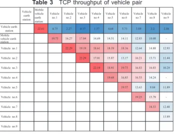
to a different channel, the fore STA and rear AP autono-mously connect to set up an ad-hoc network for multiple channels. With the assistance of the crisis management office, general affairs department, Hokkaido Prefecture, Hokkaido fire academy, the fire department headquarters of Ebetsu City, the fire department headquarters of Kita-Hiroshima City, and the fire department headquarters of the fire department affairs association of Iwamizawa dis-trict, we installed 10 network nodes on the fire vehicles and mobile vehicle earth station which can communicate through WINDS while in motion, and conducted basic empirical testing on the public roads in Ebetsu City, Hokkaido Prefecture. As the result, we could confirm that under vehicle stopping, 90 percent or more of the node pairs between vehicles had effective TCP throughput of 10 Mbps or more (Table 3). In addition, we confirmed that a high-definition image could be streamed to the internet through the network between traveling vehicles and the satellite. Figure 6 shows the mobile communication
ex-periment between vehicles using the fire vehicles and WINDS mobile vehicle earth station, and Fig. 7 shows the image streamed from the front vehicle to the internet through the network between vehicles and WINDS.
3.3 Speech quality evaluation of voice communication system using WINDS
We evaluated the sound quality for whether under-standing is possible when connecting to a telephone net-work using a WINDS line and the voice communication system.
3.3.1 Configuration of network for speech quality evaluation
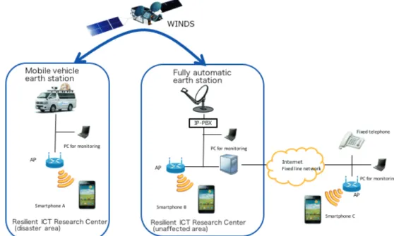
Figure 8 shows the network configuration built for the speech quality evaluation. The WINDS line is built by the 24 Mbps regenerative mode, and AP of Wi-Fi is placed on the mobile vehicle earth station. The order for the com-munication path to call a fixed telephone from smartphone A is as follows: Smartphone A ⇔ Wi-Fi on the mobile vehicle earth station ⇔ WINDS ⇔ fully automatic por-table earth station ⇔ IP-PBX ⇔ optical telephone GW ⇔ fixed line network ⇔ fixed telephone.
3.3.2 Conditions for speech quality evaluation
The speech quality evaluation methods include “subjec-tive sound quality evaluation methods” and “objec“subjec-tive sound quality evaluation methods.” The subject speech quality evaluation methods allow many estimators to correctly evaluate and directly evaluate the speech quality, but require much time and costs. On the other hand, the objective speech quality evaluation methods are often used because the entrenched objective sound quality evaluation methods which estimate the same value as the value obtained by the subjective sound quality evaluation method from physical characteristics of the sound can reduce the time and costs and have the advantage that the method always outputs the Vehicle earth station Mobile vehicle earth station Vehicle
no.1 Vehicleno.2 Vehicleno.3 Vehicleno.4 Vehicleno.5 Vehicleno.6 Vehicleno.7 Vehicleno.8 Vehicleno.9 Vehicle earth station 22.61 4.75 2.27 0.17 1.57 4.64 5.73 3.89 2.2 2.88 Mobile vehicle earth 19.73 16.27 17.84 14.69 14.51 14.11 12.83 10.08 -Vehicle no.1 22.29 19.19 18.61 18.19 18.16 12.64 14.88 12.93 Vehicle no.2 22.29 17.01 15.87 13.17 16.21 13.71 11.44 Vehicle no.3 22.19 18.91 19.73 16.83 16.03 10.29 Vehicle no.4 19.68 16.83 16.53 14.24 -Vehicle no.5 19.57 13.63 9.84 11.89 Vehicle no.6 19.25 15.79 -Vehicle no.7 18.53 12.48 Vehicle no.8 13.89 Vehicle no.9 station Table
T 3 TCP throughput of vehicle pair
Fig.
F 6 Appearance of mobile communication experience using fire
same evaluation value if the same input is given.
This study evaluated the speech quality using PESQ (ITU-T P.862), a media-layer model which is one of the objective speech quality evaluation methods.
The evaluation conditions are as follows: * Speakers
-Two men and two women -Fourteen speeches for each
-Total of six minutes (two seconds between speeches) -16 kHz sampling
* Connection
- Directly connect to the combo jack of a smartphone through a cable from an audio interface.
Figure 9 shows the devices used for sampling.
Moreover, the “speech database for research of the Acoustical Society of Japan” was used as speaker data.
3.3.3 Result of speech quality evaluation
We evaluated the speech quality using PESQ (ITU-T P.862) for whether understanding is possible when con-necting to telephone network using a WINDS line and the voice communication system. Figure 10 shows the results of the speech quality evaluation. The vertical axis is PESQ values, and the horizontal axis is types of telephone ap-plications. Here, we respectively evaluated the cases of using a “disaster phone,” using “Zoiper” which is a SIP client, calling a fixed telephone using “SkypeOut” from smartphone A and calling smartphone C using “LINE” from smartphone A, and we plotted the average values.
The PESQ values of the “disaster phone” were 2.6 with
the Speex8 k codec and 3.3 with the μ-law8 k codec, and the PESQ values of “Zoiper,” which is regarded as having good sound quality, were 2.7 with the Speex8 k codec and 3.1 with the μ-law8 k codec. Therefore, large differences are not shown from the results above.
In addition, the PESQ value of “SkypeOut” is 3.4, and the PESQ value of “LINE” is 4.0, the largest value. These are built by assuming primarily use under a high latency environment and the fluctuation of packets on the internet paths.
Although the evaluation methods are different, gener-ally, it is said that PESQ = 3.5 means that “90% of people” determine that “the said quality is better than usual (from the position of using phones routinely)”; PESQ = 3.1 means “80% of people” determine that “the said quality is better than usual (from the position of using phones routinely)”; and PESQ = 2.3 means that “40% of people” determine that “the said quality is better than usual (from the position of
Fig.
F 8 Network configuration of voice communication system
Fig.
using phones routinely)” [7]. In each case, it is found that the quality reaches a level where conversation is possible.
On the other hand, in Fig. 11 which shows the delay of voice, the “disaster phone” and “Zoiper” which use the fixed line network have delays from 400 to 500 msec., and for “SkypeOut,” a 715 msec. delay, the longest, arises. Therefore, it is considered that trouble arises in conversa-tion using phones.
4 Open experiment aimed at
municipalities, etc.
4.1 Open experiment to build an emergency communication network by the cooperation of WINDS and a small unmanned aircraft on “Sanuki medical rally” and to collect and convey information
The “Sanuki medical rally” is a place where medical personnel, firefighting officials, and the general public participate from Tohoku in the north to Kyushu in the south centering around Chugoku and Shikoku, to compete in points for disaster countermeasures in stages (simulated rescue and disaster site), and is also a place where opinions are exchanged on what to do concerning cooperation while
Fig.
F 10 Results of speech quality evaluation using PESQ (ITU-T P.862)
Fig.
deepening the level of understanding on disaster medical care. The first rally was held in June 2004, and continues today. Here, based on the “Sanuki medical rally” held in Sakaide City, Kagawa Prefecture, from May 24 to 25, 2014, we report on the open experiment in which we conducted empirical testing regarding the emergency communication network build-out using WINDS and a small unmanned airplane (UAS: Unmanned Aircraft System; hereinafter called UAS), and disaster information collection and com-munication.
The training assumes “the activity under the condition that many people are injured due to a train accident on the occurrence of a large-scale earthquake, and emergency medical teams and firefighters will be dispatched, but the public network cannot be used due to physical damage to the base transceiver station and congestion.”
For this reason, NICT first built the emergency com-munication network by linking UAS to mobile vehicle earth station which can perform satellite communications even in motion (Fig. 12). This allows the disaster countermea-sures office and rear areas to share information without congestion which has an effect on training participants (hereinafter “medical teams”). As it is required to view the disaster as a whole immediately after a request for support to medical teams, the images from the camera mounted on the UAS were sent to the disaster countermeasures office through the mobile vehicle earth station.
When medical teams and the fire department emer-gency relief teams move, while mobile vehicle earth station move together, the state of damages up to the disaster site, the available roads and their damage situations were sent in real time to the disaster countermeasures office by using
Fig.
F 12 Emergency communication network built by linking WINDS to a small unmanned aircraft (top), medical teams which check the site
the road damage collection system and the camera mounted on the mobile vehicle station. In addition, until the medical teams and the fire department emergency relief teams finished the activities from after arriving in the ac-tion areas, while providing an emergency communicaac-tion network to the medical teams, the site images were sent to the disaster countermeasures office from UAS and the mobile vehicle earth station.
The medical team acclaimed that the images from UAS before dispatching allowed them to prepare medical de-vices and medical goods.
4.2 Open experiment of the medical activity training at a large-scale earthquake in the Government’s comprehensive disaster preparation drill in 2016
The mobile vehicle earth station for WINDS, the mesh
network units, etc. are sent for the “2016 Medical activity training at a large-scale earthquake in the Government’s comprehensive disaster preparation drill” implemented on August 6, Saturday, and the training conducted an experi-ment in the “Emergency network support in case of a wide-scale disaster” using resilient ICT technology.
The drill assumed a Nankai trough earthquake, and was comprehensive actual work training regarding medical activities in the case of a wide-scale earthquake based on a plan, drawn up in March 2015, and so on, related to concrete emergency measure activities in case of a Nankai trough earthquake. In the 2016 case, in the Chubu block, the disaster medical assistance teams (DMAT) gathered to conduct the actual work training and map exercises for the wide-area medical transportation.
NICT placed a vehicle earth station for WINDS, mesh network units and ICT units in the Shizuoka prefectural
Fig.
F 13 Emergency network on the open experiment at the time of the medical activity training for a large-scale earthquake
Prefectural countermeasure office
Internet network by NICT (prefectural office) Internet network by NICT (Kosai) NTT satellite cell-phone Provided network services
WINDS Optical router
Inter net
NTTsatellite cell‐phone Vehicleearth stationforWINDS ICTunit
(MDRU)
Mobilevehicle earthstationfor WINDS
KashimaSpace TechnologyCenter
WINDSandICTunits(MDRU)providehigh‐ speedinternetnetworkandvoice
communicationswithWi‐FiatKosai base
Shizuoka prefecturaloffice
BaseontheKosai City
FieldhospitalinKosai City
WINDSandmeshnetwork nodesprovide high‐speed internetandvoice
communicationsinthe prefecturalcountermeasure headquarters Wi‐Fi
antenna
Fieldsituation(usingvoice communications,EMIS,etc.basedon cloud)
Mobilevehicleearthstation
forWINDSandMDRU Fieldetc.basedsituationoncloud)(usingvoicecommunications,EMIS,
Portable IP-PBX
Field hospital in Kosai City Mobile vehicle
earth station for WINDS and MDRU
ICT unit (MDRU) Vehicle earth station for WINDS
office (Shizuoka disaster medical headquarters) and an emergency network combining a mobile vehicle earth sta-tion for WINDS with ICT units (MDRU: NTT Network Innovation Laboratories) in the front base type SCU of Kosai City (field hospital), and provided the internet and call services to operate the wide-area disaster & emergency medical information system (EMIS), operated by DMAT in the case of a wide-scale disaster, and the intergovern-mental disaster prevention information sharing system of the National Research Institute for Earth Science and Disaster Prevention, or to communicate between disaster sites and the disaster countermeasures office (Fig. 13).
After finishing the drill, the concerned parties of DMAT acclaimed the availability of NICT’s resilient ICT technol-ogy in terms of ensuring data communications of the satel-lite system, because in the mobile telephone network and the internet network, congestion as well as physical dam-ages due to earthquake motion would certainly arise.
We need to further improve the performance including the operation side while announcing the availability of resilient ICT technology resistant to disaster by making public the NICT research and development results through cooperation with DMAT and local governments.
4.3 Open experiment on the 2016 comprehensive disaster preparation drill of Ehime Prefecture
We sent vehicle earth stations for WINDS to the “2016 comprehensive disaster preparation drill of Ehime Prefecture” implemented at the Uwa athletic park in Seiyo City, Ehime Prefecture, on August 28, Sunday, 2016, and conducted the open experiment for building the emer-gency communication network and the disaster informa-tion transfer using WINDS.
The drill, assuming a complex disaster due to an earth-quake and a sediment disaster, was practical training fo-cused on the cooperation of disaster prevention agencies and private cooperative bodies. NICT relayed the rescue operation situations in real time from three places: the Uwa athletic park, the site countermeasure headquarters; the transport site for disaster relief materials; and the Seiyo civilian hospital, a disaster core hospital, to YouTube using WINDS, while providing lines for the “Disaster informa-tion system of Ehime Prefecture (cloud)” (Fig. 14).
We received affirmation from prefectural agencies that the operation of the “Disaster information system of Ehime Prefecture (cloud)” through the communication satellite was possible. In addition, the high-speed internet in the local countermeasure headquarters was assessed to be the last measure if no alternative means exist.
Fig.
F 14 Image of disaster information transfer
M o b ile v ehicle ea rth sta tio n
Ta b le t PC for d isa ste r in form a tion sy ste m
In te r n e t O n-site co unterm ea sure hea d q uarters
M o n ito r (fo r o n -site c o u n te rm e a su re h e a d q u a rte rs)
TV c a m e ra
Initia l resp o nse a ctiv ities
Tra n sp ort site f or d isa ste r re lie f m a te ria ls
Pre fe c tu ra l d isa ste r c o u n te rm e a su re h e a d q u a rte rs: a c c e ss to th e d isa ste r in fo rm a tio n syste m u sin g a PC, e tc .
A u th o ritie s c o n c e rn e d : a c c e ss to th e d isa ste r in fo rm a tio n syste m u sin g a sm a rtp h o n e , ta b le t, e tc .
W i-Fi
W IN D S
Re a l-tim e re la y of d isa ste r d rill situ a tion
D isa ste r in f orm a tion sy ste m of Eh im e Pre fe c tu re (c lou d )
D isa ste r c o re h osp ita l
K a sh im a Sp a c e Te c h n olog y C e n te r
Ve h ic le e a rth sta tion for W IN D S
5 Building the 2016 Kumamoto Earthquake
emergency network using WINDS
After the foreshock occurred at 21:21 on April 12, 2016, and the main shock occurred at 1:25 on April 16, 2016, earthquakes occurred in Kumamoto and Oita Prefectures one after another. 49 people in Kumamoto Prefecture died in crushed houses and by being involved in a sediment disaster by this series of earthquakes. Furthermore, almost 100 thousand cases of house damage arose with a focus on Kumamoto Prefecture [8].
In addition, these earthquakes caused damage to a maximum 2,100 fixed lines, and suspended the radios of a maximum 350 stations due to battery depletion by broken transmission paths and blackouts [9].
On the other hand, after the 2011 Great East Japan Earthquake, to realize a wireless network system resilient to disasters, NICT has carried out research and development regarding wireless systems, such as satellite communications and unmanned aircraft system, and wireless networking technology where wireless terminals dispersedly arranged over a wide range autonomously operate in a coordinated way, and to enable more rapid emergency network-building when communication cuts occur extensively.
In response to the Kumamoto Earthquakes, NICT sent materials and equipment, such as the mesh network and the vehicle earth stations for WINDS, which enable
ultra-high-speed satellite communications, and dispatched re-searchers to Takamori Town, Kumamoto Prefecture, to build the emergency network and implement the operation.
5.1 Reason, purpose, and movement of dispatch
The Ministry of Internal Affairs and Communications sounded the NTT Network Innovation Laboratories to form a usage environment for the emergency network in disaster areas. NICT considered it as an important ap-proach for the demonstration of ICT restoration techniques at disaster areas for the activities of the resilient ICT center and for the demonstration of disaster-resistant technology by SIP. Therefore, NICT jointly implemented it with the NTT Network Innovation Laboratories under the SIP framework.
The contents of the emergency network-building were to build temporary lines until network recovery, to build phone lines by IP-PBX (NTT Network Innovation Laboratories), to provide internet connection service with the mesh network and to operate WINDS as backhaul.
The dispatch was determined at around 19:00 on April 16 on which the main earthquake occurred, and the dis-patched personnel gathered by 12:00 on April 17. After preparing materials and equipment, at around 13:00 in the day, they departed the resilient ICT research center in Sendai.
Although the initial planned dispatch site was Ube City whose municipal office was damaged due to earthquake
Fig.
F 15 Emergency network configuration using WINDS
WINDS
Town office of Takamori Kashima Space Technology Center
MBA kantobeam
L2VPN
51MV SAT
large-scale in-vehicle earth station
Optical line Gate Way Internet
Telephone network
MBA Kyushu beam
Router L2VPN
L2VPN L2VPN
AP for government (13:30) AP for residents (14:30)
motion, the dispatch destination was changed to the town office in Takamori Town during traveling.
Because we used the vehicle earth stations for WINDS to move, we took the route to the dispatch destination through Tohoku, Ban-etsu, Hokuriku, San-in, Mei-shin, Sanyo and Kyushu expresses, ran the northern route around Mt. Asosan, and arrived at the town office in Takamori Town at around 20:00 on April 18. Moreover, the total travel distance was about 1,600 km which took 30 hours.
5.2 Emergency network building using WINDS, and usage conditions of the network
After adjusting with the staff of the disaster counter-measures office of Takamori Town, we decided to build the emergency network using WINDS on April 19. We built the WINDS lines using 51 Mbps mode at around 9:00 on April 19. Then, we prepared one AP of the mesh network for the government, and provided the network to the di-saster countermeasures office (General Affairs Division) at around 13:30. We decided to set a password on this network and not to release the network to residents for personal information protection, etc. In addition, we placed the mesh network AP having the same configuration near the entrance of the town office at around 14:30. We decided that this AP was for residents and not to set a password so that everyone could use it. Figures 15 and 16 respectively show the block diagram for the emergency network using WINDS, and the mesh network AP placed in the disaster countermeasures office (General Affairs Division).
For future research and development, we measured how much the networks were used for the AP for government and the AP for residents. For AP for government, the maximum throughput scored 18 Mbps two or three hours
after placement. It is believed that after placing the emer-gency network, the staff implemented information collec-tion that could not have been done otherwise, and after finishing the collection it was not necessary to use the internet for a while. Figure 17 shows the AP throughput for government and Fig. 18 shows the situation of the di-saster countermeasures office.
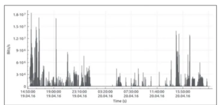
For AP for residents, the maximum throughput scored 18 Mbps at around 8:00 in the evening. We think that this is because the evacuees who came back to their houses in daytime returned to the evacuation center to use SNS and collect information on the internet while charging their smartphones, etc.
In addition, one characteristic of how to use the net-work for residents is that the throughput tends to rise in time slots for meals of breakfast, lunch and supper. Figure 19 shows the throughput of AP for residents, and Fig. 20 shows the usage situation of the network for resi-dents.
6 Summary
We introduced the research and development, advanced by NICT, and the main content of the empirical testing
Fig.
F 17 Throughput of AP for government
Fig.
F 18 Situation of the disaster countermeasures office
Fig.
F 16 Emergency network AP which was set up in the disaster
aiming for satellite communications available for disaster countermeasures. In addition, we also shortly introduced the usage content when being dispatched to Takamori Town, Kumamoto Prefecture at the time of the 2016 Kumamoto Earthquakes. As observed in the Great East Japan Earthquake that occurred in 2011 and the 2016 Kumamoto Earthquakes, wide-scale disasters almost in-variably cause communication failures.
Based on these, in the future, we would like to advance the research and development of the satellite communica-tion network so that the emergency network can be built promptly.
ReReRenRe R
1 NRIFD: Report of the Damage and Firefighting activities of the 2011 Tohoku Earthquake and tsunami (1st report, in Japanese), no.82, 2011
2 T. Takahashi etc. all: Disaster Satellite Communication Experiments using WINDS and Wireless Mesh Network, GWS 2013, 2013.
3 Catch the disaster damage information using car navigation information; Detection of impassable road, Ministry of Land, Infrastructure and Transport (in Japanese), Retrieved June 30, 2017., https://news.yahoo.co.jp/pickup/6086738 4 NRIFD: Report of the Damage and Firefighting activities of the 2007 Noto
Peninsula earthquake and Tohoku Earthquake and tsunami (in Japanese), no.82, 2011
5 K. Yagi: Improvement of the Road Bump detection method by using
smart-phone and an application result of Tohoku earthquake (in Japanese), Proceeding of Traffic Engineering of Japan, no.31, pp.249–252, Aug.2011
6 T.Clausen, et al., “The Optimized Link State Routing Protocol Version 2,” IETF RFC7181, April 2014.
7 K. Asatani: Quality design of the communication network (in Japanese), IEICE, 1993
8 Fire and Disaster Management Agency of Japan: Prompt Report of the 2016 Kumamoto Earthquake (no.48, in Japanese), Retrieved June 30, 2017., http:// www.fdma.go.jp/
9 Disaster Countermeasure Headquarter of MIC: Prompt Report of damage of the 2016 Kumamoto Earthquake (no.35, in Japanese), Dead link
Byong-pyo JEONG, Dr. Eng. Senior Researcher, Applications Laboratory, Resilient ICT Research Center
Disaster response, GIS Satellite communication
Hajime SUSUKITA
Planning and Collaboration Promotion Office, Resilient ICT Research Center
Satellite communication
Tomoshige KAN, Dr. Eng. Researcher, Space Communications Laboratory, Wireless Networks Research Center
Satellite communication propagation
Toshio ASAI
Space Communications Laboratory, Wireless Networks Research Center
Satellite communications system
Akira AKAISHI
Space Communications Laboratory, Wireless Networks Research Center
Satellite communications system
Fig.
F 19 Throughput of AP for residents
Fig.
Kazuyoshi KAWASAKI
Senior Researcher, Space Communications Laboratory, Wireless Networks Research Center
Satellite communication
Takashi TAKAHASHI
Associate Director, Space Communications Laboratory, Wireless Networks Research Center