Submitted to the Graduate School of Systems and Information Engineering in Partial Fulfillment of the Requirements
for the Degree of Master of Engineering at the
University of Tsukuba
Gesture for Large Display
- Comparing Sensor Based and Vision Based Techniques for Dynamic Gesture Recognition -
March 2012
Bayasgalan Baatar
( Master’s Program in Computer Science )
Advised by Jiro Tanaka
Abstract Abstract Abstract Abstract
Hand gesture recognition is of great importance for human computer interaction (HCI), because of its extensive applications in large display interaction. The traditional interaction methods are not so suitable for large display interaction and demand for natural interaction methods. We focus on one of the natural interaction methods, the hand gesture in our research, which is most expressive, natural, and intuitive because hand is the most frequently used manipulation tool for human and most suitable for large display control.
There are mainly two types of hand gesture recognition techniques: vision based and sensor based techniques. Each technique has its own merits and restrictions and to decide which technique to use in our gesture application is difficult. Our research purpose is to evaluate these two techniques to find out which technique is better for which kind of gesture interaction.
In our work, first, we classified hand gesture based on task analysis. We restricted our work to dynamic gesture recognition and we implemented a Google Earth Hand Gesture Navigation System for dynamic gesture recognition evaluation purpose.
We conclude the paper with an evaluation of both techniques and describe user tests, which were conducted to study user`s habit to perform gesture and user`s preference for each technique.
Contents
Chapter 1 Introduction ··· 1
1.1 Background ··· 1
1.1.1 Large Display··· 1
1.1.2 Large Display Interaction ··· 2
1.1.3 Basic Tasks for HCI ··· 4
1.1.4 Gesture ··· 4
1.2 Gesture Recognition ··· 7
1.3 Purpose and approach ··· 9
1.4 Organization ··· 10
Chapter 2 Related works ··· 11
2.1 Accelerometer based gesture recognition ··· 11
2.2 Bare hand tracking ··· 12
Chapter 3 Our Gesture Classification ··· 13
3.1 Classification ··· 13
3.2 Relation between our gesture classification and basic HCI tasks ··· 14
Chapter 4 Gesture Recognition Techniques for Each Gesture ··· 15
4.1 Static Gesture Recognition ··· 15
4.2 Dynamic Gesture Recognition ··· 17
4.3 Dynamic Gesture with Posture Recognition ··· 18
4.4 Object Gesture Recognition ··· 18
Chapter 5 Google Earth Hand Gesture Navigation System ··· 19
5.1 System Overview ··· 20
5.2 System Architecture ··· 21
5.2.1 Hardware ··· 21
5.2.2 Software ··· 22
5.3 Gesture Recognizer module ··· 23
5.3.1 Sensor Based Interface ··· 23
5.3.2 Vision Based Interface (Static) ··· 24
5.3.3 Vision Based Interface (Dynamic) ··· 26
5.4 Google Earth Navigator module ··· 29
Chapter 6 Evaluation ··· 30
6.1 User evaluation ··· 30
6.1.1 Experiment 1 ··· 30
6.1.2 Results for experiment 1 ··· 30
6.1.3 Experiment 2 ··· 33
6.1.4 Results for experiment 2 ··· 33
6.2 Analysis ··· 37
Chapter 7 Conclusion and Future Work ··· 39
Acknowledgements ··· 40
List of Figures
1.1 Large Display Interaction Levels [4] ... 3 1.2 Kendon`s gesture continuum [13] ... 6 3.1 Relation between our gesture classification and basic HCI tasks: (a) static gesture for selection task, (b) dynamic gesture with posture for manipulation task, (c) dynamic gesture for navigation task, (c) static gesture for symbolic input task ... 14 5.1 Google Earth Hand Gesture Navigation System ... 20 5.2 Google Earth Hand Gesture Navigation System hardware component: (a) sensor based interface, (b) vision based dynamic interface, (c) vision bases static interface ... 22 5.3 Accelerometer Signal processing and gesture recognition process ... 23 5.4 Dynamic Time Warping (DTW) algorithm ... 24 5.5 Motion gesture time line [18] a) frame t, no motion detected. b) frame t + 1, motion orientation detected, the clock and arrow indicate the motion orientation is right. c) frame t + 2, motion orientation is right. d) frame t + 3, motion orientation is r ... 25 5.6 Open Hand ... 26 5.7 Hand detection: (a) skin color segmentation, (b) convex hull based hand shape representation ... 27 5.8 Optical Flow hand tracking: (a) not moving hand, (b) hand moving to left ... 28 5.9 Recognizing Gesture ... 28 5.10 Latitude and Longitude of Earth: (a) North ↔ South navigation, (b) Left
↔Right navigation ... 29
List of Tables
4.1 Recognition techniques for our gesture classification ... 15
5.1 Dynamic gesture and corresponding Google Earth actions ... 21
5.2 Non-linear quantization ... 24
5.3 BRG skin color space ... 26
5.4 Google Earth Actions corresponds to each gesture ... 29
6.1 Vision based (static) interface accuracy ... 31
6.2 Vision based (dynamic) interface accuracy ... 31
6.3 User comments for static interface ... 32
6.4 User comments for dynamic interface ... 32
6.5 Sensor interface accuracy ... 34
6.6 Vision based (dynamic) interface accuracy ... 34
6.7 Average duration and step for navigating from Africa to Japan ... 34
6.8 User comments for static interface ... 35
6.9 User comments for static interface ... 36
Chapter 1
Introduction
1.1 Background
1.1.1 Large Display
Large scale public displays are increasingly found at train stations, airports, bus stops, or in shopping malls. The rapid advancement of display technology makes ever larger high-resolution displays increasingly available and affordable. Large displays give an excitement to users because large displays allow us to view and interact with data and collaborators in ways that were not possible with standard-sized displays. These kinds of displays offer great opportunity for information visualization and manipulation which helps much to improve performance for complex, multi-application work and rich information tasks and group work. It also enhances users’ awareness of peripheral applications, and offer immersive working experiences.
Following is the possible application areas on large high-resolution display [1]
Command and Control: Large high-resolution displays have been widely installed in command and control centers for a variety of applications including military, aerospace, and telecommunications. The Air Force Research Laboratory developed the Interactive Data Wall for situational awareness and collaborative decision making tasks involving battlefield data.
Vehicle design: It has been a fundamental requirement of the automotive design industry to display and interact with vehicle models at 1:1 scale.
Therefore, automotive design studios have explored the use of a variety of large-format digital displays applications to evaluate human factors and ergonomics, analyze complex engineering data, and build capabilities in vehicle manufacturing process development
Geospatial imagery and video: Large high-resolution displays offer the sense of scale needed for geospatial imaging and large film-quality video applications. High-resolution display systems are used by several major oil and gas companies for geospatial exploration and engineering, 3D mapping,
and geophysical analysis
Information visualization: Large high-resolution displays have been one of the favorite choices for scientific visualization applications because they offer viewing of data at true-to-life or human-scale physical sizes and viewing of large amounts of data simultaneously with the increased number of pixels available.
Collaboration: An integral part of collaborative work is a public display surface that serves as a medium for presenting, capturing, and exchanging ideas. A large high-resolution display is an ideal facility for tele-immersion applications, since collaborative exploration of massive scientific data sets requires a large screen real estate.
Education and training: Large high-resolution displays are a great tool for education and training in astronomy, bioinformatics, medical imaging, urban planning, and geographic information. UC-Santa Cruz has developed a collaborative learning environment for the classroom by using a large shared tile-wall display. The display space is shared by the instructor and students.
The large display space provides the primary means of presentation of lecture material, allowing the lecturer to keep multiple screens of material in view for the students.
Immersive applications: large displays can be used to create Virtual immersive environment which can be used such as users to practice fire safety procedures inside of buildings, ships, and other environments.
Digital signage: a form of electronic display that shows television programming, menus, information, advertising and other messages. Digital signs can be found in public and private environments, such as retail stores, hotels, restaurants and corporate buildings.
1.1.2 Large Display Interaction
There are two kinds of interaction methods; traditional and natural [2].
Traditional interaction methods include more artificial control devices such as;
mouse, keyboard and pen, etc., whose operation has to be learned by users. In a contrast, the natural interaction methods allow user to control the computer system more natural way. This method includes gesture, body language, touch, and voice, etc. The traditional interaction method is not so suitable for large display interaction and demand for interaction method using natural methods. We
will concentrate on one of the natural interaction methods, the gesture, in our research because gesture interaction is most suitable interaction method for large display control while large displays require more physical navigation and are not always reachable to touch. Nor speech input is desirable in noisy environment such as shopping mall.
We can divide large display gesture interaction into four levels [4] (Figure1.1).
Level1 is the most basic 2D interaction level. In this level user interacts with 2D objects by performing gesture in 2D space. In level2 user interacts with 3D objects inside screen by performing gesture in 3D space. In level3 user interacts with 2D or 3D virtual objects inside screen with help of real objects inside room. For instance, when user makes throwing gesture to real garbage bin inside the room, the virtual objects inside the screen will be removed. This is a one kind of Mixed Reality interaction [3], using everyday objects around us as a command input. In level4 the user`s view is not restricted to inside the screen. User can see the virtual and real objects everywhere with help of projection display or HMDs. For instance, surgeons use 3D visualization on patient’s body during the medical operation [5].
Figure Figure Figure
Figure 111....11111 Large Display Interaction LevelsLarge Display Interaction LevelsLarge Display Interaction Levels [4]Large Display Interaction Levels[4][4][4]
1.1.3 Basic Tasks for HCI
In HCI, basically, the computer performs a task and responds to user command.
Therefore, understanding what kinds of tasks exist is important to know what kinds of gestures are needed to interact with computer. Therefore, we tried to carefully look at a basic task analysis before classifying gestures. The most basic tasks [6] for human computer interaction include selection, manipulation, navigation and symbolic input. Complex tasks often are built up of these basic task components.
Selection task is a specification of one (single selection) or more objects (multi selection) from a set; as the object of a command or to begin manipulation. In case of traditional interaction method, the single selection task is made by mouse single click operation and multi selection is done by mouse single click and drag.
Manipulation task is specification of the position, orientation, and/or scale of an object. Manipulation tasks involve selecting and moving an object. Sometimes, rotation of the object is involved as well. Examples of manipulation task are resizing pictures, editing files content and location using traditional mouse and keyboard devices.
Navigation task is movement between 2 locations, setting the position (and orientation) of the user’s viewpoint. The computer needs to provide the user with information regarding location and movement.
Symbolic input task is an input of numerical/symbol data. Symbolic input techniques include: keyboard, pen, gesture and speech.
1.1.4 Gesture
1.1.4.1 About Gesture
Gestures are expressive, meaningful body motions, physical movements of the fingers, hands, arms, head, face, or body with the intent to convey information or interact with the environment. In the HCI literature the word gesture has been used to identify many types of hand movements for control of computer process.
However, getting one's hand to the place to start creation or manipulation is not considered a gesture, because it is a necessity to move your hand, but it does not contribute to the final product as such. The way you move your hand to reach this point is not important [7]
According to McNeill [8] the dynamic gesture movement consists of three parts Approach: body begins to move
Stroke: the gesture itself
Return: return to balanced posture
Gesture is widely divided into static and dynamic. But some gestures have both static and dynamic elements, where the pose is important in one or more of the gesture phases.
1.1.4.2 Gesture Interface Design
Gesture interface design has two types: not pre-defined (perceptual) and pre-defined [9]. Current research on gestures focuses on pre-defined interface while perceptual interface design is complicated and difficult.
Not pre-defined natural gesture interaction
Perceptive user interface (PUI) aims to recognize natural human gestures which may accompanied with other human expressions, such as facial expression and body movements. This kind of interface also dedicates to fulfill the human computer interaction as natural as human-human dialog. This need the interface to be able to pick up intended gesture commands from a serial of movements which may include lots of unintended gestures. Even to pick up some unintended gestures which may also contain some useful information for some intelligent adjust, such as automatic volume down the music when user picking up a phone.
Pre-defined gesture interaction
Pre-defined user interfaces, where hand poses and specific gestures are used as commands in a command language. The gestures are not necessary to be natural but could be developed for the situation, or based on a standard sign language. The gesture commands in this case are only tends to take place some other HCI devices in some special situations, such as turning to next slide remotely without holding a mouse during a representation. Even the PUI with passive input mode sound much more novel and florid, pre-defined user interface is much easier to be implemented and much more reliable and error-proof.
Pavlovic [10] noted that, ideally, naturalness of the interface requires that any and every gesture performed by the user should be interpretable, but that the state of the art in vision-based gesture recognition is far from providing a satisfactory solution to this problem. A major reason obviously is the complexity associated with the analysis and recognition of gestures.
However, in this paper the focus is on using hand gestures given purposefully as instructions, and we restrict our work to dynamic gesture recognition. This falls within the second approach to gestural interfaces, pre-defined gesture interaction, where hand poses and specific gestures are used as commands in a command language.
1.1.4.3 Current Gesture Classifications
Currently, the gestures are classified in various ways.From the anatomical point of view, the gestures can be classified into: hand and arm gesture, head and face gesture and body gesture [11]. We are concentrating on hand and arm gesture in our research because it is most expressive, natural, intuitive and most frequently used and most suitable for large display interaction. Hand movements can be classified as followings, according to their functionality [12]: semiotic, ergotic, and epistemic. Semiotic means to communicate meaningful information and results from shared cultural experience. Ergotic is associated with the notion of work and the capacity of humans to manipulate the physical world, create artifacts.
Epistemic allows humans to learn from the environment through tactile experience or haptic exploration.
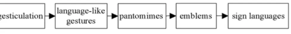
Kendon`s gesture continuum [13] (Figure 1.2) emphasizes the strong connection between speech and gesture.
Figure Figure Figure
Figure 111....21222 Kendon`s gesture continuum [1Kendon`s gesture continuum [1Kendon`s gesture continuum [13Kendon`s gesture continuum [133]]]] 3
While going from gesticulation to sign languages the formalized, linguistic component of the expression present in speech is replaced by signs going from gesticulation to sign languages:
Gesticulations are spontaneous movements of the hands and arms during speech.
Gesticulation almost never occurs in the absence of speech. For example, point finger up gesture while saying “go up!”. Language-like gestures is a gesture replacing particular spoken word or phrase. In this case, the speech stops in order to perform gesture. For example, person says “It was right here yesterday, but [gesture]”, where doing shoulder shrugging gesture by conveying a meaning “who knows? I have no idea”. Pantomimes are a sequence of a gesture that has narrative
function, used in theaters for storytelling. Emblems are specific hand postures which has a fixed form of meaning. But meaning may vary across different cultures. Sign-languages are well defined linguistic communication system
Hence, decoding information from gesture is not important for pre-defined user interface, we can classify gesture as a static (hand posture) and dynamic (hand movement) based on the technical point of view. Hand posture and hand movements are both defined as the motion of fingers, hands and arms. Hand posture is defined as the position of the hand and fingers at one instant in time.
However, hand posture and gesture describe situations where hands are used as a means to generally use to indicate use of the hands for communication purposed without physical manipulation of any object
1.2 Gesture Recognition
Vision based hand gesture recognition is believed to be an effective technique and number of system have been proposed. There are following types of vision based technique: marker based, skin color detection, and motion detection techniques. A static gesture is a particular hand configuration and pose, represented by a single image. A dynamic gesture is a moving gesture, represented by a sequence of images. Picking up the most important features with controlling information from variant and complex hands movements is the key technic for gesture recognition system. A static hand postures can act as a special turning state of a dynamic gesture, and also a dynamic gestures can be captured and analyzed as a set of static gestures. Recognizing and extracting temporal gestures from movements are handled by the finite state machine technique with serial movements with start signals as inputs.
The environment noise is an encumbrance for gesture recognition based on computer vision, due the gesture modeling and training work normally has been done in optimal environment. A noisy background with similar color as human skin (same as human eyes hardly to find out an anole even it is just front of you), or a working environment with lots of moving objects in the observing area will dramatically impede the performance of the recognizing system, and enhance the error rate.
Human body language is abundant and able to convey lots kind of expressive information. However, in the vision based human computer gesture interaction scenarios, not all of gestures intend to express controlling intentions, even gestures which have already been defined as gesture control commands can also
convey some non-control expressions in some kind of situations. Ignoring un-intended gestures for gesture commands controlling systems is important for error control, also can prevent the system from dealing with useless information, and reduce the workload of the system.
Vision-based techniques vary among themselves in 1) the number of cameras used, 2) their speed and latency,3) the structure of environment such as lighting and speed of movement, 4) any user requirements such as any restrictions on clothing, 5) the low-level features used such as edges, regions, silhouettes, moments, histograms, and others, and 6) whether 2D or 3D is used. Therefore, these limitations restrict the applications of vision-based systems in smart environments. More specifically, suppose you are enjoying watching movies in your home theatre with all the lights off. If you decide to change the volume of the TV with a gesture, it turns out to be rather difficult to recognize your gesture under poor lighting conditions using a vision-based system. Furthermore, it would be extremely uncomfortable and unnatural if you have to be directly facing the camera to complete a gesture [11].
A very promising alternative is to resort to other sensing techniques such as acceleration based techniques or electromyogram-based (EMG-based) techniques.
Acceleration-based gesture control is well-suited to distinguish noticeable, larger scale gestures with different hand trajectories. However, it is not very effective when it comes to detecting more subtle finger. Gesture recognition based on data from an accelerometer is an emerging technique for gesture-based interaction after the rapid development of the MEMS technology. Accelerometers are embedded in most of the new generation personal electronic devices such as Apple iPhone, Nintendo Wiimote which provide new possibilities for interaction in a wide range of applications, such as home appliances, in offices, and in video games [11].
Recognition of natural, continuous gestures requires temporally segmenting gestures. Automatically segmenting gestures difficult, and often finessed or ignored in current systems by requiring a starting position in time and/or space.
Similar to this: problem of distinguishing intentional gestures from other
“random” movements. No standard way to do gesture recognition, variety of representations and classification schemes used. However, most gesture recognition systems share some common structure.
1.3 Purpose and approach
Hand gesture recognition is of great importance for human computer interaction (HCI), because of its extensive applications in large display interaction. There are mainly two types of hand gesture recognition techniques: vision based and sensor based techniques. Vision-based systems contain rich visual information which is a strong cue to infer the inner states of an object and this technique can track and recognize the hand even when it is not touching the surface or not wearing a device. At the same time, vision-based systems can be very cost efficient and noninvasive, making vision systems very feasible. However, it has some limitations of the optical sensors, the quality of the captured images is sensitive to lighting conditions and cluttered backgrounds, thus it is usually not able to detect and track the hands robustly, which largely affects the performance.
Sensor based technique is another basic alternative to hand gesture recognition which is usually more reliable and are not affected by lighting conditions or cluttered backgrounds. However, as it requires the user to wear a data glove and sometimes requires calibration, it is inconvenient for the user and may hinder the naturalness of hand gesture.
Apparently, each technique has its own merits and restrictions and to decide which technique to use in our gesture application is difficult. Our research purpose is to compare these two techniques to find out which technique is better for which kind of gesture interaction
For that, first, we classified gesture based on technology driven aspect and proper task analysis. Because, most current gesture classifications are based on human behavior but it’s not so useful for most current applications which are technology driven and command task input. We implemented a Google Earth Hand Gesture Navigation System for evaluation for dynamic gesture recognition purpose. Then, we conducted a user study and made an evaluation for both techniques.
1.4 Organization
This thesis is organized as follows. In Chapter 2 we present the related works. In Chapter 3 we outline the details about our gesture classification. In Chapter 4 we introduce the relation between our gesture classification and gesture recognition techniques. In Chapter 5 we introduce our system, Google Earth Hand Gesture Navigation and its details, which are used for gesture recognition techniques comparison for dynamic gesture detection. In Chapter 6 we discussed evaluation and result. Finally, Chapter 7 presents the conclusions and future works.
Chapter 2
Related works
In this chapter, we present some related works to accelerometer based gesture recognition and bare hand tracking.
2.1 Accelerometer based gesture recognition
Ahmad Akl[11] presented a novel gesture recognition system based solely on data from a single 3-axis accelerometer. The system employs dynamic time warping and affinity propagation algorithms for efficient training. The author proposed user-dependent, missed-user and user-independent recognition and compared it to other similar gesture recognition systems such as uWave [15].
uWave is a user-dependent system that supports personalized gesture recognition.
Liu et al. developed uWave system on the premise that human gestures can be characterized by the time series of the forces measured by a handheld device. The input to uWave is a time series of acceleration provided by a 3-axis accelerometer.
uWave starts by quantizing the acceleration values into discrete values.
Quantization of Library templates is also done. The quantized input time series is then compared to the library templates by dynamic time warping (DTW) and then the time series are recognized as the gesture whose template yields the lowest cost.
The core of the uWave is DTW since it is very effective in coping with limited training data and small vocabulary gestures. However, for a larger vocabulary, HMM-based methods are the chosen techniques since they are more scalable and can create better models from a large set of training data.
2.2 Bare hand tracking
Barehanded means that no device and no wires are attached to the user, who controls the computer directly with the movements of his/her hand.
In the last ten years, there has been a lot of research on vision based hand gesture recognition and finger tracking. Interestingly there are many different approaches to this problem with no single dominating method. The basic techniques include color segmentation [26], infrared segmentation [17], blob-models [26], and contours [16]. Typical sample applications are bare-hand game control, and bare-hand television control [25]. Most authors use some kind of restriction, to simplify the computer vision process:
Non real-time calculations Colored gloves [27]
Expensive hardware requirements (e.g. 3D-camera or infrared camera) [17]
Restrictive background conditions
Explicit setup stage before starting the tracking
Restrictions on the maximum speed of hand movements
Most systems additionally have problems in the case of changing light conditions and background clutter. None of the presented work provides a robust tracking technique for rapid hand movements. In addition, most systems require some kind of setup-stage before the interaction can start.
Hand Gesture for Taking Self Portrait [18] proposed a new approach for hand motion tracking which is able to detect fast motion.
Chapter 3
Our Gesture Classification
3.1 Classification
Based on our survey result, we classified hand gesture in to four categories: static, dynamic, dynamic gesture with posture, and object gesture.
S S S
Static gesturetatic gesturetatic gesturetatic gesture is same as Kendon’s emblem gesture [13] and it consists of only hand postures. Static gesture has a qualitative nature because it cannot be measured by any number and can only be observed by its appearance and shape.
Therefore, static gesture can convey only a specific meaning.
Dynamic gesture Dynamic gesture Dynamic gesture
Dynamic gesture consists of only hand motions. In contrast to static gesture, dynamic gesture has a quantitative nature because it can be measured in volume, length, or speed. We cannot observe it by its appearance. Therefore, dynamic gesture can convey only a meaning of motion and direction.
Dynamic gesture with posture Dynamic gesture with posture Dynamic gesture with posture
Dynamic gesture with posture is a more high level gesture having both static and dynamic elements. In this gesture, a posture acts as a specific transition in during the motion.
Object gesture Object gesture Object gesture
Object gesture is a gesture holding or interacting with object in the environment.
This is a one variation of Dynamic gesture with posture where posture is an object because objects also have a qualitative nature, same as a static gesture. We can observe it by its shape, color and other attributes. Object gesture is very important for the gesture interaction in mixed reality.
3.2 Relation between our gesture classification and basic HCI tasks
Here, we present the relation between our gestures classification and basic HCI tasks [6]. Single selection is a task which specifies single element from a set.
Therefore, a gesture which has a corresponding qualitative meaning is needed to perform this task. This gesture is a static gesture. For example static gestures such as pointing or grasping postures are commonly used for selection tasks (Figure 3.1 (a)).
Multiple selection and manipulation task are usually answers to the question of
“what and how much?” which means it has both of qualitative and quantitative elements. Therefore, Dynamic gesture with posture will be executed to perform this task (Figure 3.1 (b)).
Navigation task is movement between 2 locations, setting the position (and orientation) of the user’s viewpoint. Therefore, it answers to the question of “how long, how much?” which means it’s all about quantitative things. Therefore, dynamic gesture, which requires only motion to various directions, corresponds to this task (Figure 3.1 (c)).
Symbol is all about quantitative thing. Therefore, symbolic input task is executed by static gesture (Figure 3.1 (d)).
(a) (c)
(b) (d)
Figure Figure Figure
Figure 333....13111 RelatRelatRelatRelation between our gesture classification and basic HCI tasksion between our gesture classification and basic HCI tasksion between our gesture classification and basic HCI tasksion between our gesture classification and basic HCI tasks: (a) static : (a) static : (a) static : (a) static gesture for selection task, (b) dynamic gesture with posture for manipulation task, (c) gesture for selection task, (b) dynamic gesture with posture for manipulation task, (c) gesture for selection task, (b) dynamic gesture with posture for manipulation task, (c) gesture for selection task, (b) dynamic gesture with posture for manipulation task, (c) dynamic gesture for navigation task, (c) static gesture for symbolic input task
dynamic gesture for navigation task, (c) static gesture for symbolic input task dynamic gesture for navigation task, (c) static gesture for symbolic input task dynamic gesture for navigation task, (c) static gesture for symbolic input task
Chapter 4
Gesture Recognition Techniques for Each Gesture
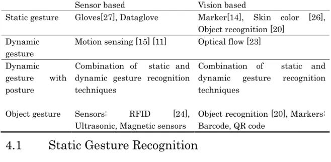
In this chapter, we will explain the relation between our gesture classification and gesture recognition techniques of the sensor based and vision based techniques (Table 4.1). Kinect is a recent development of inexpensive depth cameras, e.g., the Kinect sensor. This is new opportunities for hand gesture recognition emerges and we consider is as a combination of both sensor and vision based technique. But we do not look at Kinect in our research; instead we concentrate on very basic two techniques and their comparison.
Table Table Table
Table 4444....1111 RRRReeeecognition techniques for our gesture classificationcognition techniques for our gesture classificationcognition techniques for our gesture classificationcognition techniques for our gesture classification
Sensor based Vision based
Static gesture Gloves[27], Dataglove Marker[14], Skin color [26], Object recognition [20]
Dynamic gesture
Motion sensing [15] [11] Optical flow [23]
Dynamic
gesture with posture
Combination of static and dynamic gesture recognition techniques
Combination of static and dynamic gesture recognition techniques
Object gesture Sensors: RFID [24], Ultrasonic, Magnetic sensors
Object recognition [20], Markers:
Barcode, QR code
4.1 Static Gesture Recognition
Sensor based Technique Sensor based Technique Sensor based Technique Sensor based Techniquessss
We can detect static gesture using Dataglove. The Dataglove is a glove equipped with sensors that sense the movements of the hand and interfaces those movements with a computer. However, Data glove can only be implemented in certain environment such as in a well illuminated room and front of a uniform color wall. Also, glove based gestural interfaces typically require the user to wear a
cumbersome device and carry a load of cables connecting the device to the computer. This hinders the ease and naturalness of the user’s interaction with the computer.
Vision based technique Vision based technique Vision based technique Vision based techniquessss
Vision based static gesture recognition is a much simpler than sensor based technique and dynamic gesture recognition. It often uses template matching, neural networks, or other simple machine learning techniques.
Marker based techniques [14] is an early approaches to the hand gesture recognition problem involved the use of markers like LEDs or colored stickers on the finger tips [22]. An associated algorithm is used to detect the presence and color of the markers, through which one can identify which fingers are active in the gesture. The inconvenience of placing markers on the user’s hand makes this an infeasible approach in practice.
Hand segmentation [25]
Typical hand segmentation techniques are based on stereo information, color, contour detection, connected component analysis and image differencing. Each technique has its specific disadvantages: Stereo image based segmentation Stereo image based segmentation Stereo image based segmentation Stereo image based segmentation requires a hardware setup that currently only can be found in laboratories. Color Color Color Color segmentation
segmentation segmentation
segmentation is sensitive to changes in the overall illumination. In addition, it is prone to segmentation errors caused by objects with similar colors in the image. It also fails, if colors are projected onto the hand (e.g. during a presentation).
Contour detection Contour detection Contour detection
Contour detection tends to be unreliable for cluttered backgrounds. Much stability is obtained by using a contour model and post-processing with the condensation algorithm, but this restricts the maximum speed of hand movement. Connected Connected Connected Connected component algorithms
component algorithms component algorithms
component algorithms, tend to be heavy in computational requirements, making it impossible to search through the whole image in real-time. Successful systems employ tracking techniques, which again restrict the maximum speed of movement. Image differencing Image differencing Image differencing generally only works well for moving objects and Image differencing requires sufficient contrast between foreground and background. Looking at the failure-modes of the different segmentation techniques, the obvious idea is to combine several techniques to get results that are more robust.
When processing video images, the basic problem lies in the extraction of information from vast amount of data. The Matrox Meteor frame grabber, for example, captures over 33 megabytes of data per second, which has to be reduced to a simple fingertip position value in fractions of a second. The goal of the
segmentation stage is to decrease the amount of image information by selecting areas of interest. Due to processing power constraints, only the most basic calculations are possible during segmentation.
Surprisingly, all evaluated methods tend to fail under similar conditions (fast hand motion, cluttered background). For this reason, a combination of techniques does not yield a much better performance.
4.2 Dynamic Gesture Recognition
Essentially, dynamic gesture recognition is the recognition of a set of user-centered motions in a single continuous flow. For example, a user makes the “thumbs-up”
sign and the computer processes this and determines that from its database this is the sign for “okay”. The complexities lie in two distinct areas: identifying the actual motion itself and then the understanding of the motion, compared to hundreds of other specific and non-specific gestures [21].
Sensor based Technique Sensor based Technique Sensor based Technique Sensor based Techniquessss
Sensing techniques such as acceleration based techniques or electromyogram-based (EMG-based) techniques are commonly used to detect dynamic gesture. Acceleration-based gesture control is well-suited to distinguish noticeable, larger scale gestures with different hand trajectories. However, it is not very effective when it comes to detecting more subtle finger movements which is completely overcome by electromyogram-based techniques since they are very sensitive to muscle activation and thus provide rich information about finger movements. Gesture recognition based on data from an accelerometer is an emerging technique for gesture-based interaction after the rapid development of the MEMS technology. Accelerometers are embedded in most of the new generation personal electronic devices such as Apple iPhone, Nintendo wii mote which provide new possibilities for interaction in a wide range of applications, such as home appliances, in offices, and in video games [11]
Vision based technique Vision based technique Vision based technique Vision based techniquessss
Motion detection technique [23] uses optical-flow to track motion. Optical flow algorithms are used to detect the relative direction and magnitude of environmental motion observed in reference to an observer. The observer is usually a camera, and motion-quantifying processing is done on the differences between two subsequent captured images. The general aim of optical flow is to
quantify the amount of flow or visual movement between images. LK is an older algorithm, but is well-established and widely used. Optical flow generally starts with the brightness constraint assumption. This assumption states that the brightness of a pixel does not change between frames. There are situations that can cause the brightness constraint to not hold, such as long times between frames, or occlusions and boundaries, but in general, it holds for fast frame-rates and low intra-frame motion. The system of equations generated from the brightness constraint alone though is underdetermined (there are fewer equations than unknowns), so additional assumptions are required in order to solve for the optical flow field. In LK, the additional assumption is that the optical flow is constant in a small local neighborhood of pixels. LK calculates a dense optical flow field, meaning that a vector is calculated for every pixel.
4.3 Dynamic Gesture with Posture Recognition
Sensor based static and dynamic gesture recognition techniques can be combined to detect dynamic gesture with posture.
4.4 Object Gesture Recognition
Sensor based Technique Sensor based Technique Sensor based Technique Sensor based Techniquessss
In order to detect object gesture using sensor based techniques we can attach sensors, such as RFID, bar code etc., to objects. RFID is the powerful technique which identifies the existence of the object. RFID uses radio waves to transfer data from an electronic tag, called RFID tag or label, attached to an object, through a reader for the purpose of identifying and tracking the object. Some RFID tags can be read from several meters away and beyond the line of sight of the reader. RFID is a superior and more efficient way of identifying objects than manual system or use of bar code systems [24].
Vision based technique Vision based technique Vision based technique Vision based techniquessss
Vision based object recognition is concerned with determining the identity of an object being observed in the image from a set of known labels. Most working object recognition systems are still sensitive to large variation in illumination and heavy occlusion. Accurate detection of hands in still images or video is still a challenging
problem, due to the variability of hand appearance. Hands do not have a fixed shape, and thus their shape is hard to describe computationally. This is in contrast to faces, for example, which have a well-defined shape (with two eyes, a nose, a mouth), and thus can be detected these days. K¨olsch et al.[20] presented a view-specific hand posture detection with an object recognition method proposed by Viola and Jones. Training with this method is computationally very expensive, prohibiting the evaluation of many hand appearances for their suitability to detection.
We are concentrating on dynamic gesture at this stage which is easier to implement in both techniques and less time-consuming.
Chapter 5
Google Earth Hand Gesture Navigation System
5.1 System Overview
We developed a Google Earth Hand Gesture Navigation System to compare the sensor based and vision based techniques for dynamic gesture recognition.
According to section 3.2 the dynamic gesture corresponds to navigation task.
Therefore, we selected Google Earth which is a well-known, free and ready to use application, where users can navigate to visualize information.
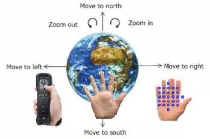
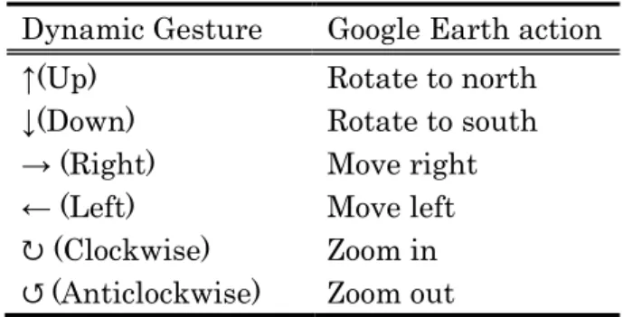
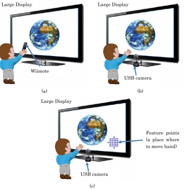
The system recognizes six dynamic gestures; up, down, right, left, clockwise circle and anticlockwise circle. Table 5.1 shows the corresponding Google Earth actions to each gesture. The system enables user to navigate in Google Earth through hand gesture and has three interfaces; sensor based, vision based (dynamic) and vision based (static). In sensor based interface, user holds Wiimote in his hand to perform gesture. In vision based (static) interface user moves his hand on the feature points area to perform a gesture. In vision based (dynamic) interface the bare hand performs a gesture (Figure 5.1 ).
Figure
Figure Figure
Figure 555....15111 Google Earth Hand Gesture Navigation SystemGoogle Earth Hand Gesture Navigation SystemGoogle Earth Hand Gesture Navigation System Google Earth Hand Gesture Navigation System
Table Table Table
Table 555....15111 Dynamic gesture and corresponding Google Earth actions Dynamic gesture and corresponding Google Earth actionsDynamic gesture and corresponding Google Earth actions Dynamic gesture and corresponding Google Earth actions Dynamic Gesture Google Earth action
↑(Up) Rotate to north
↓(Down) Rotate to south
→ (Right) Move right
← (Left) Move left
↻ (Clockwise) Zoom in
↺ (Anticlockwise) Zoom out
5.2 System Architecture
5.2.1 Hardware
The System`s hardware setting consists in a desktop computer and large display.
The large display we used has a size of 54 inches (Figure 5.2). Wiimote and Bluetooth adapters are used in sensor based interface for gesture recognition (Figure 5.2 (a)). The Wiimote, short for Wii Remote, is the primary controller for Nintendo Wii console. The Wiimote provides an inexpensive and robust packaging of several useful sensors, with the ability to rapidly relay the information to the computer. The Wiimote connects to a computer wirelessly through Bluetooth technology. A main feature of the Wiimote is its motion sensing capability, which allows the user to interact with and manipulate items on screen via gesture recognition.
Logitech Orbit AF Camera, capturing 640 x 480 resolution video with 30 FPS, 1024 x 768 for 15 FPS and 1600 x 1200 for 5 FPS, is used in vision based interfaces for gesture recognition (Figure 5.2 (b), (c)). A USB camera is constantly looking at the user and waiting for hand to perform gesture. In dynamic vision based interface, the recognizer detects users hand automatically (Figure 5.2 (b)). In case of the static vision based interface, the interface does not detect users hand by itself. Therefore, user has to move his hand inside the feature point area (Figure 5.2 (c)).
(a) (b)
(c) Figure
Figure Figure
Figure 5555....222 Google Earth Hand Gesture Navigation System hardware component: (a) 2Google Earth Hand Gesture Navigation System hardware component: (a) Google Earth Hand Gesture Navigation System hardware component: (a) Google Earth Hand Gesture Navigation System hardware component: (a) sensor based interface,
sensor based interface,sensor based interface,
sensor based interface, (b) vision based dynamic interface, (c) vision bases static interface(b) vision based dynamic interface, (c) vision bases static interface(b) vision based dynamic interface, (c) vision bases static interface(b) vision based dynamic interface, (c) vision bases static interface
5.2.2 Software
The system was implemented in Microsoft Windows platform. The system consists in two modules: recognizer and navigator. The gesture recognizer module was implemented in Visual C++ 2010 and OpenCV 2.2[19] image processing library.
The navigator module were implemented in Visual C# 2010 and Google Earth and Wiimote libraries are used. The gesture database is stored locally in file system.
The task of the recognizer module is to analyze hand motion and recognize gesture.
In sensor based interface, it processes hand motion signals and compares it Large Display
USB camera
Feature points (a place where to move hand) Large Display
Wiimote
Large Display
USB camera
against template values in gesture database. In vision based interface, the recognizer extracts hand from input image and then analyzes the hand motion along time frame to detect gesture. Navigator module then takes gesture value and performs corresponding Google Earth actions. The recognizer module works different in each interface. We describe each recognizer modules in detail in section 5.3.
In vision based interfaces, static and dynamic, we use OpenCV function named
“cvCalcOpticalFlowPyrLK”[19] to detect hand motion. This function takes positions of feature points to track as a parameter. In static vision based interface, the position of these feature points never changes but in the dynamic interface, this feature points changes with the hand motion simultaneously. That is why we call these two interfaces static and dynamic.
5.3 Gesture Recognizer module
5.3.1 Sensor Based Interface
Figure 5.3 shows the accelerometer signal processing and gesture recognition process of sensor based interface [15]. Gesture recognition process in sensor based interface has four steps. First, it records raw accelerometer data. Gesture starts when user pushes “A” button of Wiimote and stops when release the button.
During the push “A” period, accelerometer data will be recorded, temporarily.
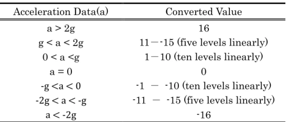
When gesture stops, the system preprocesses the signal, applying non-linear quantization (Table 5.3), which reduces length of input time series and converts acceleration data to discrete values.
Figure Figure Figure
Figure 555....35333 AcceleroAcceleroAcceleroAccelerometer Signal processing and gesture recognition processmeter Signal processing and gesture recognition processmeter Signal processing and gesture recognition processmeter Signal processing and gesture recognition process
Table Table Table
Table 5555....222 Non2NonNonNon----linear quantizationlinear quantizationlinear quantizationlinear quantization
Acceleration Data(a) Converted Value
a > 2g 16
g < a < 2g 11--15 (five levels linearly) 0 < a <g 1-10 (ten levels linearly)
a = 0 0
-g <a < 0 -1 - -10 (ten levels linearly) -2g < a < -g -11 - -15 (five levels linearly)
a < -2g -16
After the non-linear quantization, interface will calculate cost of the signal using Dynamic Time Warping (DTW) algorithm [15] (Figure 5.4) and then compare this value to all the pre-defined template values. DTW is an algorithm measures the similarity between two time sequences having different length (p = {p1, . . . , pn}
and q = {q1, . . . , qm}).
Figure Figure Figure
Figure 5555....444 Dynamic Time Warping (DTW) algorithm4Dynamic Time Warping (DTW) algorithmDynamic Time Warping (DTW) algorithmDynamic Time Warping (DTW) algorithm
Currently we have totally 18 pre-defined template values, three template values for each gesture.
5.3.2 Vision Based Interface (Static)
The optical-flow [23] denotes the movement of an image path between two frames of a video sequence that can measure the motion gesture even with high speed movement which is suitable for our scenario. There are various techniques for estimating the optical-flow, and it is proved efficient for gesture recognition.
Calculating the optical-flow in real-time for the whole image at 320 x 240 resolution might require a lot of computing power. Hand Gesture for Taking Self Portrait [18] proposed a different approach, a Cross Motion Interface, for hand motion tracking which is able to detect fast motion. We used the Cross Motion Interface [18] as itself in our static vision based Interface implementation. The Cross Motion Interface [18] restricts the optical-flow measurement with limited
feature points (29 points) and within a small region. The feature points movement will be extracted in each frame and calculating the mean value of both and speed.
The noise of small and large movement of feature points will be cut off, leaving only reliable movement among them. In order to recognize the gestures the interface analyze the pattern of feature points movement in video frame sequence, from no movement to movement, and to no movement, then distinguish a specific motion gesture. Optical-flow estimates are often very noisy. The layout of feature points affects the optical-flow measurement also; a circle-like layout are applied which proves effective for recognizing four motion directions. Figure 5.5 shows a frame sequence in video time line, that to recognizing a RIGHT hand motion.
(a) (b) (c) (d) (e) Figure
Figure Figure
Figure 5555....5555 Motion gesture time line [Motion gesture time line [Motion gesture time line [Motion gesture time line [18181818] a) frame t, no motion detected. b) frame t + 1, ] a) frame t, no motion detected. b) frame t + 1, ] a) frame t, no motion detected. b) frame t + 1, ] a) frame t, no motion detected. b) frame t + 1, motion orientation detected, the clock and arrow indica
motion orientation detected, the clock and arrow indica motion orientation detected, the clock and arrow indica
motion orientation detected, the clock and arrow indicate the motion orientation is right. c) te the motion orientation is right. c) te the motion orientation is right. c) te the motion orientation is right. c) frame t + 2, motion orientation is right. d) frame t + 3, motion orientation is r frame t + 2, motion orientation is right. d) frame t + 3, motion orientation is rframe t + 2, motion orientation is right. d) frame t + 3, motion orientation is r frame t + 2, motion orientation is right. d) frame t + 3, motion orientation is r
The four direction arrows indicate it can recognize four motion directions, left, right and up, down. Also, it can recognize clockwise and anticlockwise circle gestures.
When user uses a hand to make a cross motion within a specific short period, cross the interface, then the hand motion direction, UP, DOWN, LEFT and RIGHT, can be recognized by using optical-flow measurements. The interface cannot detect slow motion or continuous movement within the interface region. After performing gesture the user needs to stand still (no motion on the interface) for 20 milliseconds.
After that, a pattern of motion will be recognized.
5.3.3 Vision Based Interface (Dynamic)
Static vision based interface detects the motion of any moving objects over the feature points. Therefore, in order to give the hand more freedom of movement, we tried to detect only hand motion in dynamic vision based interface.
We detected open hand having five three to five fingers (Figure 5.6), since finger is most important feature of hand. We used this hand shape because hands do not have a fixed shape, and thus their shape is hard to describe computationally.
Figure
Figure Figure
Figure 5555....6666 Open HandOpen HandOpen HandOpen Hand
The gesture recognition process has three stages; hand detection, motion detection and gesture detection.
In this stage, we used skin-color based hand segmentation method. First we classified input image pixel in to skin-colored and non-skin-colored pixels [26], where a basic but adaptive skin color segmentation of a large interval of human skin varieties is performed. We used BGR color spaces (Table 5.3) which come from camera, since transforming BGR to other color spaces take time.
Table Table Table
Table 555....35333 BRG skin color spaceBRG skin color spaceBRG skin color space BRG skin color space
Space BGR
Param. R>95, G>40, B>20, max{R,G,B} - Min{R,G,B} < 15, abs(R-G)>15, R>G, R>B
After skin-color segmentation, an amount of noise pixels in the image is inevitable;
we apply median filtering to remove extraneous noise. Then we apply single connected component contour finding algorithm (implemented in OpenCV [19]) to locate hand contours (Figure 5.7 (a)). Our next job is to detect fingers in order to know whether that skin-colored object is hand or not. For that, we used convex hull based shape representation technique of OpenCV[19]. The convex hull of a shape is the smallest polygon that positions the entire points of the input shape
within the polygon. The shapes of the many complex objects are well characterizes by such defects. Figure 5.7 (b) illustrates a convexity defect on human hand image.
The convex hull is pictures as a blue line around the hand, pink points represent related defects on that convex hull.
(a) (b)
Figure Figure Figure
Figure 5555....777 Hand detection7Hand detectionHand detectionHand detection: (a) skin color segmentation, : (a) skin color segmentation, : (a) skin color segmentation, : (a) skin color segmentation, (b) convex hull based hand shape (b) convex hull based hand shape (b) convex hull based hand shape (b) convex hull based hand shape representation
representationrepresentation representation
We detected fingers by analyzing the distance and angles between defect points.
For that, first, we calculated angles between two defects. If the angle is less than 30 degrees we further calculated defect depth and length between two defects. We select a contour having three to five fingers as a hand candidate.
In order to track the hand motion, we used Optical Flow in OpenCV[19]. We tracked hand finger curves, the most stable points, to detect hand motion.
Figure 5.8 (a) shows not moving hand at time t, where hand curves are stable.
Figure 5.8 (b) shows a hand at time t+interval. In this case, the hand moved to left and point A is a point in frame t and point B is a point in frame t+interval.
(Interval =0.005 second)
(a) (b) Figure
Figure Figure
Figure 5555....8888 Optical Flow hand tracking: (aOptical Flow hand tracking: (aOptical Flow hand tracking: (aOptical Flow hand tracking: (a) not moving hand, (b) hand moving to left) not moving hand, (b) hand moving to left) not moving hand, (b) hand moving to left) not moving hand, (b) hand moving to left We used a direction from Point A to B to detect gesture. To calculate this direction, we divided the frame in to four parts; A, B, C, and D figure N (Figure 5.9).
If the point B falls in part A, we count it as a Up gesture. If it falls in part B we count is as a Down gesture. If it falls in part C we count it as a Right and part D as a left gesture.
Figure Figure Figure
Figure 555....95999 Recognizing GestureRecognizing GestureRecognizing Gesture Recognizing Gesture
Point A
Point B
A
B D C
5.4 Google Earth Navigator module
The task of the navigator module is to rotate the globe along the longitude, latitude and zoom in and zoom out. If navigator receives UP value from recognizer it changes the globe`s position +6 degrees along the latitude. If the gesture is DOWN the navigator changes the globe position -6 degrees along the latitude (Figure 5.10 (a)). If the gesture is RIGHT the navigator changes the globe position +6 degrees along the longitude. If the gesture is LEFT the navigator changes the globe position -6 degrees along the longitude (Figure 5.10 (b)). If the gesture is ZOOM IN the navigator increases current range by one over ten of current range along the altitude. If the gesture is ZOOM OUT the navigator decreases current range by one over ten of current range along the altitude (Table 5.10)
(a) (b)
Figure Figure Figure
Figure 555....105101010 Latitude and LongitudeLatitude and LongitudeLatitude and Longitude of Earth: (a) North Latitude and Longitudeof Earth: (a) North of Earth: (a) North of Earth: (a) North ↔ South navigation, (b) Left ↔ South navigation, (b) Left ↔ South navigation, (b) Left ↔ South navigation, (b) Left
↔Right navigation
↔Right navigation↔Right navigation
↔Right navigation Table
Table Table
Table 5555....4444 Google Earth Actions corresponds to each gestureGoogle Earth Actions corresponds to each gestureGoogle Earth Actions corresponds to each gestureGoogle Earth Actions corresponds to each gesture Gesture Google Earth Action
RIGHT Longitude +6
LEFT Longitude -6
UP Latitude +6
DOWN Latitude -6
ZOOM IN Current range* + current range*/10 ZOOM OUT Current range* - current range*/10
*Range is a distance between camera and globe UP (+6)
DOWN (-6)
LEFT (-6) RIGHT (+6)
Chapter 6
Evaluation
In this chapter we present the evaluation of Google Earth Hand Gesture Navigation system.
6.1 User evaluation
The purpose of our evaluation is to compare sensor based gesture recognition technique to vision based gesture recognition technique by studying user habit for gesture performance and user preference. We made two experiments; first one was made to compare Vision based interface (static) to Vision based interface (dynamic). Second one was made to compare Sensor based interface to the interface which has a best performance during the experiment 1.
6.1.1 Experiment 1
A total of 10 participants, 3 female and 6 male, joined the experiment 1, ages ranged from 22 to 37 years old. All participants are expert computer users. First, they were asked to perform six kinds of gestures to navigate through Google Earth.
We said participant which gesture to perform. User performed each gesture for three times randomly. Before the experiment start user was allowed to does some training for several minutes, until they get feel comfortable to the system. Then, we asked which interface they preferred and the reason for choosing that interface.
Also, we asked whether they felt any difficulty or not during the experiment and their opinion about the experiment and the system.
6.1.2
Results for experiment 1
During the experiment we measured two parameters; the accuracy and user preference. For testing the accuracy of Vision based static interface, we asked users to perform gestures and to see whether they are correctly recognized. The results are shown in tables 6.1 and 6.2. Left column of the table means user performed gestures and corresponding row is a result of recognized gestures, on average percentage.
Table Table Table
Table 6666....111 Vision based (static) interface accuracy1Vision based (static) interface accuracyVision based (static) interface accuracyVision based (static) interface accuracy
Up Down Left Right Zoom in Zoom out None
Up 80% 3% 7% 0 0 0 10%
Down 0 87% 7% 3% 0 0 3%
Left 0 3% 83% 0 0 0 13%
Right 0 0 0 87% 0 0 13%
Zoom in 0 3% 0 0 67% 0 30%
Zoom out 0 0 0 0 10% 53% 37%
Table Table Table
Table 666....26222 Vision based (dynamic) interface accuracyVision based (dynamic) interface accuracyVision based (dynamic) interface accuracy Vision based (dynamic) interface accuracy
Up Down Left Right Zoom in Zoom out None
Up 100% 0 0 0 0 0 0
Down 0 97% 0 0 0 0 3%
Left 0 0 77% 0 0 0 23%
Right 0 0 0 83% 0 0 17%
Zoom in 0 0 0 0 97% 0 3%
Zoom out 0 0 0 0 0 73% 27%
To know the user preference, we simply asked from the participants which interface they preferred and the reason for choosing that interface. We also asked the difficulty they experienced during the experiment and any other comments.
In this experiment eighteighteight students (80%)eight students (80%)students (80%) preferred Static Optical Flow interface students (80%) and the other two students (20%)two students (20%)two students (20%)two students (20%) preferred Static Optical Flow Interface. We summarized the user comments in tables 6.3 and 6.4
Table Table Table
Table 6666....3333 User comments for stUser comments for stUser comments for static interfaceUser comments for static interfaceatic interface atic interface
I prefer static interface, because: Number of students
Robust 2
Fast 2
User gets feedback 2
Zoom in/out works so good 1
Hands do not get tired 1
I do not prefer static interface, because: Number of students Hand cannot move freely and user has to be careful to
move his hand inside the feature point area
6
Zoom in/out gesture is difficult to perform 2
The interface recognizes all movement which produces some unwanted commands.
2
Not so robust 1
Left/Right gesture is difficult 1
Other comments Number of students
Using two hand gestures by applying the feature points in two places may be interesting
1
Table Table Table
Table 6666....444 User comments for dynamic interfac4User comments for dynamic interfacUser comments for dynamic interfacUser comments for dynamic interface
I prefer dynamic interface, because: Number of students
Freedom of hand movement 6
Detects only hand motion 2
More practical and natural 2
Interaction is easy to understand 1
I do not prefer static interface, because: Number of students User have to show his all five fingers precisely, that is
difficult
4
No feedback 3
Not robust 2
Zoom/out gesture is difficult 2
It was difficult to pay attention for not overlapping my hand on my face
1
Hand gets tired 1
Other comments Number of students
This kind of interaction is appropriate for the applications like Google Earth navigation
8
Showing cursor which points hand position on screen is urgently needed
3 Using Kinect will improve the accuracy much better 1
6.1.3 Experiment 2
Based on the result of experiment 1, we chose Dynamic Optical Flow interface as a candidate for the experiment 2, since 80% of the participants preferred this interface.
A total of 10 participants joined the experiment 2, 5 female and 5 male, ages ranged from 24 to 35 years old. Participants of experiment 2 are completely new people to experiment 1. Seven participants are expert computer users and the remaining three have basic operation skill. During the experiment participants did two types of tasks. First task is same as the task of experiment 1. Second task is Google Earth navigation task from Africa to Japan and we measured the duration and gesture step during the navigation process. Then, we asked from participants, which interface they preferred and reason for that. Also, we asked whether they felt any difficulty during the experiment or not and their opinion about the experiment and the system.
6.1.4 Results for experiment 2
Task 1 was made to measure the accuracy of each interface. For that, we asked users to perform gestures and to see whether they are correctly recognized. The results are shown in tables 6.5 and 6.6. Left column of the table means user performed gestures; corresponding row is result of recognized gestures, on average percentage.
Table Table Table
Table 6666....555 Sensor interfa5Sensor interfaSensor interfaSensor interface accuracyce accuracyce accuracyce accuracy
Up Down Left Right Zoom in Zoom out
None
Up 100% 0 0 0 0 0 0
Down 0 60% 37% 0 3% 0 0
Left 0 0 77% 13% 0 0 0
Right 0 0 10% 90% 0 0 0
Zoom in 3% 0 0 13% 83% 0 0
Zoom out 0 0 7% 3% 7% 93% 0
Table Table Table
Table 666....66666 ViViVision based (dynamic) interface accuracyVision based (dynamic) interface accuracysion based (dynamic) interface accuracy sion based (dynamic) interface accuracy Up Down Left Right Zoom in Zoom
out
None
Up 100% 0 0 0 0 0 0
Down 0 97% 0 0 0 0 3%
Left 0 0 90% 0 0 0 10%
Right 0 0 0 100% 0 0 0%
Zoom in 0 0 0 0 87% 0 13%
Zoom out 0 0 0 0 13% 73% 13%
In the task 2 we measured the duration and step of the gesture during the navigation from Africa to Japan. Table 6.7 shows the average of duration and step for each interface.
Table Table Table
Table 6666....777 Average duration and step for navigating fr7Average duration and step for navigating frAverage duration and step for navigating frAverage duration and step for navigating from Africa to Japanom Africa to Japanom Africa to Japanom Africa to Japan Sensor based
interface
Vision based interface (Dynamic)
Duration 43 sec 39 sec
Step 32 10
Four students Four students Four students
Four students (40%)(40%)(40%)(40%) preferred the Sensor based interface and another sixsixsixsix studentsstudentsstudentsstudents (60%)
(60%) (60%)
(60%) preferred Dynamic Optical Flow interface. We summarized the reason and user difficulties they experienced during the experiment 2 in table 6.8 and 6.9


![Figure 5.3 shows the accelerometer signal processing and gesture recognition process of sensor based interface [15]](https://thumb-ap.123doks.com/thumbv2/123deta/6096533.2082969/28.892.187.705.830.1020/figure-accelerometer-signal-processing-gesture-recognition-process-interface.webp)