Peak Search Algorithm for Frequency Analysis of Nonlinear Circuits
Hiroshige Kataoka Yoshihiro Yamagami Yoshifumi Nishio (Tokushima University)
1. Introduction
The circuit elements in the real world should con- tain nonlinear characteristics. The SPICE can treat nonlinear elements, however the standard method of SPICE cannot obtain frequency characteristics easily.
In this study, we propose a method to analyze nonlin- ear circuits and to obtain the peaks of the frequency characteristics of the circuit by using the sine-cosine circuits [1] and the ABM function of SPICE. Com- puter simulation results for a ladder circuit including nonlinear capacitors show that the proposed method can successfully obtain the peak frequencies.
2. Nonlinear Capacitor
The characteristic of the electric current which flows through a capacitor can be indicated as
𝑖 = 𝑑𝑞/𝑑𝑡 = (∂𝑞/∂𝑣)(𝑑𝑣/𝑑𝑡) (1) From this, the characteristic of a nonlinear capacitor is expressed with an expression using 𝑞 and 𝑣 as Eq. (2).
𝑣 = 𝐺(𝑞) = 𝑎𝑞 + 𝑏𝑞 2 + 𝑐𝑞 3 (2) We expand 𝑖, 𝑞 and 𝑣 to Fourier series, and obtain the coefficients of the voltages by using the trapezoidal formula as follows.
𝑉 2𝑘−1 = 1/𝜋
∫ 2𝜋
0 (𝐺(𝑞) cos 𝑘𝜃)𝑑𝜃
= (1/2𝐾)(𝐺 0 + 𝐺 2𝐾 ) + (1/𝐾)(𝐺 1 cos 𝑘𝜃 1
+𝐺 2 cos 𝑘𝜃 2 + ... + 𝐺 2𝐾−1 cos 𝑘𝜃 2𝐾−1 )(3)
𝑉 2𝑘 = 1/𝜋
∫ 2𝜋
0 (𝐺 (𝑞) sin 𝑘𝜃)𝑑𝜃
= (1/𝐾)(𝐺 1 cos 𝑘𝜃 1
+𝐺 2 cos 𝑘𝜃 2 + ... + 𝐺 2𝐾−1 cos 𝑘𝜃 2𝐾−1 )(4)
3. Simulation Result
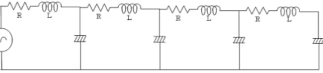
Figure 1: Circuit model. 𝐿=0.1[H] 𝑅 =0.1[Ω] (for low Q) and 0.055[Ω] (for high Q). Capacitor is linear 𝐶=1.0[F] or nonlinear 𝐺(𝑞) = 𝑞 + 0.8𝑞
3.
The circuit model is shown in Fig. 1. The circuit is forth-order RLC ladder circuit. We consider the cases that the capacitors are linear and nonlinear and the resistors are large (low Q) and small (high Q).
Figure 2 shows the sine-cosine circuit for this circuit model. Figures 3(a) and (b) show the obtained fre- quency characteristics for the cases of the linear and the nonlinear capacitors, respectively. After obtain- ing these frequency characteristics, we detect the peak values by using the algorithm combining the differen- tiator and the nonlinear limiter [2]. The peak values for nonlinear and high Q are obtained as Peak 1 = 0.998, Peak 2 = 0.720, and Peak 3 = 0.361.
Figure 2: Sine-cosine circuit.
(a) (b)
Figure 3: Frequency characteristics. (a) Case for linear capacitor. (b) Case for nonlinear capacitor.
4. Conclusions
In this study, we have proposed a peak search algo- rithm for nonlinear circuits. Simulation results showed that the proposed algorithm could detect peak values of the nonlinear ladder circuit.
References
[1] J. Kawata, Y. Taniguchi, M. Oda, Y. Yam- agami, Y. Nishio and A. Usida, “Spice-Oriented Frequency-Domain Analysis of Nonlinear Elec- tronic Circuits,” IEICE Trans. Fundamentals, vol.E90-A, no.2, pp.406-410, 2007.
[2] A. Kusaka, T. Kinouchi, Y. Yamagami, Y. Nishio and A. Ushida, “A Spice-Oriented Frequency Domain Analysis of Electromagnetic Fields of PCBs,” Proc. of NCSP’09, pp.526-529, 2009.
平成21年度電気関係学会四国支部連合大会