LETTER
Propagation-Delay Based Cyclic Interference Alignment with One Extra Time-Slot for Three-User X Channel
Feng LIU†a), Shuping WANG†, Shengming JIANG†,Nonmembers,andYanli XU†,Member
SUMMARY For the three-user X channel, its degree of freedom (DoF) 9/5 has been shown achievable theoretically through asymptotic model with infinite resources, which is impractical. In this article, we explore the propa- gation delay (PD) feature among different links to maximize the achievable DoF with the minimum cost. Since perfect interference alignment (IA) is impossible for 9 messages within 5 time-slots, at least one extra time- slot should be utilized. By the cyclic polynomial approach, we propose a scheme with the maximum achievable DoF of 5/3 for 10 messages within 6 time-slots. Feasibility conditions in the Euclidean space are also deduced, which demonstrates a quite wide range of node arrangements.
key words: interference alignment, three-user X channel, propagation delay, time-slot, degree of freedom
1. Introduction
The X channel has attracted increasing attentions in recent years, since independent and full message transmission be- tween any transmitter and receiver is possible. From the perspective of degree of freedom (DoF) indicating the pre- log factor of the capacity, [1] shows that the sum DoF of the M ×N X network with single-antenna nodes is equal toM N/(M+N−1). The key method of the achievability proof is interference alignment (IA), which can be imple- mented in spatial domain with multiple antenna support such as[2],[3], or in temporal domain exploiting propagation de- lay (PD) property such as[4]for the two-user X channel (i.e.
M=N=2).
It has been shown that when M ≥ 3 and N ≥ 3, no perfect IA exists in temporal domain [5] and asymptotic method with infinite symbol extension model is often used to achieve the upper-bound on DoF[1]. In fact, this implies that the DoF upper-bound is not achievable in practice where the available signal space is limited.
As temporal domain is the basic resource which can be always utilized when other kinds of resources are un- available, we focus on this aspect in the following content.
Besides the 2-user X channel,[4]also gives cyclic IA with polynomial model for PD-basedKuser interference channel.
In[6], we propose the implement of prefect IA based on PD with a DoF of 2K/(K+1) forK ×2 X channel and give the corresponding feasibility condition in Euclidean space.
Further detail of node placements is demonstrated in[7].
The three-user X channel represents the minimal num- Manuscript received November 26, 2018.
Manuscript revised February 10, 2019.
†The authors are with the College of Information Engineering, Shanghai Maritime University, Shanghai, China.
a) E-mail: [email protected] DOI: 10.1587/transfun.E102.A.854
ber ofMandNwith imperfect IA and needs further investi- gations. In this article, we address this issue by exploiting the PD feature among different links to maximize the achievable DoF with the minimum cost of transmission delay. Since perfect IA is impossible for the required 9 messages within 5 time-slots, at least one extra time-slot should be utilized.
By the cyclic polynomial approach, we propose an advanced scheme with the maximum achievable DoF of 5/3 for 10 messages within 6 time-slots. Also, we give its feasibility conditions in Euclidean space along with examples.
2. System Model
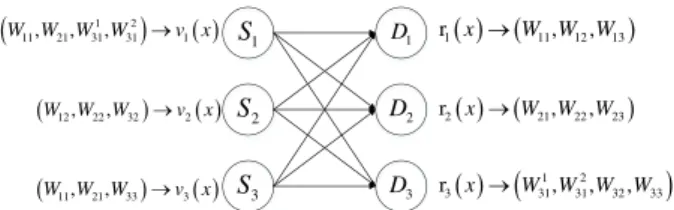
The three-user X channel model is shown in Fig. 1, where the three transmitters and three receivers equipped with sin- gle antenna are denoted by S1, S2, S3, D1, D2 and D3, respectively. Wi j denotes the desired message from trans- mitterSj to receiverDi, andτi j represents the PD between transmitter Sj to receiver Di. vj andri indicate the poly- nomials transmitted at Sj and received atDi, respectively.
The channel between each pair of transmitter and receiver is equally divided into time-slots with unit length. With- out loss of generality, all messages are normalized into one time-slot. The PD parameters are assumed to be static and non-negative integer multiples of one time-slot. Like the conventional orthogonal multiple-access schemes, the chan- nel access repeats itself afterntime-slots and new messages are transmitted cycle by cycle with a period ofn. In other words, messages are cyclically right-shifted over this PD- based channel. This procedure can be modeled by circular right-shift polynomial, with a period ofn.
Basic rule. For a messageWi j transmitted at an offset xsand delayed byttime-slots, the resulting message can be computed byx(s+t)Wi j mod(xn−1).
Encoding procedure. The code-word sent from Sj is encoded into the polynomialvj(x)by the encoding function
Fig. 1 System model of the three-user X channel with 10 independent messages.
Copyright © 2019 The Institute of Electronics, Information and Communication Engineers
to know the PD polynomial matrix defined by
D=* . ,
xτ11 xτ12 xτ13 xτ21 xτ22 xτ23 xτ31 xτ32 xτ33
+ / -
(3)
The input polynomial vector is defined by v = (v1(x), v2(x), v3(x)). Denote the received polynomial vector as r = (r1(x),r2(x),r3(x)). This linear system gives the following input-output relationship
rT ≡DvT mod(xn−1) (4)
where(.)T denotes the transpose of a vector. The received polynomialri(x)at the receiver is
ri(x)≡D(i,:)vT mod(xn−1) (5) whereD(i,:)indicates theithrow of matrixD.
Decoding procedure. The received polynomial is de- coded to obtain an estimate of the desired messages
fi :ri(x)→(Wi1,Wi2,Wi3) (6) For the above PD-based model, the achieved DoF is defined as the number of total messagesKover the periodn
DoF =K/n (7)
3. Proposed Scheme
By adding an extra time-slot to minimize the delay cost (i.e., n=6), we can not only transmit the original 9 messages, but also allow one more message delivered during each trans- mission period/cycle (i.e.,K =10). This is the largest value we can obtain with a period ofn = 6, since another extra message will cause a higher DoF than the upper bound due to 11/6>9/5 which is impossible.
Generally, exhaustive search among proper space can be used to obtain all potential schemes. However, this method has exponential complexity. Motivated by [6], we find a PD structure which can increase the DoF to 5/3. The ex- tra message is assumed from transmitterS1 to receiverD3. To distinguish them, we denote the two independent mes- sages from transmitter S1 to receiver D3 by W311 andW312, respectively.
maining task is to determine the offset parameters i jfor all the ten messages. Without loss of generality, we can send W11in the first time-slot, i.e., p11 = 0. Moreover, we can assume the transmitting ordering is as W11,W21,W311 and W312, i.e.,
0=p11<p21<p311 <p231≤5 (9) Sinceτ11=τ21=τ31=0, messagesWi1fromS1will occupy the same time-slots at each receiver.
AtD1, the index of time-slot forW11isp11=0, which should not be used by other messages. Sinceτ12=1, there is one offset of time-slots for messages from S2. Therefore, the last time-slot should not be occupied in each cycle at S2, otherwise the mod (x6 −1) operation will cause an interference in the coming time-slot 0. Since 0 ≤ pji ≤ n−1=5, we require
pj2 <5, ∀j=1,2,3 (10) At the same timeτ13=2, the time-slot offset for messages fromS3is two, which implies that
pj3,4, ∀j=1,2,3 (11) Similar analysis can be done atD2andD3. AtD2, the index of time-slot forW21isp21, which should not be used by other messages. Sinceτ22=5, there is 5 offset of time-slots for messages fromS2. To avoid interference atp21, we need
pj2+5,p21 mod 6, ∀j =1,2,3 (12) At the same timeτ13=4, the time-slot offset for messages fromS3is 4. The above requirement indicates
pj3+4,p21 mod 6, ∀j =1,2,3 (13) At D3, the indexes of time-slots forW311 andW312 are p311 andp231, respectively. Sinceτ32 =τ33 =0, there is no offset of time-slots for messages fromS2 andS3. To avoid interference atp131andp312 , we need
pj2,p311, pj2 ,p231, ∀j=1,2,3 (14) pj3,p311, pj3 ,p231, ∀j=1,2,3 (15) After checking the above constraints (9)–(15), we find a feasible solution of the offset of each message
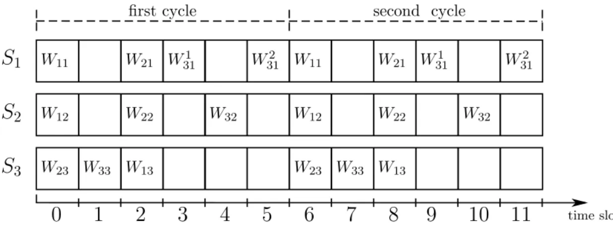
Fig. 2 Demonstration of the transmitting procedure within the first 12 time-slots.
p11=p12=p23=0, p33=1, p21=p22=p13=2, p113=3,
p32=4, p231=5 (16) Correspondingly, the transmitted polynomials are
v1(x)=W11+x2W21+x3W311 +x5W312 mod(x6−1) (17) v2(x)=W12+x2W22+x4W32 mod(x6−1) (18) v3(x)=W23+x1W33+x2W13 mod(x6−1) (19) Figure 2 shows the message offsets sent by the three transmitters in the first two cycles.
From (5) combined withn=6, the received polynomi- als can be computed as below. AtD1, we have
r1(x)≡D(1,:)vT mod(x6−1)
≡x0v1(x)+x1v2(x)+x2v3(x) mod(x6−1)
≡W11+x2W21+x3W311 +x5W312 +x1(W12+x2W22+x4W32)+x2(W23 +x1W33+x2W13) mod (x6−1)
≡W11+x1W12+x2(W21+W23) +x3(W311 +W22+W33)+x4W13 +x5(W312 +W32) mod(x6−1)
(20) Obviously, from (20) we can see that the desired messages W11,W12, andW13are located at the first, second, and fifth time-slots in each cycle without any interference, respec- tively. Moreover, all other interferences have been aligned in the other time-slots. Similarly, at receiverD2, we have
r2(x)≡D(2,:)vT mod(x6−1)
≡x0v1(x)+x5v2(x)+x4v3(x) mod (x6−1)
≡W11+x2W21+x3W311 +x5W312 +x5(W12+x2W22+x4W32)
+x4(W23+x1W33+x2W13) mod(x6−1)
≡(W11+W13)+x1W22+x2W21 +x3(W311 +W32)+x4W23
+x5(W312 +W12+W33) mod (x6−1) (21) From (21) the desired messagesW22,W21, andW23 are lo- cated at the second, third, and fifth time-slots in each cycle without any interference, respectively. Finally, the receiver D3yields
r3(x)≡D(3,:)vT mod(x6−1)
≡x0v1(x)+x0v2(x)+x0v3(x) mod (x6−1)
≡W11+x2W21+x3W311 +x5W312 +W12+x2W22+x4W32
+W23+x1W33+x2W13 mod(x6−1)
≡(W11+W12+W23)+x1W33 +x2(W21+W22+W13)
+x3W311 +x4W32+x5W312 mod (x6−1) (22) Equation (22) clearly indicates that the desired four messages W33,W311,W32andW312 are located at the second, fourth, fifth, and sixth time-slots in each cycle without any interference, respectively.
In summary, the task of sendingK =10 messages over n =6 time-slots has been completed by the above scheme, which verifies that the DoF of 5/3 is achievable.
Remark. We notify that the mod operation makes an effect of bringing the offset back into the integer range of [0,5], which indicates the circular right-shift of received
Fig. 3 Demonstration of the receiving procedure within the first 12 time-slots.
messages. To make it clear, we demonstrate it by Fig. 3, which shows the corresponding receiving procedure with respect to (20)–(22) within the first 12 time-slots (i.e., the first two cycles). Remember that the same pattern is repeated at each transmitter as depicted by Fig. 2. However, due to the PD property of the temporal channel, the messages transmitted in the same cycle may arrive at receivers over different cycles, which might cause a transient state before the stable state. Here the term ‘stable state’ means that the received messages show an exact repeated pattern, while transient state is the stage before that. For the proposed scheme, we can see a length of 4 time-slots (from time- slot 0 to 3) for the transient state. After that the receiving procedure of all receivers keeps in the stable state, which can be easily checked by the same pattern from time-slot 4. In detail, the received messages are exactly composed by the same messages in time-slotskandk+6,∀kwhen k ≥4.
For example, the received messages in time-slots 4 and 10 areW13,W23, andW32forD1,D2, andD3, respectively. This periodic receiving patten exhibits the cyclic property with a stable DoF of 5/3 over every 6 continuous time-slots from time-slot 4.
4. Feasibility in Euclidean Space
In this section we investigate the feasibility in two or three- dimensional Euclidean space for the above scheme. For the sake of simplicity, propagation speed v is assumed to be constant among all links, which means the PD feature also represents the distant relationship. The distance betweenSj andDi can be expressed by DiSj =v(τ0 +kτi j), where k is the scaling factor and τ0 is the reference origin of PD.
The PD increase in step ∆τ = 1 in our model indicates the corresponding equal distance increase with a step of
∆d =vk∆τ=vk, while the reference distance is denoted as d0 =vτ0. So we have the following conditions betweenSj andDi,∀i,∀j
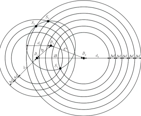
DiSj =d0+τi j∆d (23) According to the PD matrix (8), Fig. 4 depicts the equiv- alent geometric relationship among the transmitters and re- ceivers of the proposed scheme.
Denote the circle/sphere centered atDiwithSj on it by Oi(Sj). Geometrically, the feasibility conditions can be set up by making sure that the related circles/spheres have the desired intersection points for the node placements of all the three transmitters, which can be expressed as∀j=1,2,3
O1(Sj)∩O2(Sj)∩O3(Sj),∅ (24) In other words, eachSjshould locate at the intersection point of the three circles/spheresOi(Sj),∀i =1,2,3. The above constraint can be decomposed into the triangle relation by any two circles/spheres. Thus, if a node placement scheme is feasible, the side-length variablesa,b, andcof the triangle composed by any three nodes should satisfy the triangle inequality
|b−c| ≤ a ≤ b+c
|a−c| ≤ b ≤ a+c
|a−b| ≤ c ≤ a+b
(25)
For convenience, we denote the distance between D1 and D2 as a = D1D2, the distance between D1 and D3 as b = D1D3, and the distance between D2 and D3 as c =
Fig. 4 Feasibility demonstration in Euclidean space.
D2D3.
Firstly, we consider the scenario of each transmitterSj and any two receivers. ForD1andD2, the triangle inequal- ities are
|D1S1−D2S1| ≤ a ≤ D1S1+D2S1
|D1S2−D2S2| ≤ a ≤ D1S2+D2S2
|D1S3−D2S3| ≤ a ≤ D1S3+D2S3
(26)
for the triangles ∆S1D1D2, ∆S2D1D2, and ∆S3D1D2, re- spectively. Bringing (23) and (8) into (26), we can obtain
0 ≤ a ≤ 2d0 4∆d ≤ a ≤ 2d0+6∆d 2∆d ≤ a ≤ 2d0+6∆d
(27)
which can be further simplified as
4∆d ≤a ≤2d0 (28)
Similarly, the triangle inequalities give the range ofb as
2∆d ≤b≤2d0 (29)
and the range ofcas
5∆d ≤c≤2d0 (30)
The above conditions require
∆d≤2d0/5 (31)
Secondly, the triangle relation between the three re- ceivers can be further investigated. After some computa- tions, from (25) and (28)–(30) we have
max(4∆d,2d0−2∆d) ≤ a ≤ 2d0 max(2∆d,2d0−4∆d) ≤ b ≤ 2d0 max(5∆d,2d0−2∆d) ≤ c ≤ 2d0
(32)
On the other side, we can consider the scenario of each receiver Di and any two receivers. For convenience, we denote the distance between S1 and S2 as e = S1S2, the distance between S1 andS3 as f = S1S3, and the distance between S2 andS3 asg = S2S3. The above approach can be applied again. For example, withS1andS2, the triangle inequalities are
|D1S1−D1S2| ≤ e ≤ D1S1+D1S2
|D2S1−D2S2| ≤ e ≤ D2S1+D2S2
|D3S1−D3S2| ≤ e ≤ D3S1+D3S2
(33)
for the triangles∆S1S2D1,∆S1S2D2, and∆S1S2D3, respec- tively. Bringing (23) and (8) into (33), we can obtain
∆d ≤ e ≤ 2d0+∆d 5∆d ≤ e ≤ 2d0+5∆d
0 ≤ e ≤ 2d0
(34)
which can be further simplified as
5∆d ≤e≤2d0 (35)
Similarly, the triangle inequalities give the range of f
max(∆d,2d0−4∆d) ≤ g ≤ 2d0
We should remark that obviously the arbitrary choice of the reference distanced0and the scaling factork makes the feasibility conditions suitable to wide applications.
Here is an example. For underwater acoustic communi- cation, we often setv=1500m/s. Let the scaling factorkbe 0.02, 0.2, and 2, respectively. Then∆d=vkis 30 m, 300 m, and 3000 m, respectively. By (31) we have d0 ≥ 5∆d/2, which gives the lower bound on d0 as 75 m, 750 m, and 7500 m, respectively. The range ofa,b,c,e, f, andgcan be obtained by (32) and (38). Givenk=0.2 (i.e.,∆d=300m), the following network instances are provided for demonstra- tion.
(i) Whend0 =750 m, we have
1200 ≤ a ≤ 1500
300 ≤ b ≤ 1500
1500 ≤ c ≤ 1500
1500 ≤ e ≤ 1500
1200 ≤ f ≤ 1500
300 ≤ g ≤ 1500
(39)
wherec=e=1500 m is fixed.
(ii) Whend0 =3000 m, we have
5400 ≤ a ≤ 6000
4800 ≤ b ≤ 6000
5400 ≤ c ≤ 6000
5700 ≤ e ≤ 6000
5700 ≤ f ≤ 6000
4800 ≤ g ≤ 6000
(40)
Acknowledgments
This work was partially supported by the National Natural Science Foundation of China (No. 61271283, U1701265, 61472237, 61601283).
References
[1] V. Cadambe and S. Jafar, “Interference alignment and the degrees of freedom of wirelessXnetworks,” IEEE Trans. Inf. Theory, vol.55, no.9, pp.3893–3908, 2009.
[2] S. Jafar and S. Shamai, “Degrees of freedom region of the MIMO X channel,” IEEE Trans. Inf. Theory, vol.54, no.1, pp.151–170, 2008.
[3] M. Maddah-Ali, A. Motahari, and A. Khandani, “Communication over MIMO X channels: Interference alignment, decomposition, and per- formance analysis,” IEEE Trans. Inf. Theory, vol.54, no.8, pp.3457–
3470, 2008.
[4] H. Maier, J. Schmitz, and R. Mathar, “Cyclic interference alignment by propagation delay,” 2012 50th Annual Allerton Conference on Communication, Control, and Computing (Allerton), pp.1761–1768, IEEE, 2012.
[5] H. Maier and R. Mathar, “Cyclic interference alignment and cancella- tion in 3-user X-networks with minimal backhaul,” Information Theory Workshop (ITW), 2014 IEEE, pp.87–91, IEEE, 2014.
[6] F. Liu, S. Jiang, S. Jiang, and C. Li, “DoF achieving propagation delay aligned structure forK×2 X channels,” IEEE Commun. Lett., vol.21, no.4, p.897–900, 2017.
[7] S. Jiang, F. Liu, S. Jiang, and X. Geng, “A feasible distance aligned structure for underwater acoustic X networks with two receivers,”
IEICE Trans. Fundamentals, vol.E100-A, no.1, pp.332–334, Jan. 2017.