Study on Relay-Assisted Inter-Vehicle
Communication Techniques
for Advanced Intelligent Transport Systems
Le Tien Trien
Department of Communication Engineering and Informatics
Graduate School of Informatics and Engineering
THE UNIVERSITY OF ELECTRO-COMMUNICATIONS
A Dissertation Submitted in Partial Fulfilment
of the Requirements for the Degree of
Doctor of Philosophy
Study on Relay-Assisted Inter-Vehicle
Communication Techniques
for Advanced Intelligent Transport Systems
SUPERVISORY COMMITTEE:
Professor
Yasushi Yamao
Professor
Yoshio Karasawa
Professor
Sadao Obana
Professor
Takeo Fujii
Copyright © 2018 Le Tien Trien
All Rights Reserved
i
概要
近年,先進的なITS (Intelligent Transport Systems: 高度道路交通システム) のた めの通信技術への期待が高まっている.これには,車両がその位置や速度など の情報を交換する車車間通信,路側機が車両へ信号状態や道路規制などの情報 を提供する路車間通信,車両と歩行者の間で情報の交換を行う歩車間通信など がある.これらにブロードキャスト通信を活用することで,各車両では潜在的 な交通事故を予測して運転手に警告し,さらには制動を行うことにより事故を 未然に回避できる.さらにこの情報を利用して車両を自動制御することで,交 通流を意識した協調型自動走行を実現することが可能になるものと期待されて いる. 車車間通信を用いて安全運転支援およびより高度な自動走行システムを実現 するためには,高信頼,かつ低遅延の無線通信技術が要求される.しかしなが ら道路上の移動通信では,多重波伝搬によるフェージングや建物によるシャド ウイング,さらに自律分散通信システム特有の問題である隠れ端末問題による 干渉などの影響で,通信の信頼度が低下する.特に事故発生確率の高い交差点 ではその影響が顕著である. 本論文では車車間通信の品質を改善することを目的として,交差点等に中継 局 (Relay Station; RS) を設置し,車車間通信パケットを転送中継する中継アシス ト車車間通信に関する諸技術が提案されている.中継局は交差点付近の信号機 などに併設され,高いアンテナ高を有することと,他の車載局に対して見通し 内(Line-of-Sight; LOS) 伝搬環境にあるため,中継アシストシステムはシャドウ イングやフェージングの問題の軽減に有効であることが既に示されている.し かしながら,トラヒックが増加するにつれて中継局での輻輳問題が発生し,中 継効果が低下するという課題があった.そこで本論文では中継によるエアトラ
ii ヒックの増加を抑える方法として,中継送信時に複数のパケットペイロードを まとめて1つのパケットに再構成して送信するペイロード合成中継法を提案す る.本提案法により中継局での輻輳問題が解決でき,中継効果が向上すること を解析結果から明らかにした. 交差点における中継アシスト車車間通信のもう 1 つの課題として,中継局受 信時に隠れ端末問題の影響で受信成功率が低下することがある.この課題に対 しては中継局受信時にセクタアンテナを用いることが有効であることが示され ているが,本研究ではペイロード合成中継法にセクタ化受信を組合せたセクタ 化受信ペイロード合成中継法を提案し,その効果を理論解析およびシミュレー ションにより示した.セクタ化受信によって中継局での受信成功率を改善する と中継すべきパケット数が増加するが,提案法ではペイロード合成によって中 継パケットの送信効率を高めることができるので,結果として中継効果を高め て平均パケット伝送成功率を大幅に向上できることを明らかにした. さらに,複数交差点からなる市街地環境におけるセクタ化受信ペイロード合 成中継法の効果を,大規模ネットワークシミュレーションを用いてブロードキ ャスト配信成功率として総合的に評価した.他の車両および離れた中継局など 干渉源が複数存在する市街地環境においても,提案法を用いることによって隠 れ端末問題の影響が有効に回避できること,隣接する中継局間で互いに棲分け 中継をすることで非常に高い中継効果が得られることを明らかにした. 以上のように提案法は中継アシスト車車間通信の特性を大幅に改善できるが, 通信トラヒックがさらに高い環境に対処するため,中継パケットのエアトラヒ ックをさらに圧縮できる方法として,複数ノード環境に適したネットワークコ ーディング法を用いたペイロード合成中継法を提案する.本提案法では,車車 間ペイロードのソーティングと合成対象パケットの選択アルゴリズムによって 複数ノード環境でのネットワークコーディングの弱点を抑えつつ,輻輳問題に 有効に対処できることを示した.結果として本提案法をセクタ化受信と組合せ ることで,幅広い通信トラヒック条件においてブロードキャスト配信成功率が 大きく向上することを明らかにした.
iii
Summary
Wireless vehicular communications for advanced Intelligent Transport Systems (ITS) have the potential to support safety driving, enhance the efficiency of transportation and play an important role in the future automated driving system. The vehicle-to-vehicle (V2V), vehicle-to-infrastructure (V2I) and vehicle-to-pedestrian (V2P) communications in the advanced ITS enable safety support applications that can predict potential traffic accidents, warn drivers and, in some cases, directly control vehicles to prevent collisions. Such applications require highly reliable broadcast communications. However, the reliability of wireless communication in vehicular environments suffers from fast fading due to multipath propagation, shadowing, and distance-dependent path loss. In addition, hidden terminal (HT) problem is a great concern in CSMA/CA based wireless networks due to its distributed access nature. The packet delivery rate (PDR) of V2V communications rapidly decreases especially under non-line-of-sight (NLOS) environments such as intersections.
A vehicle-roadside-vehicle relay-assisted V2V communication scheme has been proposed to improve the reliability of V2V communications. In the scheme, packets sent from a vehicle can be directly received by other vehicles or relayed by a relay station (RS) to the other vehicles. Then path diversity effect can be obtained that improves PDR of V2V communications. However, when the V2V traffic becomes higher, the number of packets that RS has to retransmit becomes larger. This leads to a large number of packets waiting in the transmit queue of RS and packet congestion happens. If the normal relay scheme is employed, the packets may be dropped due to the limited queue size. Then the gain obtained by relay-assist may be decreased.
A packet payload combining relay (PCRL) scheme is proposed to deal with the congestion issue. In the scheme, multiple V2V packet payloads are combined into a single packet and the resultant packet is rebroadcasted once the channel becomes idle.
iv
Analytical and simulated results show that the proposed PCRL scheme can remarkably alleviate the congestion issue and improve the relaying performance.
The PCRL scheme, however, still suffers from HT problem. In the intersection environments where LOS propagation between VSs is often unavailable, the packet collision frequently happens due to HTs when RS receives V2V packets. If RS cannot receive V2V packets, the advantage of relay-assist becomes smaller. Therefore an improved PCRL scheme with sectorized receiving RS (SR-V2VC/PCRL) is proposed to mitigate the effect of HT problem as well as alleviating the congestion issue. An analytical model is then developed to analyze the performance of SR-V2VC/PCRL scheme considering a single intersection scenario. Numerical results show that the reliability of V2V communications is significantly improved by the proposed scheme.
Furthermore, performance of the SR-V2VC/PCRL scheme is discussed for an urban environment with multiple intersections. In such environment, RSs at intersections should cooperate with each other to obtain the largest diversity gain. After theoretically analyzing the performance of the sectorized receiving scheme under multiple interference sources, large-scale simulations are conducted to evaluate the performance of SR-V2VC/PCRL scheme. It is shown that the SR-V2VC/PCRL remarkably improves the reliability of V2V communications. SR-V2VC/PCRL scheme even performs better when employing higher data rate modulation for V2V and relay transmissions.
The aforementioned proposals can remarkably improve the reliability of V2V communications. In order to improve the performance of relay-assisted scheme when traffic load becomes even higher, a network coding (NC) based PCRL scheme (PCRL-NC) with a payload sorting and selection algorithm is proposed to adapt multiple node environment in an intersection. It is shown that the scheme can benefit from NC in alleviating the congestion issue while effectively mitigating the disadvantage of NC. As a result, the introduction of PCRL-NC to the proposed SR-V2VC/PCRL scheme can remarkably improve the reliability of V2V communications under various traffic environments.
v
Acknowledgment
I am using this opportunity to express my gratitude to everyone who supported me throughout the course. Foremost, I would like to express my sincere gratitude to my supervisor Professor Yasushi Yamao for the continuous support of my study and research, for his patience, immense knowledge. I have studied from him how to find and solve a research problem, and what we need to put our effort to. The experiences and knowledges I have after spending 6 years in Yamao lab will help me a lot for sure when I become an industrial researcher from April 2018. I also would like to thank my fellow lab-mates in Yamao, Fujii, Ishibashi and Adachi Labs for the stimulating discussions, for all the fun we have had in the last six years.
I would like to thank the Japanese Ministry of Education, Culture, Sports, Science and Technology (MEXT) for the financial support for 11 years since April 2007. Without the scholarship, I could not finish my PhD course.
I would like to thanks all my Vietnamese friends in UEC for encouraging me and supporting me so much. Sharing of child rearing and research is such a hard work, and I could not handle without the help from them. I also want to share my excitement with my best friends in Japan (Hai Anh, Hang, Hoan, Huy, Tien) for always being with me.
Last but not least, I would like to thank my family: my parents, Le Trong and Phan Thi Xuan, for giving birth to me and supporting me spiritually throughout my life, my sisters and my brother for their words of encouragement and supports. I would like to thank my wife, Le Thi Hang, for her special love and sacrifice. Especially, she gave me the most precious thing in my whole life: Kumon-kun. We live our life full of love and full of fun from the moment he said hello to the world.
vi
Contents
概要 ... i Summary ... iii Acknowledgment ... v Contents ... vi List of Figures... ixList of Tables ... xii
Acronyms ... xiii
Chapter 1. Introduction... 1
1.1 Research Background ... 1
1.2 Motivations and Contributions ... 4
1.2.1 Motivations ... 4
1.2.2 Contributions ... 7
1.3 Outline of the Dissertation ... 8
Chapter 2. Technical Background ... 10
2.1 Application Descriptions and Requirements for Communication ... 10
2.1.1 Safety Applications ... 10
2.1.2 Non-Safety Applications ... 12
2.2 IEEE 802.11p PHY/MAC Standard ... 13
2.2.1 Physical Layer Specification ... 13
2.2.2 MAC Layer Specification ... 14
2.3 Frequency Band Allocations ... 18
2.4 Radio Propagation Model for Intersections ... 20
2.4.1 Propagation Model for LOS ... 21
2.4.2 Propagation Model for NLOS ... 22
Chapter 3. Relay-Assisted V2V Communications with Payload Combining ... 23
3.1 Introduction ... 23
3.2 Packet Combining Relay (PCRL) Scheme ... 25
3.2.1 Packet Relay-Assisted V2V Scheme ... 25
3.2.2 Principle of PCRL Scheme ... 26
Contents
vii
3.2.4 Time Division Grouping (TDG) Method ... 30
3.3 Analysis Model ... 30
3.3.1 MAC Layer Service Time of RS ... 31
3.3.2 Expression of Packet Transmission Rate at RS ... 34
3.4 Numerical Results ... 35
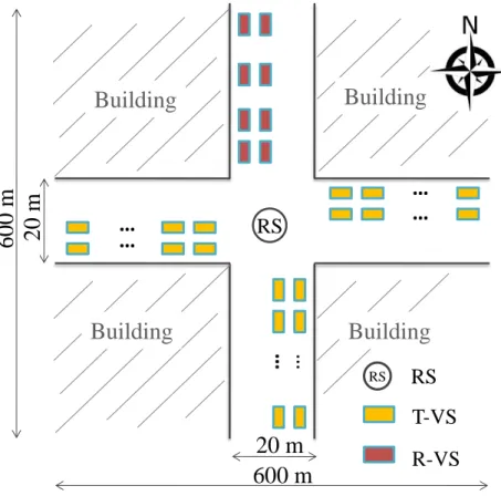
3.4.1 Vehicle Stations Layout and Evaluation Parameters ... 35
3.4.2 Packet Arrival Process at RS ... 38
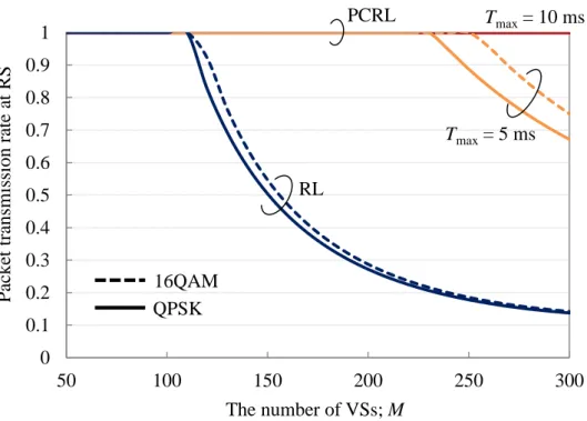
3.4.3 Packet Transmission Rate at RS ... 39
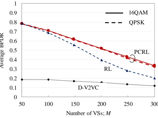
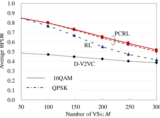
3.4.4 Broadcast Packet Delivery Rate (BPDR) ... 41
3.5 Chapter Summary ... 44
Chapter 4. An Improved Relay-Assisted V2V Communications with Packet Payload Combining and Sectorized Receiving ... 46
4.1 Introduction ... 46 4.2 V2V Communications System ... 48 4.2.1 R-V2VC Scheme ... 48 4.2.2 OR-V2VC/PCRL Scheme ... 48 4.2.3 SR-V2VC/PCRL Scheme ... 50 4.3 Performance Analysis ... 53
4.3.1 CSMA/CA collision model ... 53
4.3.2 PRR at RS and PDR at R-VS ... 53
4.3.3 Straight road scenario ... 55
4.3.4 Intersection Scenario ... 59
4.4 Numerical Simulation of Large-Scale System ... 65
4.4.1 Simulation set up ... 65
4.4.2 Simulation Results ... 67
4.5 Chapter Summary ... 72
Chapter 5. Packet Relay-Assisted V2V Communication Scheme with Multiple Relay Stations in Urban Environment ... 73
5.1 Introduction ... 73
5.2 Effect of Multiple RSs for SR-V2VC/PCRL Scheme in Urban Environment ... 75
5.2.1 PRR at RS5 Suffering from Interferences of Other RSs ... 75
5.2.2 Cooperation among Sectorized RSs ... 79
5.3 Effect of High Data Rate for V2V Communications ... 80
5.4 Evaluation by Simulations ... 82
5.4.1 Node Layout Model and Simulation Set Up ... 82
5.4.2 Simulation Results ... 84
viii
6.1 Introduction ... 93
6.2 SR-V2VC/PCRL-NC Scheme ... 95
6.2.1 Operational Principle ... 95
6.2.2 Effect of PCRL-NC Scheme in Mitigating Congestion Issue and Reducing CBR ... 97
6.2.3 Payload Sorting and Selection Algorithm ... 97
6.3 Evaluation by Simulations ... 98
6.3.1 Node layout and simulation set up ... 98
6.3.2 Packet Transmission Rate at RS ... 100
6.3.3 Average SDP ... 101
6.3.4 BPDR Performance ... 102
6.4 Chapter Summary ... 103
Chapter 7. Conclusions and Future Works ... 105
7.1 Conclusions ... 105
7.2 Future Works ... 107
References ... 109
List of Figures
ix
List of Figures
Fig. 1.1: Lack of safety confirmation is the most cause of accidents [3]. ... 2
Fig. 1.2: Advanced Safety Vehicle (ASV)... 2
Fig. 1.3: Traffic accidents happen most often in urban area, especially around intersection [3]. ... 5
Fig. 1.4: Outline of the dissertation. ... 9
Fig. 1.5: Technology map for this dissertation. ... 9
Fig. 2.1: IEEE 802.11p frame format ... 15
Fig. 2.2: IEEE 802.11 channel access method ... 16
Fig. 2.3: Hidden terminal (HT) problem ... 17
Fig. 2.4: ITS frequency bands allocation ... 19
Fig. 2.5: Frequency arrangement regarding 700 MHz range in Japan ... 20
Fig. 2.6: Definition of parameters for NLOS condition ... 22
Fig. 3.1: Relay-assisted V2V communications model ... 26
Fig. 3.2: Packet relay-assisted V2V communications schemes ... 27
Fig. 3.3: Frame format of combined packet. The number of payload combining k can be conveyed in PLCP service field. ... 28
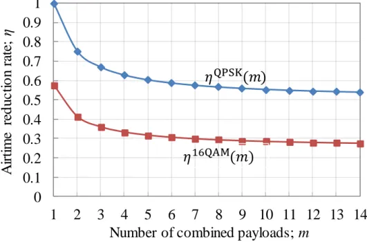
Fig. 3.4: Relationship between 𝜂 and k ... 29
Fig. 3.5: An example of linear TDG with four groups [52] ... 31
Fig. 3.6: Generalized state transition diagram for transmission process ... 33
Fig. 3.7: Node layout model ... 36
Fig. 3.8: Packet arrival process at RS (Tmax = 10 ms) ... 38
Fig. 3.9: Packet transmission rate at RS (Tmax = 10 ms) ... 40
Fig. 3.10: Impact of Tmax and modulation scheme ... 40
Fig. 3.11: Average BPDR from T-VSs on east and west streets ... 42
Fig. 3.12: Average BPDR from T-VSs on south street ... 42
Fig. 3.13: Average BPDR from T-VSs on all streets... 43
Fig. 3.14: Average BPDR from T-VSs on all streets with TDG ... 44
x
Fig. 4.3: Node layout model for straight road scenario ... 55
Fig. 4.4: PRR at RS under straight road environment ... 57
Fig. 4.5: PDR vs. location of I-VS (xT = 300 m, xR = 0 m) ... 58
Fig. 4.6: IVS-area averaged PDR vs. location of R-VS (xT = 300 m) ... 59
Fig. 4.7: Node layout model for intersection scenario ... 60
Fig. 4.8: PRR at RS under intersection environment ... 61
Fig. 4.9: PDR vs. location of I-VS when T-VS and R-VS are in LOS condition xR (xR = yR = 0 m, xT = 300 m) ... 62
Fig. 4.10: IVS-area averaged PDR vs. location of R-VS (xT = 300 m) ... 63
Fig. 4.11: PDR vs. location of I-VS when T-VS and R-VS are in NLOS condition (xR = 0 m, yR = 100 m, xT = 200 m) ... 64
Fig. 4.12: IVS-area averaged PDR vs. location of R-VS (xT = 200 m) ... 64
Fig. 4.13: Node layout for intersection environment ... 66
Fig. 4.14: Horizontal radiation pattern of sector antenna unit ... 67
Fig. 4.15: PRR at RS under intersection environment ... 68
Fig. 4.16: Effect of RS location on PRR at RS ... 69
Fig. 4.17: Effect of RS location on BPDR ... 69
Fig. 4.18: BPDR under intersection environment ... 70
Fig. 4.19: BPDR of SR-V2VC/PCRL with various FBR/FSR ... 71
Fig. 5.1: Analysis model ... 76
Fig. 5.2: Packet collision probability between VS and other VSs and between T-VS and RSs ... 78
Fig. 5.3: PRR at RS5 suffering from interferences of other RSs ... 79
Fig. 5.4: Effectiveness of high data rate in reducing overlapping probability ... 82
Fig. 5.5: Node layout model ... 83
Fig. 5.6: Block diagram of RS for SR-V2VC/PCRL scheme in urban scenarios ... 84
Fig. 5.7: PRR at RSs ... 85
Fig. 5.8: Performance of SR-V2VC/PCRL scheme ... 86
Fig. 5.9: Effect of covering radius at RSs ... 87
Fig. 5.10: Effect of covering radius at RSs under higher traffic conditions... 88
Fig. 5.11: Effect of employing high data rates for direct V2V communications ... 89
List of Figures
xi
Fig. 5.13: Average delivery delay of V2V communications ... 91
Fig. 6.1: PCRL schemes with and without NC ... 96
Fig. 6.2: Effectiveness of PCRL-NC scheme in reducing packet length ... 98
Fig. 6.3: Block diagram of RS for SR-V2VC/PCRL-NC scheme (G=4) ... 99
Fig. 6.4: Packet transmission rate at RS for PCRL schemes with and without NC . 100 Fig. 6.5: Average SDP ... 102
xii
List of Tables
Table 2.1: Examples of safety applications and the requirements [30-32] ... 12 Table 2.2: Parameters for PHY layers of IEEE 802.11a and IEEE 802.11p [14] ... 14 Table 2.3: Parameters for MAC layer of IEEE 802.11a and IEEE 802.11p ... 16 Table 2.4: Main candidate data rates for IEEE 802.11p based V2V communications
... 18 Table 3.1: Radio Transmission Parameters ... 37 Table 3.2: V2V Traffic Conditions ... 37
Acronyms
xiii
Acronyms
16QAM 16-Quadrature Amplitude Modulation
3GPP LTE 3rd Generation Partnership Project Long-Term Evolution 64QAM 64-Quadrature Amplitude Modulation
AAA American Automobile Association A-ITS Advanced Intelligent Transport Systems ARQ Automatic Repeat reQuest
ASV Advanced Safety Vehicle
BPDR Broadcast Packet Delivery Rate BPSK Binary Phase Shift Keying
BS Base Station
BSS Basic Service Set
CBR Channel Busy Ratio
CCA Clear Channel Assessment
CINR Carrier-to-Interference-and-Noise power Ratio
CS Carrier Sense
CSL Carrier Sense Level
CSMA Carrier Sense Multiple Access
CSMA/CA Carrier Sense Multiple Access with Collision Avoidance
CW Contention Window
DCF Distributed Coordination Function DIFS Distributed Inter Frame Space DOOR Dynamic Optimization On Range DOT Department of Transportation (U.S.) DSRC Dedicated Short-Range Communications D-V2VC Direct V2V communications
ETC Electronic Toll Collection
FBR Front-to-Back Ratio
FFT Fast Fourier Transform
FSR Front-to-Side Ratio
GPS Global Positioning System
xiv ISI Inter-Symbol Interference
I-VS Interfering Vehicle Station
LOS Line-Of-Sight
MAC Medium Access Control
NACK Negative-ACKnowledgement
NAV Network Allocation Vector
NC Network Coding
NHTSA US National Highway Traffic Safety Administration
NLOS Non-Line-Of-Sight
OBU On-Board Unit
OFDM Orthogonal Frequency-Division Multiplexing
ORA Omnidirectional Receive Antenna
OR-V2VC Relay-assisted V2V communications with omnidirectional
receiving RS
OR-V2VC/PCRL Relay-assisted V2V communications with omnidirectional receiving and payload combining
PCRL Packet Payload Combining ReLay
PCRL-NC Network Coding based Payload Combining ReLay
PDF Probability Density Function
PDR Packet Delivery Rate
PGF Probability Generating Function
PHY Physical Layer
PLCP Physical Layer Convergence Protocol
PRR Packet Reception Rate PTR Packet Transmission Rate
QPSK Quadrature Phase Shift Keying
RL Normal ReLay
RS Relay Station
RSSI Received Signal Strength Indicator
RSU Roadside Unit
RTS/CTS Request-To-Send/Clear-To-Send
RTTT Road Transport and Traffic Telematics
R-V2VC Relay-assisted V2V Communications R-VS Receiving Vehicle Station
SDP Successful Decoding Probability SRA Sectorized Receiving Antenna
Acronyms
xv
SR-V2VC Relay-assisted V2V communications with sectorized
receiving RS
SR-V2VC/PCRL Relay-assisted V2V communications with sectorized receiving and payload combining
SR-V2VC/PCRL-NC Relay-assisted V2V communications with sectorized receiving and network coding based payload combining
TDG Time Division Grouping
TDMA Time Division Multiple Access T-VS Transmitting Vehicle Station
UAV Unmanned Aerial Vehicle
V2I Infrastructure-to-Vehicle
V2V Vehicle-to-Vehicle
VS Vehicle Station
VSC Vehicular Safety Communications
WAVE Wireless Access in Vehicular Environment
WHO World Health Organization
WLAN Wireless Local Area Network
1.1 Research Background
1
Chapter 1.
Introduction
1.1 Research Background
World Health Organization (WHO) indicates that road traffic accidents annually cause more than 1.2 million deaths on the world’s roads and have a huge impact on health and development. They are the leading cause of death among young people aged between 15 and 29 years, and cost governments approximately 3% of GDP [1]. A study from the American Automobile Association (AAA) concluded that car crashes cost the U.S. 300 billion dollar per year [2]. While there has been progress in road safety legislation and in making vehicles safer, the pace of change has been too slow. Urgent action is thus needed to achieve the ambitious target for road safety: halving the global number of deaths and injuries from road traffic crashes by 2020. In Japan, although the number of deaths gradually decreases in recent years, it still keeps much higher than 2,500, a target number set by Japanese government. The government is aiming to reduce annual road fatalities to that or less by 2018.
According to the Japanese national police agency, the lack of safety confirmation by driver is the most cause of traffic accidents (Fig. 1.1), which leads to delay in controlling the vehicle [3]. Advanced Safety Vehicle (ASV) has been developed for years in Japan to prevent accidents caused by driver oversight due to low visibility or inattention. ASV is a joint initiative involving industry, academia and government, and headed by the Japanese Ministry of Land, Infrastructure, Transport and Tourism [4]. By employing advanced Intelligent Transport Systems (A-ITS) that consists of varieties of technologies based on electronics, sensors, wireless communications and artificial intelligence (AI), ASV can recognize surrounding environment, provide drivers with information on potential hazards such as the approach of vehicles and pedestrians, and support drivers even when visibility is low (Fig 1.2). In some cases, ASV can directly control the vehicle to avoid collisions.
2
Source: Japan national police agency.
Fig. 1.1: Lack of safety confirmation is the most cause of accidents [3].
Source: http://www.mlit.go.jp/jidosha/anzen/01asv/resourse/data/asv5pamphlet.pdf
Fig. 1.2: Advanced Safety Vehicle (ASV)
2006 2007 2008 2009 2010 2011 2012 2013 2014 2015 2016 Year N u m b er o f traf fi c acc id en ts 280 000 240 000 200 000 160 000 120 000 80 000 40 000
Lack of safety confirmation
Inattentive driving
1.1 Research Background
3
To enable information exchange between vehicles and roads for preventing potential accidents, wireless communication is the essential means in A-ITS. According to the U.S. Department of Transportation (DOT), vehicular communication systems potentially address about 80 % of all-vehicle target crashes [5]. In Japan, more than 70 % of the accidents are due to rear-end collision, collision at intersection as well as left-turn and right-turn collisions [3]. These types of crashes can be potentially alleviated by employing vehicle-to-vehicle (V2V) and infrastructure-to-vehicle (V2I) communications.
Besides traffic safety improvements, vehicular networks have several other benefits that can be achieved by real-time data processing. Examples include congestion detection and avoidance, travel-time estimation, route guidance and cooperative driving. These services can save both time and fuel and therefore they have significant economic advantages. Furthermore, vehicular communications have been supposed to play an important role in the future automated driving systems [6].
Many efforts have been done in the area of vehicular communications for safety support applications. In 1999, the U.S. Federal Communication Commission allocated 75MHz of Dedicated Short-Range Communications (DSRC) spectrum at 5.9 GHz to be used exclusively for V2V and V2I communications [7]. In 2004, a task group was formed in order to develop a standard for wireless access in vehicular environment (WAVE). By 2010, the IEEE 802.11p standard was approved by IEEE as a PHY/MAC protocol for DSRC [8]. It is modified from the IEEE 802.11a standard and encompasses enhancements to the physical (PHY) and medium access control (MAC) layers to address communications in vehicular environments. The PHY layer is based on orthogonal frequency-division multiplexing (OFDM), and the MAC layer uses a carrier sense multiple access (CSMA) scheme to control access to the transmission medium. The operational functions and complexity related to DSRC are handled by the upper layers of the IEEE 1609 set of standards, which define how applications that utilize WAVE will function in a vehicular environment. More specifically, IEEE P1609.1 [9] defines management activities, while IEEE P1609.2 [10] defines security protocols, and IEEE P1609.3 [11] defines networking protocols. The IEEE 1609.4 [12] covers definitions and recommendations for multi-channel operation. In Japan, instead of the 5.8 GHz band, which is currently used for ETC (Electronic Toll Collection) system, the
4
band of 760 MHz was allocated for V2V and V2I communications [13]. In 2012, ARIB STD-T109 was established as a standard for V2V and V2I communications [14]. It uses the same physical layer with IEEE 802.11p, but employs a modified MAC layer that mixes CSMA/CA (Carrier Sense Multiple Access with Collision Avoidance) with time slotted access to share the single channel by V2V and V2I communications.
Another candidate technology for vehicular communications is long-term evolution (LTE)-Advanced standardized by 3rd generation partnership project (3GPP). In the
infrastructure-based LTE approach, each vehicle station (VS) in a cell transmits its beacon message in the uplink channel to the base station (BS). Then the BS retransmits the beacon in the downlink channel to other intended recipients [15].
1.2 Motivations and Contributions
1.2.1 Motivations
This dissertation focuses on V2V communication that employs the IEEE 802.11p standard, which is ready and validated for deployment after around 10 years of researches, tests and field trials. In December 2016, the US National Highway Traffic Safety Administration (NHTSA) proposed to mandate IEEE 802.11p based DSRC for all new light vehicles [16].
In IEEE 802.11p based V2V communications for safety support applications, the reliability of communications is the most important performance requirement. In ARIB STD-T109 [14], it is specified that cumulative packet reception rate should satisfy 95 % while a vehicle moves 10 m (or 5 m when GPS accuracy level becomes better in the near future). If vehicle speed is 60 km/h, there are only triple chances of the reception during the move of 5 m. Then reliability of each reception should keep more than 63.2 %. More reliable communication will be required for the future automated driving systems. For example, the cumulative packet reception rate should satisfy 99 % while a vehicle moves 5 m. However, the reliability of wireless communications is severely affected by distance dependent path loss, shadowing, and fast fading caused by multipath propagation. It is known that the packet delivery rate (PDR) from transmitting VS (T-VS) to receiving VS (R-VS) of direct V2V communications (D-V2VC) rapidly
1.2 Motivations and Contributions
5
deteriorates under non-line-of-sight (NLOS) environments such as intersections [17]. Furthermore, a hidden terminal (HT) problem is a great concern in CSMA/CA based wireless network due to its distributed access nature [18]-[19]. In V2V communications, buildings around corners not only reduce the communication range but also cause HT problem. Thus, it is difficult for the D-V2VC to achieve reliable communications near intersections.
This dissertation focuses on improving the reliability of V2V communications for ITS safety support applications considering intersection scenarios. The reason to focus on intersections is most of the accidents happen around intersections in urban area as shown in Fig. 1.3. There are several approaches proposed in the literatures to improve the reliability of V2V communications. In [20], a simple retransmission scheme is proposed to combat HT problem and improve the reliability of V2V communications. In the scheme, a receiver that identifies a collision process sends a NACK signal back to the senders to require retransmissions. In [21], another retransmission scheme using network coding is proposed. The scheme combines multiple V2V packets that were transmitted by different vehicles into a single retransmission by using the concept of network coding. In [22], a message rate adaptation, which adjusts the transmit rate and/or transmit power for the beacon messages is proposed. The scheme can control the channel load below a certain threshold, and thus effectively to mitigate congestion in V2V communications. In [23] and [24], system parameters such as transmit power and
Source: Japan national police agency.
Fig. 1.3: Traffic accidents happen most often in urban area, especially around intersection [3]. 2006 2007 2008 2009 2010 2011 2012 2013 2014 2015 2016 Year N u m b er o f traf fi c acci d en ts 400 000 150 000 350 000 300 000 250 000 200 000 100 000 Intersections Straight roads Straight roads Intersections Urban area
Other than urban area 50 000
6
carrier sensitivity are adaptively adjusted according to the environments. Although all the works intend to improve the reliability of V2V communications, their effectiveness in intersection scenarios are not clear. At intersections, corners are often occupied by buildings, which may block line-of-sight (LOS) paths and severe shadowing loss hinders communications between vehicles. Under this circumstance, successful delivery of safety related messages by the direct V2V communications is challenging.
In order to overcome the shadowing problem in NLOS situations such as intersections, the utilization of parked vehicles as relay nodes has been proposed in [25]. The effect of obstacles can be mitigated through the packet retransmission by the parked car around the intersections. However, it is not guaranteed that a parked vehicle exists around the intersection. Furthermore, even if there is any parked car, it cannot be utilized if its engine is turned off. In [26], unmanned aerial vehicles (UAVs) are introduced to relay packets between vehicles on the ground. Another approach is the utilization of roadside units (RSUs) as a relay station (RS). In [17], a relay-assisted V2V communications (R-V2VC) scheme has been proposed, which does not require any modification to IEEE 802.11p protocol. In R-V2VC scheme, an RS that has LOS links to two communicating VSs assists the communication. By compensating the large path loss and obtaining the path diversity effect, the PDR of V2V communications improves [17].
However, two main issues prevent the R-V2VC scheme from achieving high reliability. First, packet congestion happens at RS that limits the performance improvement by relay-assist. As traffic becomes higher, the number of packets that RS has to retransmit becomes larger. This leads to a large number of packets waiting in the transmit queue of RS. If the normal relay scheme is employed, the packets may be dropped due to the limited queue size. If the packet drop happens, the gain obtained by relay may be decreased. Consequently, it is crucial to introduce a kind of traffic congestion avoidance methods to RS. Second, R-V2VC scheme still suffers from HT problem, which limits the performance of relay-assist. When RS is located around intersections where LOS propagation between VSs is often unavailable, the packet collision frequently happens at RS due to HTs because VSs cannot carrier sense each other. If packet collision happens at RS, the advantage of R-V2VC becomes smaller.
1.2 Motivations and Contributions
7
In addition, in actual environments, multiple RSs may coexist, e.g., each RS is installed at each intersection in urban area. In such a case, to obtain the maximum diversity effect among RSs while minimizing the drawback such as packet congestion due to relayed packets from multiple RSs, a sophisticated RS cooperation scheme should be developed.
1.2.2 Contributions
The main contributions of this dissertation are as follows.
1) A packet payload combining relay (PCRL) scheme is proposed to deal with the congestion issue at RS. In the scheme, multiple V2V packet payloads are combined into a single packet and the resultant packet is rebroadcasted once the channel becomes idle. Analytical and simulated results show that the proposed PCRL scheme can remarkably alleviate the congestion issue and improve the relaying performance.
2) An improved PCRL scheme with sectorized receiving RS (SR-V2VC/PCRL) is proposed in order to alleviate the congestion issue as well as mitigate the effect of HT problem. A theoretical model is derived to evaluate the performance of the proposed scheme considering both straight street and intersection scenarios. The model takes into account the effect of multiple HTs and fading. Numerical results show that the reliability of V2V communications is significantly improved by the proposed scheme.
3) Performance of the proposed SR-V2VC/PCRL scheme is evaluated in an urban scenario that consists of multiple intersections. The employed performance metric is broadcast packet delivery rate (BPDR). After theoretically analyzing the effectiveness of the sectorized receiving scheme under multiple interference sources, large-scale simulations are conducted to evaluate performance of SR-V2VC/PCRL scheme. It is shown that the SR-SR-V2VC/PCRL remarkably improves BPDR of V2V communications. SR-V2VC/PCRL scheme even performs better when employing higher-order modulation for V2V communications and relay transmission.
8
4) A highly reliable network coding (NC) based PCRL scheme with a payload sorting and selection algorithm (PCRL-NC) is proposed to solve the congestion issue at RSs due to the increased traffic in urban environments. The proposed PCRL-NC for SR-V2VC scheme (SR-V2VC/PCRL-NC) is evaluated by theoretical analysis and large-scale simulations. Numerical results show that by employing the proposed algorithm for the encoding process, the disadvantage of normal NC is alleviated while the congestion issue is effectively mitigated. As a result, the proposed SR-V2VC/PCRL-NC remarkably improves the reliability of V2V communications even under very high traffic conditions.
1.3 Outline of the Dissertation
This dissertation consists of 7 Chapters, which are outlined in Fig. 1.4. Fig. 1.5 shows the technology map for this dissertation. The organization is described as follows:
➢ Chapter 1 gives the introduction about the dissertation that contains the research background, the motivations and the contributions.
➢ Chapter 2 gives a brief introduction about the technical background of vehicular communication systems for ITS safety support applications. The PHY and MAC layer protocol and frequency allocation of ITS applications are also described. ➢ Chapter 3 proposes a packet payload combining relay (PCRL) to deal with the
congestion issue at RS. An analytical model is derived to evaluate the performance of the proposed scheme. The accuracy of the model is verified by simulation results.
➢ Chapter 4 analyzes the performance of the sectorized receiving relay scheme. In order to achieve the potential benefit of relay, the combination of sectorized receiving and payload combining (SR-V2VC/PCRL) is proposed. The analytical expressions of the packet reception rate at RS as well as the PDR of SR-V2VC/PCRL are derived. Computer simulations are conducted to confirm the validity of the theoretical derivation.
1.3 Outline of the Dissertation
9
➢ Chapter 5 evaluates the performance of the SR-V2VC/PCRL scheme in urban environment with multiple intersections by using large-scale simulations. Then an adaptive modulation and coding for the direct V2V communications is proposed. ➢ Chapter 6 proposes a network coding based PCRL (PCRL-NC) scheme with a
payload sorting and selection algorithm to further mitigate the congestion issue at RS under high traffic conditions.
➢ Chapter 7 summarizes the dissertation.
Fig. 1.4: Outline of the dissertation.
Fig. 1.5: Technology map for this dissertation.
Chapter 1 Background & Motivation Chapter 2 Technical Background Chapter 3 Propose PCRL scheme Chapter 4 Propose SR-V2VC/PCRL scheme Chapter 5 Evaluate SR-V2VC/PCRL scheme in urban scenarios
Chapter 6 Propose SR-V2VC/PCRL-NC scheme Chapter 7 Conclusions Single RS/intersection Multiple RSs/intersections
PCRL
Time division groupingNetwork coding
Sectorized receiving
10
Chapter 2.
Technical Background
This chapter explains about the technical background of the research in this dissertation. Two types of ITS related applications and the communications requirements are introduced. Next, the PHY/MAC layer specifications of IEEE 802.11p protocol to support such applications are provided. Then, the frequency allocations in the eastern and western countries are investigated. Finally, the propagation models at the intersection are presented.
2.1 Application Descriptions and Requirements for
Communication
Two categories of applications can be enabled by wireless communication technologies in A-ITS: safety and non-safety applications.
2.1.1 Safety Applications
Active safety applications highly depend on accurate estimate of the states of neighboring vehicles to correctly predict hazardous crash situations. This will allow timely actions by the driver or autonomous driving control. Furthermore, a vehicle expects to receive enough information on a continuous basis from all its neighboring vehicles to maintain the accurate estimation. Therefore, each vehicle frequently broadcasts beacon messages (or periodic messages) that includes its mobility status (speed, braking status, velocity vector …) to neighboring vehicles of up to a few hundred meters. This is generally obtained from Global Positioning System (GPS) receiver and onboard sensors such as speed meter, and broadcasting the beacons over a single-hop IEEE 802.11p based broadcast channel. On the other hand, if an abnormal
2.1 Application Descriptions and Requirements for Communication
11
situation such as a hard brake happens, it is necessary to immediately notify the nearby vehicles. In such a case, an event-driven message is generated and disseminated through the vehicular network with high priority. However, this type of message is relatively rare and does not contribute much to the total channel load [27]-[28].
This dissertation focuses on the delivery of beacon messages for safety applications such as intersection collision warning, cooperative forward collision warning and left- and right-turn assistant. The communication requirements needed for the applications to function properly in its mode of operation are listed in Table 2.1 [29]-[32]. The size of a periodic message is usually short as 100 bytes [11], [31]. In the future, more information for necessary automated driving systems and redundant bits necessary for information security may be added, and thus the message size may become larger. Periodic messages are broadcasted with the interval of 100 ms in order to provide up-to-date information [30], [32]. If the latest periodic message is ready to be transmitted, the previous one will be discarded. Thus, the allowable latency for the beacon message is equal to the broadcast interval of 100 ms [32].
Intersection collision warning application warns drivers when a collision at an intersection is probable. By receiving the beacon messages transmitted from others vehicles approaching an intersection, a vehicle can detect the nearby vehicles as well as their position, velocity, and turning status. Based on a warning strategy, application determines when a collision is imminent and issues a warning to the driver. The maximum required range of communications is up to 300 m [30], [32].
Cooperative forward collision warning application is designed to aid the driver in avoiding collisions with the rear-end of vehicles in the forward path of travel. This is an enhancement of the radar-based forward collision warning system. Using the mobility information from the lead vehicles along with its own position and roadway information, a vehicle can determine whether a rear-end collision is likely. The communication range is around 150 m [30], [32].
Left- and right-turn assistant application provides information to drivers about oncoming traffic to help them make a left/right turn at a signalized intersection. The application determines that there is a need for information about approaching traffic near an intersection based upon the driver’s activation of the left/right turn signal. Based on the received beacon messages, the application collects the location and movement
12
Table 2.1: Examples of safety applications and the requirements [30-32]
Applications Max. payload size Transmission interval Allowable latency Communication range Intersection collision warning 100 bytes 100 ms 100 ms 250 ~ 300 m Cooperative forward collision warning 150 m
Left- and right-turn
assistant 250 ~ 300 m
patterns of oncoming vehicles and provides the relevant information to driver. Same as the intersection collision warning application, the maximum required range of communications can be up to 300 m [30], [32].
Other safety applications using event-driven message include approaching emergency vehicle warning and vehicle-based road condition warning. The first one provides the driver a warning to yield the right way to an approaching emergency vehicle. The second application detects marginal road conditions using on-board systems and sensors, and then broadcasts a road condition warning to other vehicles [32].
2.1.2 Non-Safety Applications
While safety applications have ability to reduce traffic accidents and to improve general public safety, the non-safety applications for traffic management, tolling, internet access… provide additional information and value-added infotainment features to the passengers and drivers. These features can create a new driving experience and open new business chances for many companies.
Examples of non-safety applications include intelligent traffic flow control, free-flow tolling, adaptive drivetrain management, green light optimal speed advisory ... In general, non-safety applications may require wider communication range than safety applications. However, the latency requirement is not as stringent as that of safety applications. For example, allowable latency is around one second for the intelligent traffic flow control application [32].
2.2 IEEE 802.11p PHY/MAC Standard
13
2.2 IEEE 802.11p PHY/MAC Standard
The first version of the IEEE 802.11 standard was published in 1997 and specifies the MAC and PHY layers for wireless local area networks (WLANs). Over the years, the standard was continuously developed and grew, so that numerous amendments were created. One of them is the IEEE 802.11p [8], a variant of IEEE 802.11a that additionally covers the specifics of vehicular communications: highly dynamic environment, low latency, and operation in a reserved frequency band. This section explains about the specifications of PHY and MAC layers of this standard.
2.2.1 Physical Layer Specification
On physical layer, IEEE 802.11p is similar to IEEE 802.11a, with some adaptations to support low-latency and robust vehicular communications. The main differences between these two standards are listed in Table 2.2 [33]. The channel bandwidth in protocol 802.11p is 10 MHz which is half the bandwidth of protocol 802.11a in order to make the signal more robust against fading. Several measurements showed the delay spread of up to 0.8 μs and a Doppler spread of up to 2 kHz due to multipath propagation and the high-speed moving vehicles, respectively [34]-[35]. The longer guard interval of 1.6 μs as well as symbol duration of 8 μs in the IEEE 802.11p standard can effectively mitigate inter-symbol interference (ISI) caused by the delay spread. In addition, the Doppler spread is much smaller than the subcarrier spacing of 156.25 kHz that can alleviate inter-carrier interferences (ICIs). For the same reason, the physical layer convergence protocol (PLCP) preamble duration, the guard time and the fast Fourier transform (FFT) period are 2 times larger than those in the protocol for IEEE 802.11a.
OFDM transmission technique with 64 orthogonal subcarriers is used then each orthogonal frequency subcarrier has spacing of the aforementioned 156.25 kHz. Of 64 subcarriers, 52 carriers are utilized; 4 pilot carriers transmit a fix pattern, the other carriers contain the data. Subcarriers are modulated using binary or quadrature phase shift keying (BPSK/QPSK), 16-quadrature amplitude modulation (16QAM) or 64-quadrature amplitude modulation (64QAM). Forward error correction coding (convolutional coding) is used with a coding rate of 1/2, 2/3 or 3/4. The data rate is thus
14
Table 2.2: Parameters for PHY layers of IEEE 802.11a and IEEE 802.11p [14]
Parameters IEEE 802.11a IEEE 802.11p Changes
Channel bandwidth 20 MHz 10 MHz Half
Subcarrier spacing 312.5 kHz 156.25 kHz Half
Data rate (Mbps) 6, 9, 12, 18, 24, 36, 48, 54
3, 4.5, 6, 9,
12, 18, 24, 27 Half
Symbol duration 4 μs 8 μs Double
Guard time 0.8 μs 1.6 μs Double
FFT period 3.2 μs 6.4 μs Double
Preamble duration 16 μs 32 μs Double
two times less than that in the IEEE 802.11a standard.
Fig. 2.1 shows the 802.11p frame format. It contains three parts: preamble, signal field and the data symbol parts. The PLCP preamble part at the beginning contains training sequence information used by the receiver for frequency correction and channel estimation. The following PLCP header contains information on the modulation/coding rate of subcarriers, the length of the transmission, and other additional information and sent with the basic data rate of 3 Mbps. It means that the length of the signal field is fixed at 8 μs for every frame. Finally, the data symbols part contains the IEEE 802.11 headers, the payload data to be transmitted and some other information.
2.2.2 MAC Layer Specification
A fundamental difference of IEEE 802.11p compared to the others IEEE 802.11 protocols designed for wireless LAN systems is the ability to communicate outside the context of a basic service set (BSS) to enable communication in an ad-hoc manner in a highly mobile network. The authentication and association processes in the normal IEEE 802.11 would last too long in the situation of communication between two vehicles with opposing driving direction. Thus, they are omitted in the IEEE 802.11p PHY/MAC protocol.
2.2 IEEE 802.11p PHY/MAC Standard
15
Fig. 2.1: IEEE 802.11p frame format
This section explains about the main procedures of IEEE 802.11 MAC layer protocol using distributed coordination function (DCF). The DCF is the basis of the standard CSMA/CA access mechanism [36]. Under this method, a node will sense the shared channel before transmitting. If the channel is sensed as idle for greater than an amount of time called Distributed Inter Frame Space (DIFS), then the node will transmit immediately (Fig. 2.2(a)). On the other hand, if an on-going transmission is detected, the node suspends its transmission and evokes a backoff procedure to void collision (Fig. 2.2(b)). The node first sets the backoff timer Tb, which can be expressed
𝑇b= 𝐶𝑊 × 𝛿 (2.1)
where CW is a random integer number selected within the backoff range [0, CWmax]
with the contention window (CW) size CWmax and δ is the unit timeslot. When the
channel becomes idle for a DIFS period, the backoff timer starts to decrement. The node will transmit its packet immediately when the timer reaches zero. On the other hand, if any transmission is sensed during the backoff, the decrement process is suspended until the channel becomes idle again. Moreover, the premise of resuming decrement of the backoff timer is that the channel stays free for the duration of a DIFS interval.
Table 2.3 shows the main parameters of MAC layer for IEEE 802.11a and IEEE 802.11p protocol. The length of slot time and DIFS for IEEE 802.11p is 13μs and 58 μs, respectively, longer than those of IEEE 802.11a. The minimum and maximum contention window sizes are 15 and 1023, respectively. However, if we consider vehicular broadcast communications, there has no retransmission then the minimum and maximum contention window sizes are the same.
Preamble PLCP preamble PLCP header 802.11 header LLC header IP header UDP header Payload data 802.11 FCS Tail bit Padding bit 32 μs 24 bits 8 bytes 20 bytes 8 bytes 4 bytes 6 bits
Signal
field Data symbol
PLCP service bit: 16bit MAC header: 24 bytes
16
(a) Immediate access when channel is idle
(b) Defer the transmission when channel is busy
Fig. 2.2: IEEE 802.11 channel access method
Table 2.3: Parameters for MAC layer of IEEE 802.11a and IEEE 802.11p
Parameters IEEE 802.11a IEEE 802.11p
Slot time 9μs 13μs
DIFS 34 μs 58 μs
Minimum contention window size 15 15
Maximum contention window size 1023 1023
Carrier sense (CS) is used to determine if the medium is idle or busy. CS is composed of two separate and distinct functions, Clear Channel Assessment (CCA) and Network Allocation Vector (NAV). CCA is physical CS which listens to received energy on the radio interface. NAV is virtual CS which is used by stations to reserve the medium for mandatory frames. CCA indicates a busy medium for the current frame, whereas NAV reserves the medium as busy for the future frames that required to be transmitted. Typically, NAV is used for the reservation of control frames from RSUs as in [14], and is not considered in this dissertation.
There are two common ways of detecting an incoming transmission by CCA. Preamble detection is the simplest method. Since each transmission begins with a unique preamble sequence, it is highly likely that there is an incoming transmission if
Data transmission Carrier sensing DIFS Data transmission DIFS Busy medium Idle slots Carrier sensing DIFS Carrier sensing
2.2 IEEE 802.11p PHY/MAC Standard
17
the station decodes a preamble. The other method is energy detection. Just before a transmission, the station makes its CS decision with a comparison between the instantaneous RSSI (Received Signal Strength Indicator) and a fixed threshold called carrier sense level (CSL). If the RSSI reading is greater than CSL, the channel is sensed as busy, and otherwise the channel is sensed as idle.
However, CS performance is not always perfect. This may result in HT problem [37]-[38]. Fig. 2.3 illustrates the situation. Two transmitters, nodes B and C, are out of the communication range of each other. The intended recipient of their transmissions, node A, is within their communication ranges. The transmitters B and C may try to communicate with node A simultaneously, but cannot detect the interference. As a result, packet collision may happen at node A. The HT problem depends on CSL, the communication environment and the number of competing nodes. In vehicular environments, attenuation losses due to fast fading and shadowing prevent the node from achieving high probability of CS success. When the number of competing nodes increases, the number of nodes tries to transmit packets becomes large which results in high probability of simultaneous transmissions.
Under the event of collision, one of the multiple overlapping packets can be successfully received owing to the presence of capture effect [17], [39]. This happens when the power ratio of one packet to the others plus noise is higher than a required Carrier-to-Interference-and-Noise power Ratio (CINR) value. The required CINR value
Fig. 2.3: Hidden terminal (HT) problem
○
B A C
Tx Tx
Rx
Communication range of node B
18
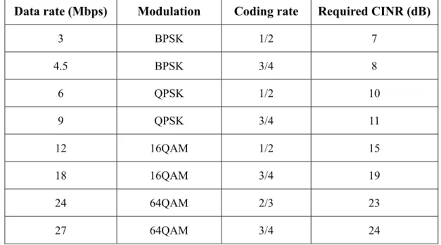
depends on the data rate. The IEEE 802.11p defines eight different data rates between 3 and 27 Mbps [8]. The data rates of 6 Mbps or higher are generally assumed for V2V communications [40]-[41]. Their required CINRs are listed in Table 2.4. Higher data rates result in shorter transmission time, but require higher CINR to successfully receive the packets.
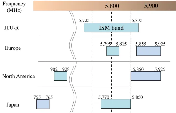
2.3 Frequency Band Allocations
The ITS frequency bands allocations in Europe, the North America and Japan are summarized in Fig. 2.4. A frequency band centered at 5.8 GHz is specified based on the ITU-R Recommendation M.1453-2 [42]. In Europe, the frequency band 5795-5815 MHz is used for road transport and traffic telematics (RTTT) applications. The frequency band 5,875-5,925 MHz is designated to ITS safety applications and the objective with the non-safety applications in the band 5,855-5,875 MHz is to provide non-safety communication services that would enhance the ITS concept for V2V and V2I communications [43]. In the North America, the frequency band 902-928 MHz is currently used for ITS services such as ETC while a shared bandwidth of 75 MHz frequency band from 5,850 to 5,925 MHz is allocated for DSRC applications in 1999.
Table 2.4: Main candidate data rates for IEEE 802.11p based V2V communications
Data rate (Mbps) Modulation Coding rate Required CINR (dB)
3 BPSK 1/2 7 4.5 BPSK 3/4 8 6 QPSK 1/2 10 9 QPSK 3/4 11 12 16QAM 1/2 15 18 16QAM 3/4 19 24 64QAM 2/3 23 27 64QAM 3/4 24
2.3 Frequency Band Allocations
19
Fig. 2.4: ITS frequency bands allocation
The 5.9 GHz band is divided into eight channels (one control channel with 10 MHz bandwidth, six service channels with 10 MHz bandwidth and one reserve channel with 5 MHz). The safety-related information is transmitted in the control channel, while the service channels are used for traffic management applications, infotainment applications, etc.
In Japan, in addition to the 5.8 GHz band which is currently used for ETC, frequency band 755-765 MHz is allocated for V2V and V2I communications. As summarized in Fig. 2.5, the frequency band centered at 760 MHz was allocated in the past for analogue television broadcasting services. It became available after the digitization of television broadcasting which was completed in April 2013. After a series of tests and road experiments, this band was officially allocated for ITS safety support applications in December 2012 [44]. Since the 760 MHz frequency band has lower propagation and diffraction losses caused by buildings and obstacles than the 5.8 GHz frequency band, the former one is suitable for communications at NLOS area, such as V2V communication at intersections. Frequency (MHz) ITU-R Europe North America Japan
5,800
5,900
5,725 5,875ISM band
5,795 5,815 5,855 5,925 5,850 5,925 902 928 755 765 5,770 5,85020
Fig. 2.5: Frequency arrangement regarding 700 MHz range in Japan
2.4 Radio Propagation Model for Intersections
Propagation over paths of length less than 1 km is affected primarily by buildings and trees, rather than by variations in ground elevation. In particular, the effect of buildings is predominant in vehicular environments, especially in urban areas. The corners at intersection are often occupied by buildings, which may block the direct path between transmitting and receiving vehicles. Under such NLOS circumstances, the received signal power may be strongly dropped. On the other hand, if the vehicles are on the same street, and the direct ray between them is unobstructed by obstacles such as buildings, the radio link is considered LOS. In this case, the received power may be much larger than the NLOS case.
Radio propagation in vehicular environments can be typically categorized into these two cases. Thus, two radio propagation models that can predict the propagation losses for wireless transmission around intersections are necessary. Moreover, both 5.8 GHz and 760 MHz are the candidate frequency bands for ITS in Japan. It would be the best that the propagation models can cover the above spectra. One of the promising candidates is ITU-R P.1411-6 [45], which provides methods for estimating path losses in urban and suburban areas over the frequency range from 300 MHz to 100 GHz. The models recommended by the International Telecommunication Unit (ITU) are widely accepted and used for coordination and comparison purpose [46]. Therefore, in this dissertation, the ITU-R P.1411-6 path loss models are employed.
Analog and digital TV
13ch 62ch470 ~ 770 MHz Analog TV Analog TV
1ch 3ch 4ch 12ch170 ~ 222 MHz
90 ~ 108 MHz
Before
Other services Digital TV
13ch 52ch470 ~ 710 MHz
90 ~ 222 MHz
After Mobile ITS
2.4 Radio Propagation Model for Intersections
21
2.4.1 Propagation Model for LOS Situation with Street Canyons
For the frequency range from 300 MHz to 3 GHz, basic transmission loss can be characterized by two slopes and a single breakpoint. An approximate lower bound is given by 𝐿LOS = 𝐿𝑏𝑝+ { 20 log10(𝑑 𝑅 𝑏𝑝 ⁄ ) for 𝑑 ≤ 𝑅𝑏𝑝 40 log10(𝑑 𝑅 𝑏𝑝 ⁄ ) for 𝑑 > 𝑅𝑏𝑝 (2.1)
where d is the distance between the transmitting and receiving vehicles. Rbp is the
breakpoint distance and is given by
𝑅𝑏𝑝≈4ℎtℎr
𝜆 (2.2)
where λ is the wavelength. ht and hr are the height of transmitting and receiving
antennas, respectively. Lbp is a value for the basic transmission loss at the break point,
defined as
𝐿𝑏𝑝 = |20 log10(𝜆2 8𝜋ℎ
tℎr
⁄ )| (2.3)
An approximate upper bound is given by
𝐿LOS = 𝐿𝑏𝑝+ 20 + { 25 log10(𝑑 𝑅 𝑏𝑝 ⁄ ) for 𝑑 ≤ 𝑅𝑏𝑝 40 log10(𝑑 𝑅 𝑏𝑝 ⁄ ) for 𝑑 > 𝑅𝑏𝑝 (2.4)
The upper bound has the fading margin of 20 dB. In addition, the coefficient before break point is set to 2.5 since that a short distance leads to weak shadowing effect.
Finally, an approximate median bound is given by
𝐿LOS = 𝐿𝑏𝑝+ 6 + { 20 log10(𝑑 𝑅 𝑏𝑝 ⁄ ) for 𝑑 ≤ 𝑅𝑏𝑝 40 log10(𝑑 𝑅 𝑏𝑝 ⁄ ) for 𝑑 > 𝑅𝑏𝑝 (2.5)
22
2.4.2 Propagation Model for NLOS with Street Canyons
This situation is depicted in Fig. 2.6. Here, we assume that the antenna heights of transmitting and receiving vehicles are below the rooftop level. The propagation loss is given as
𝐿NLOS = −10 log10(10−𝐿r⁄10+ 10−𝐿d⁄10) (2.6)
where Lr and Ld are the reflection and diffraction losses, respectively. The reflection loss
is yielded by nine purely reflections, and is defined by 𝐿r = 20 log10(𝑥1+ 𝑥2) + 𝑥1𝑥2 1 𝑤1𝑤2 3.86 𝛼3.5 + 20 log10( 4π 𝜆 ) (2.7)
where 𝛼 is the corner angle in rad, and 0.6 < 𝛼 < π. x1 and x2 are the distances from
transmitting and receiving vehicles to the intersection center, respectively. w1 and w2 are
the street widths at the position of the transmitting and receiving vehicles, respectively. These parameters are illustrated in Fig. 2.6. The diffraction loss can be calculated as
𝐿d= 10 log10[𝑥1𝑥2(𝑥1+ 𝑥2)] + 2𝐷a− 0.1 (90 − 𝛼 180 π ) + 20 log10( 4π 𝜆) (2.8) where 𝐷a = 40 2π[arctan ( 𝑥1 𝑤1 ) + arctan (𝑥2 𝑤2 ) −π 2] (2.9)
Fig. 2.6: Definition of parameters for NLOS condition
Building 𝑤1 𝑥1 Tx Rx
𝛼
3.1 Introduction
23
Chapter 3.
Relay-Assisted V2V
Communications with Payload
Combining
This chapter first proposes a packet payload combining relay (PCRL) scheme to alleviate packet congestion issue at RS for relay-assisted V2V communications (R-V2VC) scheme. In addition, a time division grouping (TDG) method is introduced to PCRL scheme in order to mitigate the effect of HT problem. Next, an analytical model is derived to theoretically analyze the packet transmission rate at RS by modeling the backoff process at RS as a Markov chain and using the signal transfer function of the generalized state transition diagram. Finally, computer simulations considering a single intersection scenario are conducted to validate the model as well as confirm the effectiveness of PCRL scheme.
3.1 Introduction
Addition of RS to CSMA/CA based V2V communications can effectively mitigate the effect of shadowing as well as compensate fading loss and thus improve the reliability of V2V communications, especially around intersection environments. The effectiveness of the R-V2VC scheme has been shown in previous works by theoretical analysis and simulations [17], [47]. However, as the number of VSs increases, the number of need-to-be transmitted packets at RS becomes larger. This poses an issue that is not obvious when traffic is very low. At high traffic conditions, it takes RS longer time to contend for its transmission. As a result, the number of awaiting packets in the transmit queue at RS increases. Since the queue size is limited and each packet has its
24
delay requirement, the packets may need to be dropped. If the packet drop happens, the R-V2VC scheme cannot improve the PDR. Therefore, the potential improvement brought by RS cannot be fully obtained as investigated in [17]. Thus, it is necessary to avoid the packet congestion at RS. Employing dual frequency bands for the R-V2VC scheme was proposed in [17], [47] to solve the congestion issue. However, frequency resources are precious and not always available in many countries.
There are many studies about the performance of CSMA/CA MAC protocol under high traffic conditions. The authors in [48] proposed an adaptive contention window mechanism, which dynamically selects the optimal back-off window according to the estimate of the number of contending stations. Another approach is dynamic optimization on range (DOOR) [49] method which was proposed to improve the whole system performance by partitioning the number of stations into many sub-ranges and calculating the optimal parameters for each sub-range. Although the proposals dynamically adjust the parameters of CSMA/CA, they don’t intend to decrease the packet drop due to congestion.
For unicast duplex communication, network coding (NC) [50]-[51] is considered as a solution to reduce air traffic by relay. The principle of NC is to mix two data at an intermediate network node and multicast it to both senders. The senders receive the encoded packets and deduce from it the messages that were originally intended to be received. Regarding vehicular safety communications (VSC) system, a retransmission scheme using NC was proposed [21] to improve the PDR of V2V communications. In the scheme, multiple native V2V packets are encoded with exclusive-or (XOR) operation and the encoded packet is used for retransmission. However, retransmission increases air traffic and is not effective when the number of VSs is large.
In this chapter, a R-V2VC scheme with payload combining relay (R-V2VC/PCRL) is proposed in order to mitigate the packet congestion at RS. An analytical model is derived to theoretically analyze the packet transmission rate at RS by modeling the backoff process at RS as a Markov chain and using the signal transfer function of the generalized state transition diagram. Moreover, a time division grouping method is introduced to the R-V2VC/PCRL scheme for mitigating the HT problem.
![Fig. 1.1: Lack of safety confirmation is the most cause of accidents [3].](https://thumb-ap.123doks.com/thumbv2/123deta/7730557.1711567/22.892.134.767.165.499/fig-lack-safety-confirmation-cause-accidents.webp)
![Fig. 1.3: Traffic accidents happen most often in urban area, especially around intersection [3]](https://thumb-ap.123doks.com/thumbv2/123deta/7730557.1711567/25.892.151.736.781.1044/fig-traffic-accidents-happen-urban-area-especially-intersection.webp)
![Fig. 3.5: An example of linear TDG with four groups [52]](https://thumb-ap.123doks.com/thumbv2/123deta/7730557.1711567/51.892.234.665.151.693/fig-example-linear-tdg-groups.webp)