Japan Advanced Institute of Science and Technology
JAIST Repository
https://dspace.jaist.ac.jp/
Title 光散乱モデルに基づく顕微鏡画像解析による眼内レン
ズの特性評価に関する研究
Author(s) KAY THWE MIN HAN Citation
Issue Date 2020‑09
Type Thesis or Dissertation Text version ETD
URL http://hdl.handle.net/10119/16996 Rights
Description Supervisor:小谷 一孔, 先端科学技術研究科, 博士
Visibility evaluation for intraocular lens with glistening by microscopic image analysis based on
light scattering model
Kay Thwe Min Han
Japan Advanced Institute of Science and Technology
Doctoral Dissertation
Visibility evaluation for intraocular lens with glistening by microscopic image analysis based on
light scattering model
Kay Thwe Min Han
Supervisor: Professor Kazunori Kotani
Graduate School of Advanced Science and Technology Japan Advanced Institute of Science and Technology
Information Science
September 2020
Abstract
Visual function is decreased due to glistening and subsurface nanoglistening (whiten- ing) after intraocular lens (IOL) implantation into human eyes. Glistening means fluid filled micro-sized vacuoles, on the other hand, whitening is nano-sized vacuoles in IOL which lead to light scattering and affect human’s vision quality. Glistening observation and light scattering in IOL mainly depend on the characteristics of glistenings which are size, shape, refractive index, and number of glistenings. Furthermore, glistening occur- rence in IOL depends on various conditions. Moreover, vision quality can also be different based on these facts. Glistening is increasingly over time and so it cannot be stopped by medicine and treatment. The best treatment for glistening is surgical removal and thus, the effect of glistening in IOL is required to study. We approach the light scattering problem from time and cost-effective way which evaluate the visibility of IOL.
Several researches studied glistenings from ophthalmology and assessed the conse- quence of glistening in vision quality by clinical tests such as contrast sensitivity, visual acuity and glare testing or wavefront measurements of the human eyes. This kind of research is required to participate by the patients and assessed light scattering in IOL by using clinical equipment such as C-Quant, spectrometer and Scheimpflug photogra- phy and thus, it is time consuming and costly to study. Moreover, these studies report the light scattering from single sphere particle but multiple particles scattering for IOL are not considered. For the real light scattering problem in IOL, light transmittance to the retina which can interfere by glistenings is not only for single particle, but also multi-glistenings. In multiple glistenings, the distance between particles are important in light scattering measurement of IOL. If the particles are brought closer together, so that their surfaces are from one another, then their scattering volumes begin to overlap.
Therefore, the total scattering volume from the two glistenings is less than the sum of the two-individual scattering volumes. When light that enters the overlap volume, light can scatter less efficiently than light that enters a part of the non-overlapping scattering.
Finally, there is no report to evaluate the visibility of IOL with glistenings to solve each of the above problems.
This research proposes optical model to study the glistenings in IOL with visibility evaluation from multiple light scattering with T-matrix method. However, this optical model considers the important facts to overcome the real problems which are not yet developed by the previous studies. When glistening numbers are grown, light scatter problem may occur inside the lens and vision quality will be degraded. Firstly, visi- bility function is evaluated based on the glistening characteristics in the optical model.
When microvacuoles are densely located in IOL, light scattering for single particle is not sufficient and multiple light scattering is important to be considered. Therefore, mul- tiple light scattering of glistenings are calculated by using T-matrix theory. Moreover, light transmission through Intraocular lens (IOL) with glistenings and whitenings are also computed. In fact, the proposed model study the characteristics of laboratory-induced glistenings under temperature changes, calculate the light scattering from multiple light scattering theory and simulate the light transmission to the retina.
Although light scattering is measured from different approaches, there is no research of light scattering effects differs depending upon the human activities. In this research, the most important approach is visibility evaluation in considered from human activities such as driving at night, studying and walking. Furthermore, this optical model evaluates visibility functions of IOL with glistenings through glare and quality of retinal image contrast. Glistenings give arise light scattering in IOL and as a result of intraocular light scatter called straylight in retina, disability glare. The quality of human vision depends on the image on the retina. Disability glare can cause the loss of retinal image contrast due to glistenings in IOL. Therefore, reduction of contrast due to glistenings are evaluated for visual functions and assessed the quality of the lens degradation. As a summary, this research combines all the important facts to model the visibility evaluation of intraocular lens with glistenings by microscopic image analysis based on light scattering model.
Key Words: Visibility Evaluation, Optical Model, Multiple Light Scatter- ing, T-matrix, Glistening
Acknowledgments
I would like to express the deepest appreciation to my advisers Professor Kazunori Kotani, Associate Professor Waree Kongprawechnon, Assistant Professor Prarinya Siri- tanawan, and former advisor from SIIT, Dr. Bunyarit Uyyanonva for the patient guid- ance, encouragement, and advice they have provided throughout my time as their student.
Without their guidance and persistent help, this dissertation would not have been possible.
I would like to thank my committee members from JAIST, Professor KANEKO Mineo, Associate Professor HASEGAWA Shinobu, and Associate Professor IKEDA Kokolo for offering their time, comments, support, and guidance on this dissertation. Moreover, I am also thankful to committee members from SIIT and NECTEC(Thailand), Profes- sor Stanislav S. Makhanov, Associate Professor Pakinee Aimmanee, and Dr.Chanjira Sinthanayothin for their thoughtful comments, recommendations, and intellectual contri- butions to this dissertation. I thank Japan Advanced Institute of Science and Technology for permission to submit the conference and journals. Furthermore, I would like to express my appreciation to Dr.Nattapon Wongcumchang, Dr.April Cho Aung, Dr.Zwe Zaw Zaw Naing, Dr.Aye Min Thant, and Dr. LaWun Phyu Phyu, medical doctors for providing me Intraocular lens(IOL) and knowledge of glistening formation in IOL. I also would like to extend my appreciation to Gunter, P’Chat, and Bell for the knowledge of microscope and microscopic images.
I would like to thank, SIIT-JAIST dual degree program, Sirindhorn International Insti- tute of Technology (SIIT), Japan Advanced Institute of Science and Technology (JAIST), and National Electronics and Computer Technology Center (NECTEC) for providing me this opportunity and supporting me financially. I am thankful to my Myanmar, Thai, Japanese, and other international friends from SIIT and JAIST who assisted me in iden- tifying relevant on living abroad and guided me throughout my work including coding, presenting, and report writing. Finally, my deep and sincere gratitude to my family for their continuous and unparalleled love, help, and support. I am forever indebted to my parents for giving me these opportunities and experiences that have made me who I am.
Last but not least, I am forever thankful to my best friend, Mya Thandar for giving me a lot of encouragement, support, and continuous optimism to complete this dissertation.
This journey would not have been possible if not for them, and I dedicate this milestone to them.
Contents
Abstract i
Acknowledgments iii
1 Introduction 1
1.1 Overview of Visibility evaluation for intraocular lens with glistening based
on light scattering model . . . 1
1.2 Research Problem and Motivations . . . 3
1.3 Research Vision, Purpose and Objectives . . . 4
1.4 Dissertation Scope and Outline . . . 5
2 Related Works 7 2.1 Clinical studies . . . 7
2.2 Mathematical studies . . . 10
3 Glistening in Intraocular Lens 12 3.1 Anatomy of the human eyes . . . 12
3.2 IOL implantation . . . 12
3.3 Scatter in IOL . . . 13
3.4 Electromagnetic Scattering . . . 15
3.5 Measurement of Visibility . . . 16
3.5.1 Visual Acuity . . . 16
3.5.2 Contrast Sensitivity . . . 18
3.5.3 Disability glare . . . 19
3.6 Characteristics of glistenings . . . 19
3.7 Glistening generation . . . 20
4 Image Analysis for glistenings in IOL 23 4.1 Microscopic Images of IOL . . . 24
4.1.1 Glistening and Whitening in IOL images . . . 24
4.2 Background Subtraction . . . 27
4.3 Thersholding . . . 28
4.4 Fill Holes . . . 29
4.5 Separation of Overlapping objects . . . 30
4.6 Glistening counting . . . 31
4.7 Glistening measurements . . . 32
4.8 Result of Image Analysis . . . 32
4.8.1 Diameter of glistening . . . 32
4.8.2 Number and density of glistening . . . 33
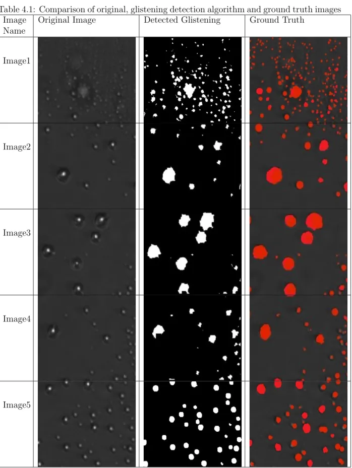
4.9 Accuracy of Glistenings . . . 33
5 Light Scatter Measurement 36 5.1 Application of T-Matrix approach to light scatter calculation . . . 36
5.2 Light Transmission by Power Flux . . . 39
5.3 Result of CELES Simulation . . . 39
5.3.1 Simulation of Total Electric Field . . . 40
5.3.2 Power Transmission and Loss . . . 42
6 Visibility Evaluation of Intraocular Lens 45 6.1 Retinal Illuminance(E) from the glare source . . . 45
6.2 Glare and contrast sensitivity . . . 50
7 Conclusion and Future Work 53 Publications 56 Bibliography 57 A Minor Research : Simulation of Multiple Light Scattering in Intraocular lens with glistenings by T-Matrix 63 A.1 Introduction . . . 63
A.1.1 Purpose of study . . . 63
A.1.2 Scope of study . . . 64
A.2 Literature review . . . 65
A.2.1 Grade of glistenings . . . 65
A.2.2 Problem statements . . . 65
A.3 Methodology . . . 67
A.3.1 Scattering Parameter . . . 67
A.3.2 T-Matrix . . . 67
A.4 Simulation . . . 70
A.5 Discussion . . . 72
A.6 Appendix . . . 72
A.6.1 Spherical Vector Wave . . . 72
A.6.2 Spherical Bessel Function and Hankel Function . . . 72
References 74
This dissertation was prepared according to the curriculum for the Collaborative Ed- ucation Program organized by Japan Advanced Institute of Science and Technology and Thammasat University.
List of Figures
1.1 Basic concept of research . . . 2
1.2 Block Diagram of Visibility evaluation for intraocular lens with glistenings by microscopic image analysis based on light scattering model . . . 6
2.1 Scheimplfug camera to measure back-scattering [22] . . . 8
2.2 Light transmittance measurement with spectrophotmeter [23] . . . 8
2.3 C-Quant device to measure light scattering [24] . . . 9
3.1 Anatomy of the human eyes with cataract [31] . . . 14
3.2 Scattering in human eyes [32] . . . 14
3.3 The difference between Mie scattering and Rayleigh scattering [34] . . . 16
3.4 Snellen chart for visual acuity testing [36] . . . 17
3.5 Trumbling E chart for visual acuity testing [37] . . . 18
3.6 Pelli Robson chart for contrast sensitivity testing [38] . . . 19
3.7 Hydrophilic acrylic IOL[43] . . . 21
3.8 Induction of IOL to generate microvacuoles . . . 22
4.1 Flow chart of Image Analysis . . . 23
4.2 Lens imaging with microscope . . . 24
4.3 Glistening in microscopic image of IOL with 20X magnification . . . 25
4.4 Glistening in microscopic image of IOL with 20X magnification . . . 25
4.5 Glistening in microscopic image of IOL with 40X magnification . . . 26
4.6 Glistening in microscopic image of IOL with 60X magnification . . . 26
4.7 Schematic diagram of background subtraction by rolling ball method [47] . 27 4.8 Background subtraction in microscopic image of IOL . . . 28
4.9 Thresholding in microscopic image of IOL . . . 29
4.10 Filling holes in microscopic image of IOL . . . 30
4.11 Overlapping parts are separated by watershed algorithm . . . 31
4.12 Glistening counting in microscopic image of IOL . . . 31
4.13 number and diameter of glistening from IOL image analysis . . . 32
4.14 glistenings are defined by zone . . . 33
5.1 Block Diagram of Transition matrix in one particle and between two parti- cles in which scattering field coefficients are calculated from incident field coefficients . . . 38
5.2 Simulation of light scattering by CELES . . . 40 5.3 Position of Grade 1 glistenings and total electric field after light scattering 41 5.4 Position of Grade 2 glistenings and total electric field after light scattering 41 5.5 Position of Grade 3 glistenings and total electric field after light scattering 42
5.6 Position of Grade 4 glistenings and total electric field after light scattering 42
5.7 Power Transmission of IOL for glistening . . . 43
5.8 Power Loss of IOL for glistening . . . 43
5.9 Power Transmission of IOL for whitening . . . 44
5.10 Power Loss of IOL for whitening . . . 44
6.1 Light Transmission through IOL and focus on retina[65] . . . 47
6.2 Varing of veiling luminance according to incident glare source for grade 2 glistening . . . 48
6.3 Varing of veiling luminance according to incident glare source for grade 3 glistening . . . 48
6.4 Varing of veiling luminance according to incident glare source for grade 4 glistening . . . 49
6.5 Disability Glare by Different Grade of Glistenings at visual angles 15◦ and 30◦ . . . 49
6.6 Reduction of Image Contrast by glare at Billboard’s central point . . . 51
6.7 Reduction of Image Contrast by glare at Billboard’s surroundings . . . 51
6.8 Reduction of Image Contrast by glare at Horizon of billboard . . . 51
6.9 Reduction of Image Contrast by glare at Road Surface . . . 52
A.1 Glistening formation inside intraocular lens . . . 64
A.2 Different grades of glistenings in IOL depending upon the number of for- mations . . . 66
A.3 Block Diagram of Transition matrix in one particle and between two parti- cles in which scattering field coefficients are calculated from incident field coefficients . . . 69 A.4 Position of Grade 1 glistenings and total electric field after light scattering 71 A.5 Position of Grade 2 glistenings and total electric field after light scattering 71 A.6 Position of Grade 3 glistenings and total electric field after light scattering 71 A.7 Position of Grade 4 glistenings and total electric field after light scattering 72
List of Tables
3.1 Description of IOL . . . 21 4.1 Comparison of original, glistening detection algorithm and ground truth
images . . . 35 6.1 Spectral Luminous Efficiency Functions [64] . . . 46 6.2 Luminance from different scenes [66] . . . 50
Chapter 1 Introduction
1.1 Overview of Visibility evaluation for intraocu- lar lens with glistening based on light scattering model
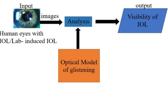
Intraocular lens (IOL) is a lens which is implanted in human eyes to replace natural cloudy lens during cataract surgery. Degraded vision quality is related to the formation of glistening in IOL. Glistening is defined as microvacuoles inside the IOL optic when light passes through it. In fact, glistenings can be seen in all IOL materials but are mostly found with hydrophobic acrylic IOLs[1][2][3]. From the previous clinical study, glistening was found in 57% of IOL from 2 to 16 months after IOL implantation[4]. When IOL is implanted into human eyes, the temperature differences between the human body and the manufacturing process occur water gap inside the lens. There are many research studied glistenings from ophthalmology and assessed the consequence of glistening in vision quality by clinical tests such as contrast sensitivity, visual acuity, and glare testing or wavefront measurements of the human eyes. These studies required to participate by the patients and calculated light scattering manually and furthermore, it is time-consuming and costly to research. However, this research approach optical modeling in which visibility function is evaluated from glistening characteristics, human activities, and light scatter condition IOL. For this purpose, the input is IOL images with glistenings from human eyes, analyze these glistenings in IOL by image analysis, and develop an optical model to cope visibility evaluation of IOL. Figure 1.1 shows the fundamental steps of this research.
Figure 1.1: Basic concept of research
When light traverses into the human eye, it is refracted by cornea and lens to produce an image on the retina. In human eyes, the retina is the light-sensitive part of the eye in which fovea is located at a central region for high acuity of vision. Moreover, the cell structure of the retina is composed of rod and cone cells to be light-sensitive and the function of rod and cone cells are applied based on human activities such as driving at night time or studying at day time. However, rod cells are more light-sensitive than cone cells because these cells can be sensitive for the entire visible spectrum. Therefore, the wavelength of the light which passes through the lens to the retina is considered to be in the range of the human visible spectrum of rod and cones.
In general, glistenings can increase the intraocular stray light[5]. However, the stray light which impacts vision quality on the retina is associated with forward light scatter.
Forward scattering means that light scattered towards the retina (angle between 0º and 180º), and can cause veiling illuminance on the retinal image which affects the reduction in contrast. In addition, light scattering may produce halos or glare due to the increas- ing of diffused light on the retina. However, the amount of intraocular stray light that can affect the vision quality depends on the characteristics of glistenings such as size, shape, refractive index, and the number of the glistening. According to previous studies, glistenings has been reported with the diameter range from 10 to 20µm by Dogru et al.
(2000) [6]. In addition, the different size of glistenings have been found by DeHoog et al. (2014) from 2 to 200µm [7]. Henriksen et al (2015) separate the size of glistenings into two groups: 6 to 25µm or greater than 25µm [8]. Recently, the size of glistening is significantly varied and observed by Takahashi et al. (2015) with three different sizes:
100 nm, 150 nm, and 200 nm[9].
Next, the number of glistening in IOL is also an important factor for grading of glis- tening. Traditionally, glistenings are graded in the intraocular lens by clinicians through the slit lamp. They manually counted the number of glistenings and report as different grades. Therefore, several studies described grading by the number of glistenings present in IOL. Firstly, three grades of glistenings such as 1 +,2 +, and 3 + have been reported by Dhaliwal et al. (1996) [10]. Moreover, glistening grades are recorded as 0 to 3+ by Wilkins and Olson (2001)[11]. They denote 0 for no glistenings, 1+ for less than 10, 2+ for 10 to 50, and 3+ for more than 50. Yet, Cisneros-Lanuza et al.(2016) proposed
to grade 1+ for 10 to 20, 2+ for 20 to 30, 3+ for 30 to 40 and 4+ for more than 40 glistenings[12] .Glistening number are classified and measured per mm2 by Weindler et al. (2019) where grade 0 (none), grade 1 (1-100), grade 2 (101-200), grade 3 (201-500) and grade 4 (more than 500) [13]. According to previous studies, grading scales can be represented by the occurrence of glistening numbers in IOL, but a common agreement is not found on defining glistening’s grading.
Glistenings can be seen in IOL because of the different refractive indices between the IOL material and water inside the IOL material. However, refractive index values are varied due to the material and type of IOL. For example, PMMA (1.49), silicone (1.43-1.46), hydrophilic acrylic (1.47), hydrophobic acrylic (1.47 to 1.55). Impact of light scattering caused from glistenings’ IOL has been studied in [8][14][7][12]. The previous research [8][14][15] evaluated light scattering in IOL by using medical equipment such as straylight meter (C Quant log) and Scheimpflug photography. Nevertheless, other research analyzed from mathematically modeling with Mie scattering theory [7][16]. If particle shapes are sphere, Mie theory is more appropriate to solve the light scattering problem. Since the different shapes of glistenings have been found in IOL, multiple light scattering occurs. The single light scattering problem by a sphere is not sufficient to satisfy the problem.
Several studies report the light scattering from one sphere. Multiple scattering for IOL has not considered. In this research, T-Matrix method is applied for light scattering in IOL images by mathematical modeling and optical simulation to evaluate the visibility of IOL. In fact, T-matrix method calculated a pair of spherical particles as a single scatterer and has originally been developed by Waterman[17]. The proposed methodology aims to simulate multiple scattering in IOL, although many research used Mie scattering theory to model a single glistening. As a result, multiple light scattering of the electric field through glistenings in IOL can be calculated and simulated. Moreover, visual functions is evaluated from different light conditions and human activities. In this research, all of these important facts are combined as an optical model of IOL with glistenings and evaluate the visibility of human eyes with IOL.
1.2 Research Problem and Motivations
The visual functions that are complained after implantation is small bright particle forma- tions called glistenings in IOL which is associated with light scattering. Since glistenings are possibly in any material and design of IOL, light scattering can be encountered by the patients after the following years of the IOL implantation [1][4][14]. When the inci- dent light passes through a medium called an intraocular lens, light can be transmitted, reflected, and scattered to random directions due to glistenings. However, the previous studies[18] show that the direction of light scattering which is caused by glistening prop- agates backward and forward. Forward scattering increase the intraocular straylight and backward scattering decrease in light transmittance to the retina. Therefore, image qual- ity which is received by the retina is correlated to light scattering in IOL and transmission to retina. Moreover, a light scattering of IOLs is associated with unwanted glare, opti- cal defects, unclear image quality, and other phenomena that can affect daily activities.
Hence, visibility evaluation is required from IOL with glistenings in which light scattering occurred inside the lens.
To assess light scattering in IOL, clinical studies used different types of equipment such as C-Quant, spectrometer, and Scheimpflug photography. This kind of research is costly and clinicians are also required to collaborate. Moreover, these research have the following drawbacks.
• Scheimpflug device did not provide images of required resolution to perform auto- mated counting of separate glistenings[19].
• Glistenings less than 2µm in diameter cannot be detected smaller sizes with slit-lamp photographs[8].
• C-Quant instrument delivers the straylight parameter of the eye for a fixed visual angle. This might appear as a limitation as one may wonder about the straylight value at smaller or larger angular distances of the glare source[20].
• Glistening particles are aggregated based on the grade and shapes are also different.
Light scattering in glistenings are calculated based on single particle scattering theory and near-field scattering effects are not considered.
Therefore, we approach the light scattering problem from time and cost-effective way which evaluates the visibility of IOL. Several research studied the quality of vision from a clinical assessment such as contrast sensitivity and visual acuity but the lifetime of the lens from affected glistenings is not reported. Moreover, these studies report the light scattering from a single sphere particle and multiple particle scattering for IOL are not considered. For the real light scattering problem in IOL, light transmittance to the retina which can interfere by glistenings is not only for a single particle, but also multi- glistenings are counted to evaluate visual quality. If the glistening particles are far from one another then each particle scatters light as if the other particle was not there, and the total light-scattering is simply twice the scattering of an individual particle. However, if the particles are brought closer together so that their surfaces are from one another, then their scattering volumes begin to overlap. Therefore, the total scattering volume from the two glistenings is less than the sum of the two-individual scattering volumes. When the light that enters the overlap volume, light can scatter less efficiently than light that enters a part of the non-overlapping scattering. Therefore, light scattering for group glistening is another problem statement for our research and we follow the above process as single glistening scattering in IOL. Finally, there is no report to evaluate the visibility of IOL with glistenings to solve each of the above problems.
1.3 Research Vision, Purpose and Objectives
The purpose of this study is to evaluate the visibility function of IOL with glistenings from the optical model. In this research, the proposed model study the characteristics of glistenings which are from the lab under temperature changes, calculate the light scatter- ing from multiple light scattering theory and simulate the light transmission to the retina.
Moreover, the most important approach of this research considers visual function evalua- tion from human activities such as driving at night, studying, and walking. Although light scattering is measured from different approaches, there is no research of light scattering effects differs depending upon the human activities. Therefore, this research proposed
the optical model which is intended to evaluate the visibility of intraocular lens with the glistening but cost-effective and accurate methods are also applied for light scattering.
1.4 Dissertation Scope and Outline
The scope of this research is lied on small reflections of light by glistenings that cause for- ward light scattering in IOL. Glare is the result of forward light scattering and interferes in daily activities of humans. There are several research from clinical studies that inves- tigate the correlation between glistenings and forward light scatter problems. However, there are no findings that visual functions such as disability glare, human activities, and light scattering conditions which can affect the vision quality of human.
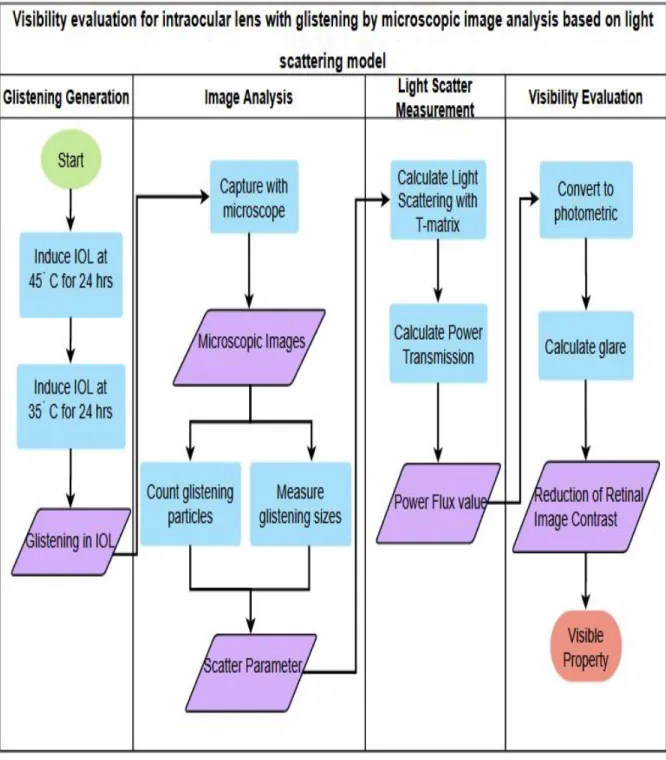
In this research, we develop the optical model for the visibility evaluation of IOL from multiple light scattering T-matrix methods. However, this optical model considers the important facts to overcome the real problems which are not yet developed by the previous studies. For this purpose, the flow of this dissertation is outlined as the following Figure 1.2 and each title of the columns is explained briefly.
• Basically, this research is conducted from information science point of view com- bining with optics to simulate how electric fields are scattered according to the properties of glistenings. Therefore, glistening characteristics are important pa- rameters to calculate the total electric field. Many research reports that glistening can be different size, numbers, shapes, and refractive index which can affect light scattering. Since IOL images from patients have limited resolution to identify the characteristics of glistenings and thus, glistenings are generated in the laboratory with different temperature setting as human body temperature changes. The details are explained in section 3.7.
• Image analysis can help to identify glistening characteristics in IOL and captured with a microscope. From this step, properties of glistenings are received to calculate the light scattering of IOL for the next step in chapter 4.
• Light transmission through IOL to the retina is calculated from electromagnetic light scattering theory and described in chapter 5.
• Visual function is evaluated with one problem of glistenings called glare. For this purpose, straylight value is calculated and evaluated lens quality as chapter 6.
Figure 1.2: Block Diagram of Visibility evaluation for intraocular lens with glistenings by microscopic image analysis based on light scattering model
Chapter 2
Related Works
Today’s cataract surgery implant an intraocular lens (IOL) in the capsular bag inside the eyes. There are different types of IOLs that can be used during cataract surgery for different purposes, such as monofocal, multifocal, accommodating, and toric designs.
Moreover, various IOL material and designs can be available today, such as hydrophobic acrylic, hydrophilic acrylic, silicone, and polymethylmethacrylate materials; aspheric and nonaspheric, anterior chamber and posterior chamber, one-piece or three-piece, and in-the- bag or sulcus-fixated designs. However, temperature changes between the human body and the manufacturing process cause glistening which accumulates fluid as microvacuoles in IOL. These glistenings are visible through slit-lamp examination since the refractive index difference between that of microvacuoles and IOL materials makes the optical effect.
As a result, the differences in refractive indices cause redirection of light and light scat- tering. Since this research aims to evaluate the vision quality from IOL with glistening, this chapter will firstly discuss available methods to assess the aspects of quality of vi- sion. Many clinical reports investigated the impact of glistenings in intraocular lenses on visual functions such as contrast sensitivity (CS) and visual acuity (VA). However, these findings reported no common descriptions for the effect of glistenings on measured visual quality. Moreover, the study of light scattering in IOL with glistenings can be found in two different methods: Clinical Studies and Mathematical studies. In clinical method, methods of measuring can be subdivided into two categories: the optical in vitro and the optical in vivo in which the former refers to work in a whole living organism, and the latter means performing outside of a living organism.
2.1 Clinical studies
Clinical studies mean that glistenings are observed by using clinical equipment to measure light scattering and evaluate visual function from vivo or vitro methods. The first research is combined of vivo and vitro study because Werner et.al (2016) evaluated forward light scattering and straylight in hydrophobic acrylic IOL which is removed from cadaver eyes.
The significance of this research, subsurface nanoglistening is also basically considered and evaluated the impact on optical quality by using a scatterometer to measure forward light scattering and straylight values at different angles were calculated. Furthermore, a scheimpflug camera is used to measure back-scatter and the light transmittance with a spectrophotometer(Lambda 35 UV-VIS) to confirm validate the result. The following Figure 2.1 and Figure 2.2 are scheimpflug camera and spectrophotometer(Lambda 35
UV-VIS) to light scattering in IOL. However, the result concluded that straylight in hydrophobic IOLs from subsurface nanoglistenings would not affect on visual impairments.
[21]
Figure 2.1: Scheimplfug camera to measure back-scattering [22]
Figure 2.2: Light transmittance measurement with spectrophotmeter [23]
Secondly, Mo¨nestam et.al (2011) researched with vivo method by studying from pa- tients who had cataract surgery 10 years previously. This research has cooperated with 103 patients who had phacoemulsification with implantation of Acrysof MA60BM IOLs.
The purpose is to investigate the impact on visual function from light scattering and glistenings in intraocular lenses from the patients who had experienced with the specified period on eyes. At first, patients were evaluated with best-corrected visual acuity (VA),
and low contrast visual acuity (LCVA). For the purpose of light scattering measurement from IOL, Scheimpflug photography was applied and the degree of glistenings is also de- fined with slit-lamp. From this research, patients who operated 10 years previously had severe glistenings and a high level of light scattering from their intraocular lenses.[14]
The next vivo clinical research is from Bradley et.al (2015) and investigated intraocular glistenings that have an impact on light scatter and visual function depending on glistening size. This research studied in Pseudophakic patients with visual acuity no worse than 0.02 logMAR and no ocular pathology. Formerly, all IOLs were photographed, and glistenings were analyzed for size and density. Then, the measurement for logMAR corrected distance visual acuity (CDVA), mesopic 10% contrast logMAR CDVA with and without glare is performed, and straylight are assessed by a straylight meter(C Quant log). Figure 2.3 shows the C-Quant device to measure light scattering. To summarize, this research concluded with the age of the IOL which can affect on the glistening size and visual parameters.
Figure 2.3: C-Quant device to measure light scattering [24]
Next, Labus et.al (2016) observed light scattering for glistenings from vitro study.
Firstly, glistenings were generated in 7 Acrysof IOLs in the laboratory by changing dif- ferent temperatures from 37°C to 60°C in a balanced salt solution and cooled to room temperature. The objective of this research is to assess light scattering from intraocular lenses (IOLs) and create a model for predicting glistening effects on straylight. Then, the glistenings were analyzed with a microscope. Therefore, light scattering from the IOLs was experimented and assessed by using a straylight meter (C-Quant) with different scat- ter angles such as a 2.5-degree and 7.0-degree scatter angle. Then, a model in which the correlation between straylight increase and the total number and area of glistenings was proposed. But, this research is combined the mathematical method and clinical method because results were compared to the Mie theory.[12]
As the last vitro research, Weindler et.al(2019) observed the effect of glistenings on the optical quality of a hydrophobic acrylic intraocular lens. However, this research also used laboratory-induced glistening and experimented to study light scattering. Basically,
image analysis of light-microscopy photographs is applied to learn the number and size of glistenings. In addition, grades are also identified from image analysis which is based on glistening number per mm2. Grade 0 to 4 are reported such as grade 0 (none), grade 1 (1-100), grade 2 (101-200), grade 3 (201-500) and grade 4 (more than 500). For the purpose of evaluating the impact of glistenings on image quality, an optical bench test was employed to measure each IOL’s modulation transfer function (MTF) and Strehl ratio.
As a result, the number of glistenings(below grade 3) had no effect on the image quality.
However, image quality degrading in the MTF and the Strehl ratio were observed in grade 4 but there is no significant effect which can disturb the visual quality.[13]
Summary
All the research which is described from the above reports the results according to their main purposes, but there is some deficiency from clinical studies. As a summary, light scattering from glistenings has been assessed in vivo using Scheimpflug photography for backward scattering or C-Quant straylight meter (Oculus Optikgera te GmbH, Wetzlar, Germany) for forward scattering [25][26]. Although those studies showed the result, some of the research conditions are created to achieve the research goal. For example, glisten- ings that had developed naturally in the human eye and measured in a laboratory setting have shown strong scattering effects[27][28]. This research combined vivo experiments into vitro settings. Moreover, straylight measurement from vitro–induced glistenings was assessed with a modified straylight meter. Despite that study demonstrated the rela- tionship between a straylight and the number of glistenings, scattering effects will differ between various materials of IOLs. Therefore, clinical research must consider human con- ditions after implantation even though the experiments are based on vitro methods. IOL materials can produce different scattering effects and thus, those equipment are required to test for all human conditions with different IOL types. In our research, we evaluate the visibility of IOL from the disability glare which is caused by glistenings. An intraocular lens with a large number of glistenings causes disability glare at night and when looking towards the light in the daytime. Such an affected lens may also interfere with a per- son’s ability to drive safely at night. Therefore, the clinical studies are still needed some improvements to satisfy human implanted conditions and glare measurements.
2.2 Mathematical studies
Many research is not found in light scattering problems from mathematical studies. Math- ematical studies mean that the effect of glistenings in IOL is studied from light scattering theories and applied with different simulation software. The first research of mathemat- ical study use ray tracing software in an eye model. The purpose of this research is to evaluate the impact of light scatter from glistenings in pseudophakic eyes and thus, mathematical modeling and simulation are operated. As a first step, the pseudophakic eye model was constructed in Zemax using the Arizona eye model as the basis. Then, Mie scattering theory was applied to calculate the intensity and direction of light scatter- ing for spherical-shaped glistening in an intraocular lens. Additionally, the modeling and evaluation of light scattering were observed and modulation transfer function (MTF) was performed for different glistenings with various sizes and density under scotopic, mesopic,
and photopic conditions. As a result of the simulation, increasing the density of glistenings shows the significant drop in the MTF of the IOL and the pseudophakic eye.[7]
In Mooren’s research[16], laboratory-induced glistenings were generated first and then the light scatter contribution induced by microvacuoles was measured as a function of both angle and extinction and was verified by calculations using Mie theory. For this reason, four IOL types are used to measure the microvacuole particle size distribution and particle volume density by using confocal light microscopy and dark field microscopy, and the corresponding extinction coefficient γ was determined. The final output of this research summarized as IOLs with significant glistenings shows stray light levels higher than that of a healthy 20-years-old crystalline lens.
Next, this research studied for the specific size glistenings called subsurface nano glis- tenings which have described 3 sizes in experiments such as 100 nm, 150 nm, and 200 nm. Since the object of this study is to determine whether subsurface nanoglistening in hydrophobic acrylic intraocular lenses (IOL) decline visual performance. Therefore, the effect of subsurface nanoglistenings was simulated using optical design software Light- tools and Code V with the Liou-Brenann model eye and an acrylic IOL. As a result, subsurface nanoglistenings increased forward scattering slightly and reduced irradiance but significantly diminished retinal image. The effect of subsurface nanoglistenings on visual function in the absence of severe retinal disease was minimal.
Summary
The above mathematical studies are based on lab-induced microvacuoles and applied mathematical theories to evaluate the light scattering problem. Mie light scattering model is used and the results are simulated by commercial tools such as Zemax, Lighhtools, and CodeV. However, light scattering from glistenings in IOL is not calculated from the multiple light scattering approach since glistenings are densely located in IOL. Although eye-models and lab-induced glistenings have experimented from these studies, human activities are not considered for assigning wavelengths in light scattering evaluations such as night time driving or studying. In fact, human eyes have photoreceptors called rod and cones which are providing the vision to the eyes. However, rods provide vision during dim light or night also known as scotopic vision, whereas cones provide vision during day time or at bright light also known as photopic vision. Depending upon the activities of humans, light levels are different. Moreover, rod and cone cells have sensitive wavelengths.
For example, the rod is sensitive at 498 nm and is insensitive to wavelengths higher than 640 nm. In cone cells, the wavelength of approximately 420 nm, 534 nm, and 563 nm and the sensitivity may raise to provide vision over the visible spectrum [29]. However, these lighting conditions and wavelengths are not considered in the above literature.
Chapter 3
Glistening in Intraocular Lens
3.1 Anatomy of the human eyes
Human eyes are the main sense organ capable of receiving visual images, which are then carried to the brain.[30]. The eye has many functions to produce a clear vision.
• The sclera, white part of the eye and outer layer which protects the eyeball.
• The pupil, black dot at the center of the eye, and light can enter the eye through it.
• The iris, coloured part of the eye, surrounds the pupil. The main task of the iris is to control the light which enters the eye by changing the size of the pupil.
• The cornea, a clear window at the front of the eye, covers the iris and the pupil.
• A clear lens, located behind the pupil, acts like a camera lens by focusing light onto the retina at the back of the eye.
• The retina is a light-sensitive inner lining at the back of the eye. Ten different layers of cells work together in the retina to detect light and turn it into electrical impulses.
Anatomy of the eye is important to understand where cataract occurs and how and when the surgery is required to implant IOL where glistenings have been found. In Figure 3.1, Anatomy of the human eyes with cataracts can be seen when light passes through the lens. Clouded vision can be caused by cataracts and can interfere in daily activities such as driving and reading. Although several reasons for eye conditions can cause cataract, aging or injury changes the tissue in the lens of the eyes can develop the cataract more than others. Therefore, the common treatment to cataract is the surgical removal of the lens and implanted with IOL. In the next section, IOL implantation is described.
3.2 IOL implantation
The human eye has a lens that focuses light onto the retina and then sends it to the brain. Therefore, the lens is a key refractive element of the eye to see images of the visual world onto the retina. But cataract makes the lens to be cloudy and look blurry. Hence, cataract surgery removes the cloudy lens and replaces with IOL to correct vision problems.
In cataract surgery, the lens inside the eye that has become cloudy is removed and replaced
with an artificial lens (called an intraocular lens, or IOL) to restore clear vision. In fact, the intraocular lens (or IOL) is an artificial lens for the eye and helps light to enter after the natural lens is removed in cataract surgery. However, there are different types of IOL materials which can select from plastic, silicone, or acrylic. Moreover, they are available in a variety of focusing power: monofocals, aspheric, multifocal, accommodating, and toric.
• Monofocal IOL: This is the most common type of IOL which is used to remove the eye’s natural lens after cataract surgery. This type of IOL can stretch or bend to help the eye focus. But, this IOL focus at one fixed distance for close, medium, or distance vision. Basically, patients are set this type of IOL for clear distance vision but, eyeglasses are still required for reading or close work.
• Multifocal IOL: This lens is similar to the function of glasses with bifocal lenses which can help to see near and far. Moreover, this IOL provides several different focusing distances within the same lens, but it is appropriate for the patients who implant in both of the eyes rather than just one.
• Accommodating IOL: This IOL is flexible and works as a natural lens and focuses can be more than one distance. In fact, the shape of the lens is not changed, but the ciliary muscle in which IOL is accommodated can move back or forth to change the focal point for different distances.
• Toric IOL: Toric IOLs are used to correct astigmatism which is a common vision problem before and after cataract surgery. Astigmatism means that the curvature of the cornea is irregular and causes light to focus at multiple points in the eye instead of focusing only at one point on the retina and vision can be blurry. This lens helps to lessen astigmatism and thus glasses are not needed to wear after surgery.
3.3 Scatter in IOL
The degrading of vision quality by glistenings in IOL related to increased forward light and results in retinal straylight. Figure 3.2 shows how light is scattered inside the eyes.
In addition, retinal straylight is correlated to other vision complaints such as glare, halos, color, and contrast loss. Scatter in the IOL can be categorized into two types which are based on the direction of the scattering: forward scattering and backward scattering.
• Forward scatter is defined as the total amount of light scattered towards the retina (angular distribution between 0º and 180º), resulting in a veiling illuminance su- perimposed upon the retinal image and causing a reduction in contrast.[18] This situation leads to a variety of complaints, such as glare. In a clinical experiment, forward light scattering is measured by using a double-pass imaging technique or with a straylight meter.
• Backward scatter on the other hand is defined as the total amount of light scattered back towards the anterior chamber (angular distribution between 180ºand 360º), re- ducing the amount of light reaching the retina. Clinically, backward light scattering can be studied by slit-lamp examination or the use of a Scheimpflug camera.
Figure 3.1: Anatomy of the human eyes with cataract [31]
Figure 3.2: Scattering in human eyes [32]
3.4 Electromagnetic Scattering
Light scattering can be defined as the redirection of light in which an electromagnetic (EM) wave (i.e. an incident light ray) encounters an obstacle such as the glistening particle in this research. When the EM wave interacts with the discrete particle, the electron orbits within the particle’s constituent molecules are perturbed periodically with the same frequency as the electric field of the incident wave. The oscillation or perturbation of the electron cloud results in a periodic separation of charge within the molecule, which is called an induced dipole moment. The oscillating induced dipole moment is manifest as a source of EM radiation, thereby resulting in scattered light. The majority of light scattered by the particle is emitted at the identical frequency of the incident light, a process referred to as elastic scattering. In summary, the above phenomenon describe the process of light scattering as a complex interaction between the incident EM wave and the molecular/atomic structure of the scattering object; hence light scattering is not simply a matter of incident photons or EM waves “bouncing” off the surface of an encountered object.
Formal light scattering theory may be categorized in terms of two theoretical frame- works. One is the theory of Rayleigh scattering (after Lord Rayleigh) that is, strictly speaking as originally formulated, applicable to small, dielectric (non-absorbing), spherical particles. The second is the theory of Mie scattering (after Gustav Mie) that encompasses the general spherical scattering solution (absorbing or non-absorbing) without a partic- ular bound on particle size. Accordingly, Mie scattering theory has no size limitations and converges to the limit of geometric optics for large particles. Mie theory, therefore, may be used for describing most spherical particle scattering systems, including Rayleigh scattering. However, Rayleigh scattering theory is generally preferred if applicable, due to the complexity of the Mie scattering formulation. In this research, glistening particles are assumed as spheres and thus, mie scattering is relevant to apply but multiple scattering problem is also considered. The difference between Mie scattering and Rayleigh scattering can be seen in Figure 3.3. Therefore, T-Matrix approach is suitable for this research and discusses the theory in Chapter 5.
Theory of Rayleigh light scattering
This theory was initiated by Lord Rayleigh from the research on scattering from small particles and is applicable to small, spherical particles. However, Rayleigh scattering is more effective at short wavelengths. For light scatter measurement, forward scatter equals backward scatter in Rayleigh theory.
Theory of Mie light scattering
Mie scattering has no particle size definition and moreover, this type of scattering is not depend on the wavelength and forward scatter does not equal back scatter. In human eyes, normal eyes or cataract-eyes, scattering is not wavelength dependent, and thus Mie scattering is more convenient to calculate glare[33].
Figure 3.3: The difference between Mie scattering and Rayleigh scattering [34]
3.5 Measurement of Visibility
Vision is composed of many visual functions and thus, quality of vision and perceived reading ability in patients is important to be tested and measured. Vision can be mea- sured by many different tests which are used in clinics or hospitals. Generally, visual impairments in cataract are caused by intraocular forward light scatter[35] and likewise, in glistenings. However, the common visual function tests that are performed for assess- ing the visual function of cataract patients: visual acuity(VA), contrast sensitivity (CS), and glare disability (GD). Therefore, visual functions for glistenings are also assessed by these three tests. Although visual acuity (VA) is the conventional test of visual function in patients with cataracts, some good VA patients complain of poor vision. Hence, other tests of visual function such as contrast sensitivity (CS) are also evaluated to assess the quality of vision and the following sections will discuss the details of each of the tests.
3.5.1 Visual Acuity
Visual acuity (VA) is a measure of the ability of the eye to distinguish shapes and the details of objects from a specific distance. The result of Visual acuity value is described by a fraction (for example, 20/20). Visual acuity 20/20 vision is normal, otherwise, corrective eyeglasses, contact lenses, or surgery are needed to have a clear vision. In fact, visual acuity is tested monocularly with high contrast which means black letters are written on a white back. However, the patient’s eyes are tested one at a time while the other eye is covered. For this purpose, doctors use a standard chart or a viewing device with smaller letters. There are two common tests which is used in VA: (1) Snellen and (2)Trumbling E.
Snellen
The Snellen test uses a chart of letters or symbols which are arranged in different sizes by rows and columns. Viewed from specific distance away(for example, 14 or 20m), the test examine how patients can distinguish the letters by reading out to the doctor while one eye is covered. This process will repeat and read smaller and smaller letters until patients can no longer accurately distinguish letters. Figure 3.4 shows Snellen chart for visual acuity testing.
Figure 3.4: Snellen chart for visual acuity testing [36]
Trumbling E
The trumbling E test uses the direction of the letter “E” is facing. In this test, patients look at the letter on a chart, directions of the letters are examined such as up, down, left, or right. This test can help to determine the patients need vision correction because the doctors change the lens until the clear vision to see the chart. Figure 3.5 shows trumbling E chart for visual acuity testing.
Figure 3.5: Trumbling E chart for visual acuity testing [37]
3.5.2 Contrast Sensitivity
Contrast sensitivity measures the ability to distinguish between an object and its back- ground using low contrast letters. However, cataracts can increase intraocular light scat- ter, and thus it can decrease retinal image contrast which affects contrast sensitivity. In cataract patients, contrast sensitivity is affected more than visual acuity because higher- order aberrations are significantly correlated with contrast sensitivity at intermediate to higher spatial frequencies in eyes with cataracts. However, contrast sensitivity is impor- tant to measure visual function because the contrast between objects and background is reduced in situations of low light. For example, good contrast sensitivity is required for safety while driving at night. To test the contrast sensitivity, Pelli Robson contrast sensitivity chart is used in the examination of the eyes. Pelli Robson chart for contrast sensitivity testing is depicted in Figure 3.6.
Figure 3.6: Pelli Robson chart for contrast sensitivity testing [38]
3.5.3 Disability glare
Patients with cataracts complain of glare, for example from bright sunlight or car head- lights. In addition, this glare can affect disabling more than a moderate drop in visual acuity. However, previous studies reported that glare disability with cataracts does not correlate with visual acuity[35][39][40]. Although patients suffer significant glare disabil- ity, visual acuity can be good. Therefore, disability glare is important to measure the quality of vision. Disability glare means the loss of retinal image contrast by cause of intraocular light scatter and this is called forward light scatter. Oppositely, backscatter is the diffusion of light which reflected out of the eye and can be seen by an external observer. Light scattering theory can be applied to study the glare by means of two theoretical models and moreover, the brightness acuity test (BAT) can also perform to simulate glare from a light source.
3.6 Characteristics of glistenings
In recent years, there are several studies related to glistening characteristics and methods to assess glistenings in IOL. Glistenings can be found with different characteristics such as size, number, and reflective indices which depend on the material of the lens. In fact, glistenings are small water inclusions in IOL and thus, the different sizes of glistenings can be found. According to previous studies, glistenings has been reported with the diameter
range from 10 to 20µm by Dogru et al. (2000) [6]. However, the different size of glistenings have been found by DeHoog et al. (2014) and experimented with 2 to 200µm in diameter [7] but Henriksen et al (2015) presented as two groups: 6 to 25µm or greater than 25µm [8]. Recently, the size of glistening is significantly varied and observed by Takahashi et al. (2015) that the size range is between 1µm and 120µm [9] but the optical simulation in that research was implemented by three different sizes: 100 nm, 150 nm, and 200 nm.
The number of glistening in IOL is also an important factor for grading glistening. In fact, glistenings are graded in the intraocular lens by clinicians through the slit lamp. They manually counted the number of glistenings and report as different grades. Therefore, several studies described grading by the number of glistenings present in IOL. Firstly, three grades of glistenings such as 1 +,2 + , and 3 + have been reported by Dhaliwal et al. (1996) [10]. Moreover, glistening grades are recorded as 0 to 3+ by Wilkins and Olson (2001) in which 0 for no glistenings, 1+ for less than 10, 2+ for 10 to 50, and 3+ for more than 50 [11] . Yet, Cisneros-Lanuza et al. (2007) proposed glistening appearance in IOL and graded 1+ for 10 to 20, 2+ for 20 to 30, 3+ for 30 to 40, and 4+ for more than 40 glistenings [41]. However, glistening numbers are classified and measured per mm2 by Geniusz et al. (2015) where grade 0 (none), grade 1 (1-100), grade 2 (101-200), grade 3 (201-500) and grade 4 (more than 500) [13]. According to previous studies, grading scales can be represented by the occurrence of glistening numbers in IOL, but the common agreement is not found on defining glistening’s grading.
The microvacuoles were distributed randomly in the spherical coordinate system of IOL. The refractive indices of glistenings and IOL were assigned to 1.336 and 1.5. Firstly, initial excitation for the simulations is used as a Gaussian beam with a beam waist of 4µm. The wavelength parameter(λ) is given 550nm because the human eye’s visibility wavelength is in the range between 390nm and 720nm. Since there is no standard defining the glistening’s grading, the number of glistening in each simulation is grouped as grade 1 (less than 10), grade 2 (10-50), grade 3 (50-100), and grade 4 (100-500).
3.7 Glistening generation
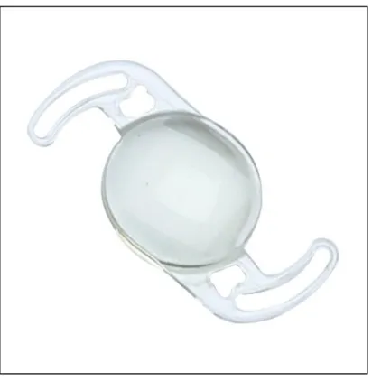
In this experiment, hydrophilic acrylic IOLs was used from Gennext aspheric Foldable IOL which is made from natural yellow material with a special monomer containing the identical chromophore present in the human crystalline lens. Natural Yellow is the first IOL material to incorporate the same UV-A blocking and violet light filtering chromophore that is in the human crystalline lens. The approach, to UV blockers and violet filters is to use nature’s own solutions to the problem of protecting the retina from harmful energetic light[42]. The figure of IOL is shown in Figure 3.7 and the specification of the lens are described in the following Table 3.1:
Figure 3.7: Hydrophilic acrylic IOL[43]
Table 3.1: Description of IOL
Lens Model YSQ FL600ASP
Optic Design Aspheric/Double Square Edge 1 Biconvex
Optic Diameter 6.0 mm
Overall Length 12.5 mm
HapticAngle 00 , Elastic band design
A-Constant 118.2
Diopter Range 8 to 30 (in 0.5 increment in D+ 18 to 25)
Water Content 25% BENZ
All lenses were extracted from the original packages and immersed in saline solution in the water bulb. According to the previous studies [12][13][44][16], glistening generation is processed between two temperature change within 48 hours. For this purpose, EC water bath model(EW-100K) is used in which the temperature setting is available from 0°C to 100C. Firstly, microvacuoles were induced by taking the IOL from its room temperature environment and placed it into an induction at temperature of 45°C for 24 hours. Then, another temperature is set with 35°C for 24 hours in the water tub. Afterward, the lenses were removed from the oven and measure at room temperature. The densities of induced microvacuoles vary with the time following their removal from the oven. For this reason, restrictions were made with respect to the time points of measurements. The following Figure 3.8 shows how to induce the IOL in the water tub.
Figure 3.8: Induction of IOL to generate microvacuoles
Chapter 4
Image Analysis for glistenings in IOL
IOL images are analyzed to obtain the number and size of glistenings for optical simulation in the next step by using the image processing technique. In the previous chapter, glis- tenings are generated in the laboratory and discussed at glistening generation in section 3.7. In this research, we employed an open-source library ImageJ[45] for image analysis.
Firstly, glistening is detected from microscopic images and analyze the particles according to the following Figure 4.1.
Figure 4.1: Flow chart of Image Analysis
4.1 Microscopic Images of IOL
To calculate light scattering in IOL from microscopic images, lens imaging is performed by confocal microscopy and dark field microscopy. Confocal microscopy has a limited depth of focus in which images were taken throughout the thickness of the lens and then stacked.
This kind of microscopy has a small field of view and thus, it is needed for three or more lateral displacements across the lens to capture the complete central optic body. Dark field microscopy is used as the intraocular lens is needed to be retro-illuminated with an annulus of light and thus, a large field of view is the main difference from confocal microscopy[16].
In order to capture glistenings inside the lens, an inverted microscope(Olympus IX73) is used for nano-sized particles or micro-sized particles in which the light source and the
”condenser” lens are above the specimen. Figure 4.2 shows the Olympus IX72, an inverted lens for capturing microscopic images. In fact, Olympus IX72 can provide UIS2 optical system and focus 10 mm. Moreover, the observation method is available for Fluorescence (Blue/Green Excitation), Fluorescence (Ultraviolet Excitation), Differential Interference Contrast (DIC), Phase Contrast, bright field. The observation tube is Widefield (FN 22) for tilting binocular and trinocular. The objective is on the bottom and thus, it can focus the light to produce a real image.
Figure 4.2: Lens imaging with microscope
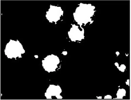
If there are no glistenings for light scatter, the image is black. Otherwise, glistenings can be seen as while particles in a dark background. Next, Image analysis methods are applied to identify the size and number of the microvacuoles from the images for light scatter calculation.
4.1.1 Glistening and Whitening in IOL images
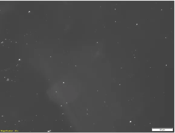
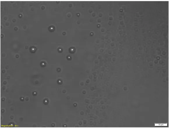
The lab-induced glistenings and whitening are taken by an inverted microscope and shows in Figures 4.3, 4.4, 4.5, and 4.6. IOL images are captured with different magnification to have better result such as 20X, 40X, and 60X.However, microscopic image with 40X magnification(Figure 4.5) is used for the glistening measurement in this experiment. Since
glistenings are very small in microscopic image of IOL, the image is divided into 25 images to be a high performance in image processing algorithm but size of images are the same.
Figure 4.3: Glistening in microscopic image of IOL with 20X magnification
Figure 4.4: Glistening in microscopic image of IOL with 20X magnification
Figure 4.5: Glistening in microscopic image of IOL with 40X magnification
Figure 4.6: Glistening in microscopic image of IOL with 60X magnification
4.2 Background Subtraction
Image preprocessing is performed to adjust images which is applicable for the next step of glistening computation process in IOL. Firstly, the input images are converted into gray- scale 8 bit images. From this gray-scale image, background subtraction is proceeded.
Background subtraction is important for an uneven background in the image. In IOL images, glistening are very small and other lighting condition can also have some impacts to distinguish background and foreground and thus, background subtraction is considered based on “rolling ball” algorithm [46]. The algorithm assumes 2D grayscale image has a height dimension defined by the intensity value at every point in the image, then a ball (filtering object) rolls over the image in order to find smooth continuous background.
When a ball with a radius sufficiently large not to fall into points moves on this surface, its center generates another surface, whose shape is affected by only general grayscale variations.
The center of the filtering object, a surface from the top of a sphere have a radius(R) which is moved along each scan line of the image. Therefore, the surface is tangent to the image at one or more points with every other point on the surface below the corresponding (x, y) point of the image. Any point either on or below the surface during this process is considered part of the background. The following equation shows that the background subtraction by the rolling ball method:
gbg(x, y) = (goriginal(x, y) + 1)–(C(x, y)–R) (4.1) where C(x, y) is the patch generated by the ball center and R is the ball radius. Figure 4.7 shows a schematic diagram of background subtraction by rolling ball method. In this diagram, the histogram indicates the surface determined by the original grayscale distribution goriginal(x, y); (1) surface C(x, y), generated by the ball center; (2) surface (C(x, y)–R), determined by the point of the ball contact with the surface goriginal(x, y;
(3) (goriginal(x, y) + 1); and (4) new grayscale distribution with the uniform background gbg(x, y) = (goriginal(x, y) + 1)–(C(x, y)–R).
Figure 4.7: Schematic diagram of background subtraction by rolling ball method [47]
Background subtraction with rolling ball algorithm is applied to glistening images in IOL and the result can be seen as Figure 4.8.
Figure 4.8: Background subtraction in microscopic image of IOL
4.3 Thersholding
Thresholding is the simplest method of image segmentation which can be used to cre- ate binary images from grayscale images[48]. Image segmentation means the process of partitioning a digital image into multiple segments (sets of pixels, also known as image objects). The goal of segmentation is to simplify and/or change the representation of an image into something that is more meaningful and easier to analyze [49][48]. Therefore, the outcome of the preprocessed image is feeding to the segmentation stage. Glistening features in IOL image are extracted from the surroundings using a thresholding technique in which all gray levels below the threshold are mapped into black, those levels above are mapped into white, or vice versa.[50]. In this research, the thresholding function is used based on the isodata algorithm [51] and applied in the glistening images.
gbinary(x, y) =T(gbg(x, y), t) (4.2) where gbg(x, y) is the subtracted background image and T is the thresholding function in which t is defined as threshold value. Therefore, t value is calculated from isodata thresholding. However, the output of Isodata thresholding for microscopic image is shown in Figure 4.9.
Figure 4.9: Thresholding in microscopic image of IOL
In fact, Isodata theresholding divides the image into objects and background by taking an initial threshold. Firstly, a threshold value t is defined from the range of gray values in the image. Then, the mean of all pixels with a gray value less then or equal to t is calculated as mL and the mean of all pixels with gray value greater than t are also calculated as mH. Afterward, the averages from two values are calculated but the threshold value is incremented and the process is repeated until the threshold is larger than the composite average. Thus, Isodata thresholding can be written as:
t = mL+mH
2 (4.3)
From the above equation, the value of t is between mL and mH and thus, both mL and mH are also functions of t. Therefore, the above equation can be transformed into:
t= mL(t)+mH(t)
2 =m(t) (4.4)
where function m is defined. A point t such that t = m(t) is called a fixed point of the function m. Starting from an initial estimate to the fixed point can be found with fixed point iteration:
ti+1 =m(ti) (4.5)
This process is repeated on the input image until the threshold version remains constant for further iterations.
4.4 Fill Holes
After thresholding of microscopic IOL images, we fill all the holes of every detected edge by filling the holes. In fact, the image contains foreground objects surrounded by back- ground regions. However, some imperfections in the binary image are set of background regions lying completely within the foreground regions due to imperfection in the binary
conversion identified by thresholding. Therefore, these holes are filled in glistenings of microscopic IOL images and shows as Figure 4.10.
I(x, y) =max(gbinary, O(C(O(gbinary)))) (4.6)
Figure 4.10: Filling holes in microscopic image of IOL
4.5 Separation of Overlapping objects
Watershed segmentation is applied to binary IOL images because some of the glisten- ing particles are closed and touched each other after filling holes. Watershed segmenta- tion algorithm based on mathematical morphology is a well known image segmentation approach[52][53]. This method is based on the approach of geography in which pixel values are in the altitude while other local minimum values and its surrounding regions represent basins. Firstly, the algorithm assumes that the work flow as filling water to the basin, and two or more basins water meet as dam. That is called watershed line in which the basins are located between the boundaries. This process will finish when all basins have surrounded the dam. After watershed segmentation has applied in IOL im- ages, glistenings segmentation and overlapping parts are separated and easier to identify for counting in the next step. Figure 4.11 shows how the watershed algorithm separates the touching glistening particles.
Figure 4.11: Overlapping parts are separated by watershed algorithm
4.6 Glistening counting
The main purpose of image analysis is to know the number and size of glistening for light scatter calculation from lab-induced glistenings. Therefore, all segmented images are automatically counted by image processing. In this step, we obtain the information of each glistening by outlining the numbers. Figure 4.12 shows how automatic glistening counting from the segmented image of IOL.
Figure 4.12: Glistening counting in microscopic image of IOL
4.7 Glistening measurements
The next result of automatic glistening counting is the size of glistenings. Since the area of glistening particles is computed, the diameter of each particles is calculated again by the following equations. However, we assume all the particles are spheres for light scattering calculation in the next chapter.
diameter= 2∗p
area/Π (4.7)
4.8 Result of Image Analysis
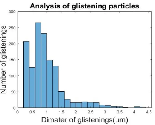
The result of induced microvacuoles from IOL is analyzed by image analysis. From this analysis, the size of glistening and the number of glistening can be achieved. The following Figure 4.13 shows the number and size of glistening from this experiment. Although size is one of the parameters to calculate T-matrix light scattering, the diameter or radius of spherical particles are taken in the algorithm. Hence, the diameter is converted from the size of glistening, and all glistening particles are assumed to be sphere.
Figure 4.13: number and diameter of glistening from IOL image analysis
4.8.1 Diameter of glistening
The goal of using image analysis tools to IOL images is to achieve the specific data of lab-produced microvacuoles. After 48 hours of consequent heating in two different temperatures, the maximum size of glistenings can be seen around 4µm and the minimum
![Figure 4.7: Schematic diagram of background subtraction by rolling ball method [47]](https://thumb-ap.123doks.com/thumbv2/123deta/6153295.1082125/38.918.282.607.770.1079/figure-schematic-diagram-background-subtraction-rolling-ball-method.webp)